EP0249152B1 - Enwicklungsanlage für elektrophotographisches Gerät - Google Patents
Enwicklungsanlage für elektrophotographisches Gerät Download PDFInfo
- Publication number
- EP0249152B1 EP0249152B1 EP87108086A EP87108086A EP0249152B1 EP 0249152 B1 EP0249152 B1 EP 0249152B1 EP 87108086 A EP87108086 A EP 87108086A EP 87108086 A EP87108086 A EP 87108086A EP 0249152 B1 EP0249152 B1 EP 0249152B1
- Authority
- EP
- European Patent Office
- Prior art keywords
- developer
- developing
- casing
- toner
- developing unit
- Prior art date
- Legal status (The legal status is an assumption and is not a legal conclusion. Google has not performed a legal analysis and makes no representation as to the accuracy of the status listed.)
- Expired - Lifetime
Links
Images


Classifications
-
- G—PHYSICS
- G03—PHOTOGRAPHY; CINEMATOGRAPHY; ANALOGOUS TECHNIQUES USING WAVES OTHER THAN OPTICAL WAVES; ELECTROGRAPHY; HOLOGRAPHY
- G03G—ELECTROGRAPHY; ELECTROPHOTOGRAPHY; MAGNETOGRAPHY
- G03G15/00—Apparatus for electrographic processes using a charge pattern
- G03G15/06—Apparatus for electrographic processes using a charge pattern for developing
-
- B—PERFORMING OPERATIONS; TRANSPORTING
- B82—NANOTECHNOLOGY
- B82Y—SPECIFIC USES OR APPLICATIONS OF NANOSTRUCTURES; MEASUREMENT OR ANALYSIS OF NANOSTRUCTURES; MANUFACTURE OR TREATMENT OF NANOSTRUCTURES
- B82Y15/00—Nanotechnology for interacting, sensing or actuating, e.g. quantum dots as markers in protein assays or molecular motors
-
- G—PHYSICS
- G03—PHOTOGRAPHY; CINEMATOGRAPHY; ANALOGOUS TECHNIQUES USING WAVES OTHER THAN OPTICAL WAVES; ELECTROGRAPHY; HOLOGRAPHY
- G03G—ELECTROGRAPHY; ELECTROPHOTOGRAPHY; MAGNETOGRAPHY
- G03G15/00—Apparatus for electrographic processes using a charge pattern
- G03G15/06—Apparatus for electrographic processes using a charge pattern for developing
- G03G15/08—Apparatus for electrographic processes using a charge pattern for developing using a solid developer, e.g. powder developer
- G03G15/0822—Arrangements for preparing, mixing, supplying or dispensing developer
- G03G15/0848—Arrangements for testing or measuring developer properties or quality, e.g. charge, size, flowability
- G03G15/0849—Detection or control means for the developer concentration
-
- G—PHYSICS
- G03—PHOTOGRAPHY; CINEMATOGRAPHY; ANALOGOUS TECHNIQUES USING WAVES OTHER THAN OPTICAL WAVES; ELECTROGRAPHY; HOLOGRAPHY
- G03G—ELECTROGRAPHY; ELECTROPHOTOGRAPHY; MAGNETOGRAPHY
- G03G15/00—Apparatus for electrographic processes using a charge pattern
- G03G15/06—Apparatus for electrographic processes using a charge pattern for developing
- G03G15/08—Apparatus for electrographic processes using a charge pattern for developing using a solid developer, e.g. powder developer
- G03G15/0822—Arrangements for preparing, mixing, supplying or dispensing developer
- G03G15/0848—Arrangements for testing or measuring developer properties or quality, e.g. charge, size, flowability
- G03G15/0849—Detection or control means for the developer concentration
- G03G15/0853—Detection or control means for the developer concentration the concentration being measured by magnetic means
-
- G—PHYSICS
- G03—PHOTOGRAPHY; CINEMATOGRAPHY; ANALOGOUS TECHNIQUES USING WAVES OTHER THAN OPTICAL WAVES; ELECTROGRAPHY; HOLOGRAPHY
- G03G—ELECTROGRAPHY; ELECTROPHOTOGRAPHY; MAGNETOGRAPHY
- G03G15/00—Apparatus for electrographic processes using a charge pattern
- G03G15/06—Apparatus for electrographic processes using a charge pattern for developing
- G03G15/08—Apparatus for electrographic processes using a charge pattern for developing using a solid developer, e.g. powder developer
- G03G15/0822—Arrangements for preparing, mixing, supplying or dispensing developer
- G03G15/0887—Arrangements for conveying and conditioning developer in the developing unit, e.g. agitating, removing impurities or humidity
- G03G15/0889—Arrangements for conveying and conditioning developer in the developing unit, e.g. agitating, removing impurities or humidity for agitation or stirring
Definitions
- the present invention relates to a developing unit for an electro-photographic apparatus, such as a copier or a printer. More specifically, the present invention relates to a toner concentration sensor for the developing unit.
- An electro-photographic apparatus generally includes a latent image forming drum coated with photosensitive material, a developing unit for developing the latent image into a visible image, and means for fixing the developed image onto paper.
- the developing unit generally includes: a casing for containing developer, which is a mixture of a carrier and toner; a paddle roller for paddling the developer; a developing roller for carrying the developer to the latent image forming drum, and a toner concentration sensor for sensing and controlling the toner concentration of the developer and maintaining adequate developing quality.
- the senor is provided on a blade which regulates the thickness of the layer of developer disposed on the developing roller.
- the sensor should sense the developer actually being supplied to the developing roller, i.e., as the developer is paddled up by the paddle roller and poured onto the developing roller.
- the developer scraped off by the blade must be of the same concentration as the developer actually used for the development of the latent image. Therefore, it is logical that measurement at the blade should accurately reflect the developing quality.
- the output signal of the sensor provided at the blade is insufficient for accurate control of the toner concentration. More particularly, the output of the sensor fluctuates according to fluctuation of flow of the developer at the blade.
- US-A-4 088 092 discloses the provision of a coil, for detecting toner density in developer, which is located at the bottom of a developer tank.
- the flow of developer, including the toner, in relation to which the coil works, is directed from an agitator towards a developing roller at which developer flow is restricted by a doctor blade. With this type of flow the accuracy of detection of toner density is not entirely satisfactory.
- EP-A-0 086 516 discloses an arrangement similar to that of US-A-4 088 092.
- An embodiment of this invention provides a developing unit with means for accurately sensing and controlling the toner concentration.
- An embodiment of this invention provides a developing unit with a toner concentration sensor which accurately outputs a signal without any fluctuation.
- a developing unit for developing a latent image formed on a photosensitive material comprising:
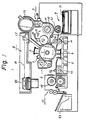
- Fig. 1 is a schematic side view of an electro-photographic apparatus embodying the present invention, in this instance a printer.
- a latent image forming drum 1 is shown which is coated on its outer surface with photosensitive material and rotated in the clockwise direction at a predetermined speed.
- the drum 1 is surrounded by a coronacharger 2, a developing unit 3, an image transferring discharger 4, a paper separating discharger 5, a cleaner 6, and a decharger 7.
- the photosensitive surface of the latent image forming drum 1 is uniformly charged by the charger 2, then scanned by a light beam 81 supplied by an optical system 8 for forming an electrostatic latent image.
- the optical system 8 includes a laser source (not illustrated), an optical shutter (not illustrated), a polygon mirror 82 for scanning, and a reflection mirror 83.
- the latent image is then developed by the toner supplied by the developing unit 3.
- a sheet of paper 91 is taken out from a paper cassette 9 by a pick roller 92, and fed to the drum 1 by a pair of feed rollers 10.
- the developed image i.e., a toner image
- the paper 91 bearing the toner image is separated from the drum 1 by the paper separating discharger 5, and fed to a fixing unit 11 through another pair of feed rollers 12.
- the fixing unit 11 has a heat roller 111 for thermally fixing the toner image on the paper 91.
- the paper 91 including the image is stacked on a stacker 13.
- the drum 1 is further rotated, cleaned by the cleaner 6, decharged by the decharger 7, and again uniformly charged by the charger 2 for the next latent image forming.
- the developing unit 3 includes: a casing 30 for containing the developer; a toner concentration sensor 31; a paddle roller 32; a developing roller 33; a regulating blade 34; a flow restricting plate 35; a toner hopper 36; a toner supply roller 37; and a toner concentration controller 38 which controls the rotation of the toner supply roller 37 in response to an output signal from the sensor 31.
- the tiny dots indicate the developer 40 which is a mixture of the carrier and the toner, as known in the art.
- the carrier consists of microscopic grains of magnetic material.
- the toner is a powder of carbon-based plastics.
- the developer 40 is paddled and mixed by the paddle roller 32 and, at the same time, scooped up and poured onto the developing roller 33.
- conventional magnets are provided at specific positions, so that the carrier of the developer 40 (together with the toner) is attracted to the surface of the developing roller 33 by the magnetic force.
- the extra developer 40 on the developing roller 33 is scraped off by the blade 34 and returns to the paddle roller 32 by flowing over the plate 35 as indicated by arrow R in FIG. 2.
- the developer 40 on the developing roller 33 which is made into a specific thickness, is then carried to the latent image forming drum 1 while the developing roller 33 is rotated. The above-mentioned magnets are not rotated.
- the toner touching the latent image forming drum 1 is transferred onto the drum 1 by an electrostatic force, while the carrier remains on the developing roller 33 surface by the magnetic force.
- the carrier on the developing roller comes to a place where there is no magnetic force, the carrier is released from the developing roller 33 and falls to the bottom of the casing 30 together with the remaining toner that was not used for development.
- the bunch of carrier grains accumulated on the developing roller 33 is usually called a "magnetic brush" for painting the drum 1 with the toner.
- a toner concentration sensor 31 ⁇ is positioned at the blade 34 as shown by a dotted line in FIG. 2. This position is chosen, as mentioned before, because of an intention to measure the concentration of the developer 40 actually supplied to the developing roller 33.
- the actual flow of the developer 40 fluctuates due to the fact that the developer 40 is supplied occasionally, rather than continuously, by each of the paddle fins 32a of the paddle roller 32. Namely, the amount of extra developer 40 scraped off by the blade 34 and returned to the paddle roller 32 flowing above the flow restricting plate 35 varies with time.
- the toner concentration sensor 31 ⁇ usually senses the magnetic reluctance, or its inverse value admittance, the sensor output represents not only the concentration, namely a proportion of the toner to the carrier, but also the variation in the quantity thereof.
- the embodiment of the present invention accomplishes a more accurate reading of toner concentration by providing the sensor 31 between the paddle roller 32 and the developing roller 33 and near the bottom 29 of the casing 30, as illustrated in FIG. 2.
- FIG. 3 shows a comparison of output signals from a plurality of sensors, each provided at a position A, B, C, D or E, respectively, as illustrated in FIG. 4.
- the vertical axis denotes an analog output level of the sensors which is proportional to the magnetic admittance of the developer 40.
- the horizontal axis denotes the actual toner concentration.
- the sensors are so adjusted that their outputs would be 2.5V at the concentration of 4%.
- the measured values at every position A-E exhibit some fluctuation more or less (see FIG. 3 and explanation below).
- the plotted values in FIG. 3 are averages of a certain period of time at each point.
- the curve A is not proportional to the concentration, perhaps because the absolute quantity of the developer 40 at position A is too small.
- the signals from A are much more amplified than the others.
- the curve B is very proportional to the toner concentration and its tilt is steep.
- the curves C and D are also proportional to the concentration, but their tilts are less steep.
- the curve E could be said to be proportional to the concentration, but not straightly proportional.
- FIG. 5 shows the fluctuations of the output signals from sensors at positions B to E.
- the vertical axis denotes the analog output level and the horizontal axis denotes time.
- the curve A is not illustrated for simplicity, because it is not proportional to the concentration and is useless.
- the vertical segments on the curves B and E indicate regions of fluctuations.
- For the curves C and D there is no indication of fluctuations; these outputs are less useful, however, since they increase as time passes. This dependence on time is a disadvantage for a quick start of the apparatus.
- the reason curves C and D depend on time is unknown.
- the curves B and E have peaks at the start.
- FIG. 6 also shows the fluctuations in a different way.
- the vertical axis denotes the output analog level and the horizontal axis denotes trial numbers. Namely, the measurement trial was carried out ten (10) times, and each time the measured values were plotted. Each trial includes two (2) minutes of continuous rotation of the rollers 32 and 33, and a five (5) minute recess. The plotted value is an average value of each two minute operation period. As apparent from this Figure, the output E fluctuates significantly on each trial, while the output B hardly fluctuates.
- FIG. 7 further shows a response characteristic of the sensors 31 to the toner consumption at the developing roller 33.
- the vertical axis denotes the output analog level and the horizontal axis denotes time, wherein a printing starts at the two minute time point, and the toner is supplied at the four minute time point.
- the thickness of the developer on the developing roller 33 is made greater than that of B and E, because the output signal is too small and too much fluctuating would occur if the thickness was the same.
- the output A is too sensitive to the instantaneous consumption of the toner, and is likely to cause a toner shortage signal even if enough toner is present at the paddle roller 32.
- the paddling roller 32 may be replaced by another type of device, such as a vibrating plate or a screw, etc.
- the toner supply roller 37 and the toner concentration controller 38 may be replaced by a manually operated supply mechanism and a toner shortage alarm indicator, to create a less expensive apparatus. Accordingly, all suitable modifications and equivalents may be resorted to, falling within the scope of the invention according to the appended claims.
Landscapes
- Physics & Mathematics (AREA)
- General Physics & Mathematics (AREA)
- Chemical & Material Sciences (AREA)
- Engineering & Computer Science (AREA)
- Nanotechnology (AREA)
- Health & Medical Sciences (AREA)
- Life Sciences & Earth Sciences (AREA)
- General Health & Medical Sciences (AREA)
- Molecular Biology (AREA)
- Crystallography & Structural Chemistry (AREA)
- Dry Development In Electrophotography (AREA)
- Magnetic Brush Developing In Electrophotography (AREA)
Claims (8)
- Entwicklereinheit zum Entwickeln eines latenten Bildes, welches auf einem lichtempfindlichen Material (1) gebildet wird, mit:(a) einem Gehäuse (30), zur Aufnahme von Entwickler (40), der aus einer Mischung von magnetischem Träger und nicht nichtmagnetischem Toner besteht;(b) einer Entwicklereinrichtung (33), die, durch Magnetkraft, Entwickler von dem Gehäuse (30) zu einem Entwicklungsbereich überträgt, der in einer Position neben dem lichtempfindlichen Material (1) vorgesehen ist, und überschüssigen Entwickler von dem Entwicklungsbereich zu dem Boden des Gehäuses (30) zurückführt, stromabwärts im Sinne der Übertragungsrichtung des Entwicklers;(c) einer Mischeinrichtung (32,32a) zum Mischen des Entwicklers, die neben dem Boden des Gehäuses (30) vorgesehen sind, welche Mischeinrichtung angeordnet ist, um sowohl Entwickler zwischen der Mischeinrichtung und dem Boden des Gehäuses (30) in einer Richtung von der Entwicklereinrichtung (33) fort längs der Oberfläche des Bodens des Gehäuses (30) zu übertragen, als auch um den übertragenen Entwickler an die Entwicklereinrichtung (33) zu liefern, wodurch ermöglicht wird, daß der Entwickler zwischen der Entwicklereinrichtung (33) und der genannten Mischeinrichtung (32,32a), und Entwickler zwischen der Entwicklereinrichtung (33) und dem Boden des Gehäuses (30), zwischen der Mischeinrichtung und dem Boden des Gehäuses fließt, und(d) einer Einrichtung (31) zum Fühlen des Verhältnisses von Toner relativ zum Träger in dem Entwickler, die betreibbar ist, um ein Signal auszugeben, welches jenes Verhältnis darstellt, vorgesehen am Boden des Gehäuses (30) zwischen der Entwicklereinrichtung (33) und der Mischeinrichtung (32,32a), so daß eine detektierende Oberfläche davon mit dem Entwickler in Kontakt plaziert ist, der zwischen der Mischeinrichtung und dem Boden des Gehäuses fließt.
- Entwicklereinheit nach Anspruch 1, bei der die genannte Mischeinrichtung (32,32a) eine Paddeleinrichtung zum Paddeln des Entwicklers (40) ist.
- Entwicklereinheit nach Anspruch 1 oder 2, ferner mit:(e) einer Einrichtung (37) zum Liefern von Toner in das Gehäuse; und(f) eine Einrichtung (38) zum Steuern der Tonerliefereinrichtung ansprechend auf das Signal, welches von der Tonerfühleinrichtung (31) ausgegeben wird.
- Entwicklereinheit nach Anspruch 2, oder Anspruch 3 in Verbindung mit Anspruch 2, bei der die Paddeleinrichtung eine rotierende Paddelrolle (32) ist, die eine Vielzahl von Paddelblättern (32a) an ihrem Umfang hat.
- Entwicklereinheit nach einem der vorhergehenden Ansprüche, bei der die Entwicklereinrichtung (33) eine Entwicklerrolle ist, die magnetische Einrichtungen enthält, um eine magnetische Kraft an ihren ausgewählten Umfangsabschnitten zu erzeugen, um selektiv den Träger und den Toner anzuziehen und freizugeben.
- Entwicklereinheit nach einem der vorhergehenden Ansprüche, bei der die Tonerfühleinrichtung (31) einen magnetischen Zugang des Entwicklers fühlt.
- Entwicklereinheit nach einem der vorhergehenden Ansprüche, ferner mit:
einer Einrichtung (34) zum Regulieren der Dicke einer Schicht des Entwicklers, der auf der Entwicklerrolle (33) angezogen worden ist. - Entwicklereinheit nach Anspruch 7, bei der die Regulierungseinrichtung ein Blatt (34) ist, welches neben der Oberfläche der Entwicklerrolle (33) vorgesehen ist.
Applications Claiming Priority (2)
| Application Number | Priority Date | Filing Date | Title |
|---|---|---|---|
| JP136192/86 | 1986-06-13 | ||
| JP61136192A JPS62293267A (ja) | 1986-06-13 | 1986-06-13 | 現像装置 |
Publications (2)
| Publication Number | Publication Date |
|---|---|
| EP0249152A1 EP0249152A1 (de) | 1987-12-16 |
| EP0249152B1 true EP0249152B1 (de) | 1992-01-15 |
Family
ID=15169493
Family Applications (1)
| Application Number | Title | Priority Date | Filing Date |
|---|---|---|---|
| EP87108086A Expired - Lifetime EP0249152B1 (de) | 1986-06-13 | 1987-06-04 | Enwicklungsanlage für elektrophotographisches Gerät |
Country Status (6)
| Country | Link |
|---|---|
| US (1) | US4739365A (de) |
| EP (1) | EP0249152B1 (de) |
| JP (1) | JPS62293267A (de) |
| KR (1) | KR910002443B1 (de) |
| CA (1) | CA1279088C (de) |
| DE (1) | DE3775996D1 (de) |
Families Citing this family (12)
| Publication number | Priority date | Publication date | Assignee | Title |
|---|---|---|---|---|
| US5009187A (en) * | 1987-08-25 | 1991-04-23 | Sharp Kabushiki Kaisha | Developing device with shutter |
| JPH0239076A (ja) * | 1988-07-28 | 1990-02-08 | Fujitsu Ltd | 現像剤の濃度検出装置 |
| US5049938A (en) * | 1989-04-11 | 1991-09-17 | Minolta Camera Kabushiki Kaisha | Abnormality detecting system in an image forming apparatus |
| JPH0323479A (ja) * | 1989-06-20 | 1991-01-31 | Fujitsu Ltd | 現像器のトナー検出方法 |
| JP2974334B2 (ja) * | 1989-08-31 | 1999-11-10 | キヤノン株式会社 | 現像装置 |
| US5005516A (en) * | 1989-12-01 | 1991-04-09 | Eastman Kodak Company | Device for aiding in measuring pigmented marking particle level in a magnetic brush development apparatus |
| DE69111123T2 (de) * | 1990-04-18 | 1995-11-09 | Matsushita Electric Ind Co Ltd | Entwicklungsgerät. |
| CA2063920C (en) * | 1991-03-29 | 1999-03-30 | Masato Ishii | Toner quantity detecting system for an image recording apparatus, a method of detecting the quantity of toner and a developing device for the image recording apparatus |
| US5428427A (en) * | 1992-12-14 | 1995-06-27 | Samsung Electronics Co., Ltd. | Device for detecting toner used in an electrophotography machine |
| US5893007A (en) * | 1996-12-24 | 1999-04-06 | Samsung Electronics Co., Ltd. | Combination development unit and toner level detection service |
| JP4617094B2 (ja) * | 2004-03-31 | 2011-01-19 | キヤノン株式会社 | 画像形成装置 |
| JP5982829B2 (ja) * | 2011-11-30 | 2016-08-31 | 株式会社リコー | 現像装置、及びプロセスユニット、及び画像形成装置 |
Family Cites Families (9)
| Publication number | Priority date | Publication date | Assignee | Title |
|---|---|---|---|---|
| JPS52131729A (en) * | 1976-04-28 | 1977-11-04 | Ricoh Co Ltd | Toner concentration detection circuit |
| JPS5349437A (en) * | 1976-10-16 | 1978-05-04 | Hitachi Ltd | Toner density detector |
| JPS57172235A (en) * | 1981-04-16 | 1982-10-23 | Olympus Optical Co Ltd | Detector for toner density |
| JPS57202569A (en) * | 1981-06-08 | 1982-12-11 | Minolta Camera Co Ltd | Electrophotographic copier |
| EP0086516B1 (de) * | 1982-02-11 | 1986-05-28 | Agfa-Gevaert N.V. | Xerografisches Kopiergerät |
| JPS58159551U (ja) * | 1982-04-20 | 1983-10-24 | オリンパス光学工業株式会社 | トナ−濃度検知装置 |
| EP0127916B1 (de) * | 1983-06-03 | 1987-10-28 | Agfa-Gevaert N.V. | Steuerung der Tonerpulververteilung |
| US4536080A (en) * | 1983-08-19 | 1985-08-20 | Xerox Corporation | Developer material end of life sensing |
| JPS6076774A (ja) * | 1983-10-04 | 1985-05-01 | Fuji Xerox Co Ltd | 現像剤濃度検出装置 |
-
1986
- 1986-06-13 JP JP61136192A patent/JPS62293267A/ja active Pending
-
1987
- 1987-05-28 US US07/055,038 patent/US4739365A/en not_active Expired - Lifetime
- 1987-06-04 DE DE8787108086T patent/DE3775996D1/de not_active Expired - Lifetime
- 1987-06-04 EP EP87108086A patent/EP0249152B1/de not_active Expired - Lifetime
- 1987-06-04 KR KR1019870005656A patent/KR910002443B1/ko not_active Expired
- 1987-06-12 CA CA000539574A patent/CA1279088C/en not_active Expired - Lifetime
Also Published As
| Publication number | Publication date |
|---|---|
| KR910002443B1 (ko) | 1991-04-22 |
| DE3775996D1 (de) | 1992-02-27 |
| JPS62293267A (ja) | 1987-12-19 |
| KR890000935A (ko) | 1989-03-17 |
| US4739365A (en) | 1988-04-19 |
| CA1279088C (en) | 1991-01-15 |
| EP0249152A1 (de) | 1987-12-16 |
Similar Documents
| Publication | Publication Date | Title |
|---|---|---|
| US4734737A (en) | Control of toner concentration in a developer | |
| US5272503A (en) | Replaceable sub-assemblies for electrostatographic reproducing machines | |
| US7860415B2 (en) | Image forming apparatus with toner concentration sensor | |
| US4506804A (en) | Volume detecting device | |
| EP0506423B1 (de) | Tonermengen-Nachweissystem für ein Bildaufzeichnungsgerät, Verfahren zum Nachweis der Tonermenge und eine Entwicklungsvorrichtung für ein Bildaufzeichnungsgerät | |
| US5802419A (en) | Image forming apparatus and process cartridge for image forming apparatus | |
| US4739365A (en) | Developing unit for an electro-photographic apparatus | |
| US5450177A (en) | Image forming apparatus having a toner concentration control capability with a toner concentration sensor disposed in a developing unit | |
| EP0532308B1 (de) | Auswechselbare Einzelteile für elektrostatografische Kopiermaschinen | |
| EP0863446B1 (de) | Nachweis für Toneraufbrauch in einem adaptiven elektrophotographischen Drucksystem | |
| CA1290007C (en) | Electrophotographic recording method and apparatus | |
| EP0542502B1 (de) | Verfahren und System zur Steuerung der Tonerzuführung | |
| US5212522A (en) | Basic developability control in single component development system | |
| US5909604A (en) | Image forming apparatus having developer collection container | |
| JPH0519933B2 (de) | ||
| JPH09304979A (ja) | 画像形成装置 | |
| JP3602940B2 (ja) | トナー濃度制御方法および装置 | |
| JPH0619334A (ja) | 画像形成装置 | |
| JP3316659B2 (ja) | 電子写真装置 | |
| JPH09301551A (ja) | 画像形成装置 | |
| JPH03161782A (ja) | 画像形成装置 | |
| JP2801198B2 (ja) | 画像濃度制御方法 | |
| JP3041708B2 (ja) | 画像形成装置 | |
| JP2893858B2 (ja) | 現像剤濃度測定装置 | |
| JPH0233170A (ja) | トナー濃度制御方法 |
Legal Events
| Date | Code | Title | Description |
|---|---|---|---|
| PUAI | Public reference made under article 153(3) epc to a published international application that has entered the european phase |
Free format text: ORIGINAL CODE: 0009012 |
|
| AK | Designated contracting states |
Kind code of ref document: A1 Designated state(s): DE FR GB IT |
|
| 17P | Request for examination filed |
Effective date: 19880601 |
|
| 17Q | First examination report despatched |
Effective date: 19910313 |
|
| GRAA | (expected) grant |
Free format text: ORIGINAL CODE: 0009210 |
|
| AK | Designated contracting states |
Kind code of ref document: B1 Designated state(s): DE FR GB IT |
|
| REF | Corresponds to: |
Ref document number: 3775996 Country of ref document: DE Date of ref document: 19920227 |
|
| ET | Fr: translation filed | ||
| ITF | It: translation for a ep patent filed | ||
| PLBE | No opposition filed within time limit |
Free format text: ORIGINAL CODE: 0009261 |
|
| STAA | Information on the status of an ep patent application or granted ep patent |
Free format text: STATUS: NO OPPOSITION FILED WITHIN TIME LIMIT |
|
| 26N | No opposition filed | ||
| REG | Reference to a national code |
Ref country code: GB Ref legal event code: IF02 |
|
| PGFP | Annual fee paid to national office [announced via postgrant information from national office to epo] |
Ref country code: GB Payment date: 20050601 Year of fee payment: 19 |
|
| PGFP | Annual fee paid to national office [announced via postgrant information from national office to epo] |
Ref country code: DE Payment date: 20050602 Year of fee payment: 19 |
|
| PGFP | Annual fee paid to national office [announced via postgrant information from national office to epo] |
Ref country code: FR Payment date: 20050608 Year of fee payment: 19 |
|
| PG25 | Lapsed in a contracting state [announced via postgrant information from national office to epo] |
Ref country code: GB Free format text: LAPSE BECAUSE OF NON-PAYMENT OF DUE FEES Effective date: 20060604 |
|
| PGFP | Annual fee paid to national office [announced via postgrant information from national office to epo] |
Ref country code: IT Payment date: 20060630 Year of fee payment: 20 |
|
| PG25 | Lapsed in a contracting state [announced via postgrant information from national office to epo] |
Ref country code: DE Free format text: LAPSE BECAUSE OF NON-PAYMENT OF DUE FEES Effective date: 20070103 |
|
| GBPC | Gb: european patent ceased through non-payment of renewal fee |
Effective date: 20060604 |
|
| REG | Reference to a national code |
Ref country code: FR Ref legal event code: ST Effective date: 20070228 |
|
| PG25 | Lapsed in a contracting state [announced via postgrant information from national office to epo] |
Ref country code: FR Free format text: LAPSE BECAUSE OF NON-PAYMENT OF DUE FEES Effective date: 20060630 |