EP0249023A1 - Séparateur à chambre de tourbillonnement - Google Patents
Séparateur à chambre de tourbillonnement Download PDFInfo
- Publication number
- EP0249023A1 EP0249023A1 EP87106289A EP87106289A EP0249023A1 EP 0249023 A1 EP0249023 A1 EP 0249023A1 EP 87106289 A EP87106289 A EP 87106289A EP 87106289 A EP87106289 A EP 87106289A EP 0249023 A1 EP0249023 A1 EP 0249023A1
- Authority
- EP
- European Patent Office
- Prior art keywords
- flow
- vortex
- vortex chamber
- swirl
- chamber separator
- Prior art date
- Legal status (The legal status is an assumption and is not a legal conclusion. Google has not performed a legal analysis and makes no representation as to the accuracy of the status listed.)
- Granted
Links
- 239000007789 gas Substances 0.000 claims abstract description 52
- 238000000926 separation method Methods 0.000 claims abstract description 45
- 238000000034 method Methods 0.000 claims abstract description 14
- 239000007788 liquid Substances 0.000 claims abstract description 12
- 239000002245 particle Substances 0.000 claims abstract description 12
- 239000007787 solid Substances 0.000 claims abstract description 7
- 238000007654 immersion Methods 0.000 claims description 52
- 239000000428 dust Substances 0.000 claims description 16
- 230000004087 circulation Effects 0.000 claims description 8
- 230000015572 biosynthetic process Effects 0.000 claims description 6
- 238000009826 distribution Methods 0.000 claims description 5
- 230000003247 decreasing effect Effects 0.000 claims description 4
- 239000011324 bead Substances 0.000 claims description 2
- 230000003111 delayed effect Effects 0.000 claims description 2
- 241001237823 Paenibacillus vortex Species 0.000 claims 1
- 230000008569 process Effects 0.000 abstract description 2
- 230000009467 reduction Effects 0.000 description 11
- 230000008901 benefit Effects 0.000 description 7
- 230000007423 decrease Effects 0.000 description 6
- 230000000694 effects Effects 0.000 description 6
- 238000010276 construction Methods 0.000 description 5
- 230000006872 improvement Effects 0.000 description 3
- 230000001133 acceleration Effects 0.000 description 2
- 238000006073 displacement reaction Methods 0.000 description 2
- 230000000977 initiatory effect Effects 0.000 description 2
- 239000002184 metal Substances 0.000 description 2
- 230000002093 peripheral effect Effects 0.000 description 2
- 238000004140 cleaning Methods 0.000 description 1
- 230000008878 coupling Effects 0.000 description 1
- 238000010168 coupling process Methods 0.000 description 1
- 238000005859 coupling reaction Methods 0.000 description 1
- 125000004122 cyclic group Chemical group 0.000 description 1
- 230000001419 dependent effect Effects 0.000 description 1
- 238000011038 discontinuous diafiltration by volume reduction Methods 0.000 description 1
- 239000006185 dispersion Substances 0.000 description 1
- 239000012717 electrostatic precipitator Substances 0.000 description 1
- 239000004744 fabric Substances 0.000 description 1
- 230000009969 flowable effect Effects 0.000 description 1
- 239000012530 fluid Substances 0.000 description 1
- 238000004519 manufacturing process Methods 0.000 description 1
- 239000000203 mixture Substances 0.000 description 1
- 238000012856 packing Methods 0.000 description 1
- 238000011084 recovery Methods 0.000 description 1
- 230000007704 transition Effects 0.000 description 1
Images


Classifications
-
- B—PERFORMING OPERATIONS; TRANSPORTING
- B01—PHYSICAL OR CHEMICAL PROCESSES OR APPARATUS IN GENERAL
- B01D—SEPARATION
- B01D17/00—Separation of liquids, not provided for elsewhere, e.g. by thermal diffusion
- B01D17/02—Separation of non-miscible liquids
- B01D17/0217—Separation of non-miscible liquids by centrifugal force
-
- B—PERFORMING OPERATIONS; TRANSPORTING
- B01—PHYSICAL OR CHEMICAL PROCESSES OR APPARATUS IN GENERAL
- B01D—SEPARATION
- B01D21/00—Separation of suspended solid particles from liquids by sedimentation
- B01D21/0087—Settling tanks provided with means for ensuring a special flow pattern, e.g. even inflow or outflow
-
- B—PERFORMING OPERATIONS; TRANSPORTING
- B01—PHYSICAL OR CHEMICAL PROCESSES OR APPARATUS IN GENERAL
- B01D—SEPARATION
- B01D21/00—Separation of suspended solid particles from liquids by sedimentation
- B01D21/26—Separation of sediment aided by centrifugal force or centripetal force
- B01D21/265—Separation of sediment aided by centrifugal force or centripetal force by using a vortex inducer or vortex guide, e.g. coil
-
- B—PERFORMING OPERATIONS; TRANSPORTING
- B01—PHYSICAL OR CHEMICAL PROCESSES OR APPARATUS IN GENERAL
- B01D—SEPARATION
- B01D45/00—Separating dispersed particles from gases or vapours by gravity, inertia, or centrifugal forces
- B01D45/12—Separating dispersed particles from gases or vapours by gravity, inertia, or centrifugal forces by centrifugal forces
- B01D45/16—Separating dispersed particles from gases or vapours by gravity, inertia, or centrifugal forces by centrifugal forces generated by the winding course of the gas stream, the centrifugal forces being generated solely or partly by mechanical means, e.g. fixed swirl vanes
-
- B—PERFORMING OPERATIONS; TRANSPORTING
- B04—CENTRIFUGAL APPARATUS OR MACHINES FOR CARRYING-OUT PHYSICAL OR CHEMICAL PROCESSES
- B04C—APPARATUS USING FREE VORTEX FLOW, e.g. CYCLONES
- B04C3/00—Apparatus in which the axial direction of the vortex flow following a screw-thread type line remains unchanged ; Devices in which one of the two discharge ducts returns centrally through the vortex chamber, a reverse-flow vortex being prevented by bulkheads in the central discharge duct
- B04C3/06—Construction of inlets or outlets to the vortex chamber
-
- B—PERFORMING OPERATIONS; TRANSPORTING
- B04—CENTRIFUGAL APPARATUS OR MACHINES FOR CARRYING-OUT PHYSICAL OR CHEMICAL PROCESSES
- B04C—APPARATUS USING FREE VORTEX FLOW, e.g. CYCLONES
- B04C5/00—Apparatus in which the axial direction of the vortex is reversed
- B04C5/12—Construction of the overflow ducting, e.g. diffusing or spiral exits
- B04C5/13—Construction of the overflow ducting, e.g. diffusing or spiral exits formed as a vortex finder and extending into the vortex chamber; Discharge from vortex finder otherwise than at the top of the cyclone; Devices for controlling the overflow
-
- B—PERFORMING OPERATIONS; TRANSPORTING
- B04—CENTRIFUGAL APPARATUS OR MACHINES FOR CARRYING-OUT PHYSICAL OR CHEMICAL PROCESSES
- B04C—APPARATUS USING FREE VORTEX FLOW, e.g. CYCLONES
- B04C5/00—Apparatus in which the axial direction of the vortex is reversed
- B04C5/24—Multiple arrangement thereof
-
- B—PERFORMING OPERATIONS; TRANSPORTING
- B04—CENTRIFUGAL APPARATUS OR MACHINES FOR CARRYING-OUT PHYSICAL OR CHEMICAL PROCESSES
- B04C—APPARATUS USING FREE VORTEX FLOW, e.g. CYCLONES
- B04C7/00—Apparatus not provided for in group B04C1/00, B04C3/00, or B04C5/00; Multiple arrangements not provided for in one of the groups B04C1/00, B04C3/00, or B04C5/00; Combinations of apparatus covered by two or more of the groups B04C1/00, B04C3/00, or B04C5/00
Definitions
- the invention relates to a method for separating and / or separation of solid and / or liquid particles (disperse phase) from gaseous and / or liquid media (continuous phase) as well as for separating mixed gases (G as-gas separation) and / or mixed liquids (liquid-liquid separation) as well as for sifting and / or classifying with a swirl chamber separator, in which a centrifugal force field is generated, from which the specifically lighter fraction is created by two immersion pipes protruding coaxially and in mirror image to the median planes within the central area of the Vortex chamber separator is sucked off, and the formation of vortex chamber separators for performing the method, with at least one vortex chamber with a sharp trailing edge and two immersion tubes, which are arranged coaxially in the vortex chamber, each extend from the end walls of each other and with a clean gas outlet in connection stand and with one em widening spout are provided, with a guide device possibly being provided between the inner inlet ends.
- the vortex separation process as a fluid mechanical separation process, in which centrifugal forces are used to separate or separate a heavier disperse phase from a lighter, continuous, flowable carrier phase from aero-dispersions and / or hydrodispersions, is known per se.
- DE-A1 32 03 498 e.g. a generic. Vortex chamber separator described.
- this has the disadvantage that, due to flow losses in the swirl chamber separator, its separating capacity is relatively low in relation to the energy input and the multi-chamber arrangements which are often required to increase the separating capacity have a relatively large construction volume. This limits the area of use of the known swirl chamber separators.
- the object of the invention is to improve the known vortex chamber separator in such a way that when the flow losses are reduced, the separation performance of the vortex chambers is improved, and in the case of multi-chamber arrangements with increased separation performance, a reduction in the construction volume is achieved.
- the object is achieved in that the contact zone between the main flow and the vortex is set so as to limit the cylinder losses so that the tangential entry pulse into the bottom layer flow is increased by reducing the proportion of the bottom layer flow that circulates in the vortex chamber is that in order to reduce the impulse mixing losses due to dissipative pressure loss in the flow in the main channel, the bottom layer flow is formed rotationally symmetrically with constant or approximately constant mean main flow velocity, so that the clean gas flow is guided through the immersion tubes with cross sections widening towards the outlet in such a way that in zones of highest flow velocity the The flow is only burdened with weak meridian flow deflections and that the clean gas flow on the outer wall of the immersion tubes increases with G to the inlet sections speed is performed.
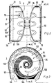
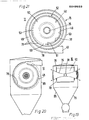
- F ig. 1 shows, in a broken perspective view, a swirl chamber separator 1 in which the raw gas volume flow 88 is introduced into the separator housing 52 through a raw gas inlet 87.
- the raw gas volume is divided in the swirl chamber separator 1 in a known manner into a clean gas volume flow 96 and a residual raw gas volume flow 97.
- the residual raw gas volume flow 97 exits the separator housing 52 through the residual raw gas outlet 95.
- the clean gas volume flow 96 is led out of the separator housing 52 through two immersion tubes 35 in the region of the upper swirl chamber bottom 92 and the lower swirl chamber bottom 91.
- the immersion tubes 35 have a cross section widening from the inlet section 36 to the outlet section 37 and are designed like a trumpet.
- a secondary flow 89 forms on the main flow channel bend 90.
- a secondary flow 104 is present in each case on the swirl chamber bottoms 91, 92.
- Another spatial transverse secondary flow is indicated by reference number 101.
- a further secondary flow 120 flows as a meridian component on the outer wall of the immersion tubes 35.
- a vortex 54 is formed transversely to the central axis of the dip tubes 35, which is shown in FIG. 2.
- a wall layer flow 99 consisting of meridian components is formed in the area of the main flow channel bend 90.
- the coarse separation zone 98 is located on the main flow channel bend 90, the solids separated out here being discharged through discharge gaps 78 formed in the swirl chamber bottoms 91, 92.
- a fine separation zone 100 is formed at the transition from the vortex chamber bottoms 90, 91 to the immersion tubes 35.
- immersion tubes 35 Compared to cylindrical immersion tubes, immersion tubes 35, like the trumpet-type immersion tubes 35 shown in FIG. 1, are distinguished by various advantages.
- the gentler flow guidance during the deflection of the meridian flow leads to lower radial angular momentum losses and to an improvement in the separation performance of the vortex chamber 50 in comparison to vortex chambers with cylindrical immersion tubes.
- the dip tubes 35 are formed with a progressively increasing wall curvature in the axial planes from the inlet section to the outlet section, the local angular momentum losses are further reduced, the flow being additionally loaded only with weak meridian flow deflections in the zones of highest flow velocities.
- the dip tubes 35 with a variable cross-section reduce the volumetric area of the dissipative vortex flow field.
- the wall flow therefore only has to drive a smaller vortex volume. This reduces dissipative pressure loss components in the flow. The result of this is that the output angular momentum, which develops from an essentially straight flow with an almost tangential peripheral entry into the circulating flow, has more impulse components for acceleration the wall flow are released. This results in a further improvement in the separation performance of the vortex chamber 50.
- the volume reduction in the vortex flow field leads to shorter particle transport routes for the particles P separated in the fine separation zone 100 in axial planes through the field of the vortex 54. This enables these particles P to be removed more quickly from the vortex chamber 50, which simplifies the separation process.
- the radial secondary flow 104 on the swirl chamber bottoms 91, 92 also has a concentrating effect because of the small inward displacement forces. This arises from the fact that the particles P are moved on the main flow channel bend 90 of the main flow channel 69 at approximately the continuum speed present there and thereby flow into the zone of the bottom sink flow at a higher speed than they are moved there themselves.
- the increase in the local angular momentum losses in the bottom sink flow in cylindrical dip tubes is reduced in the dip tubes 35 by the increase in the dip tube diameter in the region of the vortex chamber bottoms 91, 92.
- the reason for this is the radial reduction of the plane angular momentum transport zone in the area of the swirl chamber bottoms 91, 92, with a simultaneous restriction to outer radius areas with weaker cross-sectional reduction influences. As a result, the concentration disadvantageous for the angular momentum is reduced.
- the surfaces of the vortex chamber bottoms 91, 92 also form zones which are ineffective for the secondary flow, since in them the displacement forces for the particles P are radial and rectified with the meridian flow.
- the reduction of the separation effective floor areas by the immersion tubes 35 with a variable cross section thus increases the separation efficiency of the swirl chamber 50. At the same time an increase in the highly separating fine separation zone 100 is achieved by the immersion tubes 35.
- the separation effect begins at the level end of the meridian flow where the wall profile curvature the dip tubes 35 uses.
- Cross-flow separation prevails in the fine separation zone 100, which sets in very quickly and then intensifies considerably as the immersion tube diameter decreases depending on the location.
- the greater the extension of the fine separation zone by the immersion tubes 35 of variable cross section the more and the faster particles P can be separated from the meridian flow in the course of the helical flow path.
- a reduction in the particle concentration in the clean gas volume flow 96 is achieved.
- the local loss of angular momentum in this area of the flow field is reduced by the faster local concentration reduction. This enables local higher speeds of rotation, which in turn accelerates the reduction in concentration.
- immersion tubes 35 with a variable cross-section results in cyclically supporting fluidic and separation mechanical improvements in the fine separation zone, which are characterized by higher separation and separation performance of the swirl chamber 50 with less pressure loss compared to the use of cylindrical immersion tubes.
- the immersion tubes 35 can have a progressively increasing wall curvature from the inlet section 36 to the outlet section 37 in the coaxial plane.
- the arrangement of the contact zone 93 between the main flow in the main flow channel 69 and the vortex 54 is of particular importance.
- the position of the contact zone 109 influences the rotational strength of the vortex field and thus the increase in the separation and separation efficiency of the vortex chamber 50.
- the larger main flow deflections caused by this result in lower flow losses when introducing angular momentum.
- the angular momentum initiation Losses arise from the mixture of the impulse components I k and Im.
- I k is the impulse component of the bottom layer flow, which enters the swirl chamber 50 as a driving angular momentum from the high-energy main flow.
- Im is a secondary momentum of the bottom layer flow circulating within the vortex chamber 50. Both impulse components penetrate the bottom layer flow in spirally narrowing zones with continuous impulse strength compensation by mixing. A large relative contact arc length therefore causes an increase in the I k zones and a reduction in the Im zones, as a result of which greater rotational speeds are achieved on the immersion tube 35 (FIG. 3).
- a rotational symmetry of the flow on the contact arc 109 should be aimed for.
- the local flow cross sections of the main flow channel 69 decrease uniformly in the main flow direction in such a way that a constant or at least approximately constant mean main flow rate is obtained in the main flow channel 69. This then causes constant or approximately constant circumferential speeds at the periphery of the vortex 54 in the region of the contact zone 109.
- rotationally symmetrical or largely rotationally symmetrical circumferential and radial speed distributions are achieved in the bottom layer flow.
- FIG. 4 shows the spiral curvatures of the main flow channel arch 90 and the vortex-maple arch 106 in comparison to the reference circle 108 of the main flow channel arch and the reference circle 105 of the swirl chamber 50.
- the main flow is cut from the leading edge 103 by the spiral curvature of the cylinder jacket 48.
- part of the high-energy main flow is fed to the vortex 54 over the entire length of the leading edge 103, which thereby also receives a driving rotary flow impulse on the vortex chamber jacket.
- the spiral curvatures of the cylinder jacket 90 of the main flow channel 69 and of the cylinder jacket 48 of the vortex chamber 50 can produce an extensive hotation symmetry of the entire vortex chamber rotational flow, which starts from the vortex rotation axis, which corresponds to the central axis 58 of the vortex.
- the separation efficiency is increased, since the enhanced corner flow speeds are increased by the increased secondary flow.
- the swirl chamber 50 can also be designed such that the main flow channel arch 90 is circular and only the swirl chamber arch 106 is spirally curved. As a result, swirl chambers 50 with shorter contact arc lengths of the contact zone 109 are possible, which can offer advantages in the design of series connections of swirl chambers 50 and in production.
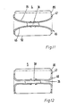
- the immersion tubes 35 While in the vortex chamber 50 in the fine separation zone 100 on the outer wall of the dip tubes 35 high rotational speeds of the flow are aimed for, the high kinetic flow energy must be converted back into pressure within the dip tubes.
- the immersion tubes 35 as already explained for the swirl chamber separator 1, are designed with a cross section widening from the inlet section 36 to the outlet section 37, so that a swirl diffuser is created for the internal flow of the immersion tubes 35.
- a trumpet-like configuration of the swirl diffuser in axial section with a wall curvature which is initially weak and then increasingly stronger in the flow direction has proven to be particularly advantageous.
- other designs of the dip tubes 35 are also possible. It is particularly advantageous to convert the inner tube flow into an annular flow through an inner tube core or diffuser body 38.
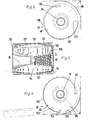
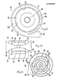
- a swirl chamber separator 2 is shown, in which a spiral housing 39 is arranged as a swirl diffuser at the outlet section 37 of each immersion tube 35.
- the diffuser inner body 38 opens tangentially into this spiral housing 39. Outlet gaps 78 are formed on the housing bottom 86 of the separator housing 52.
- the vortex chamber separator 2 thus represents a directly separating vortex separator.
- the inner diffuser bodies 38 are formed in one piece by means of a guide body 41.
- the guide body 41 has a radially extending bead 42, by means of which flow guide surfaces 43 assigned to the dip tubes 35 are formed.
- the dip tube openings 107 are lip-shaped.
- the spiral housing 44 has a cross section widening in the flow direction and is thus optimized as a swirl diffuser.
- the spiral housing 44 can, as shown in FIG. 10, have one flow outlet or else several tangential flow outlets.
- the trumpet-like curvature of the annular gap swirl diffuser 46 ends in an axial section in a plane perpendicular to the central axis of the immersion tube 35 in order to make the radial expansion of the local annular gap cross sections as large as possible.
- the spiral housing 44 following the annular gap swirl diffuser 46 can be of relatively simple design.
- the swirl chamber separator 4 has two dip tubes 35, which are designed as a trumpet-shaped annular gap swirl diffusers 46 by means of a diffuser inner body 38. These end at the housing bottoms 86 of the separator housing 52, so that a smaller size compared to the swirl chamber separator 3 is achieved.
- Deflection vanes 47 are arranged in the outlet area 45 of the annular-gap swirl diffuser 46 and serve to untwist the inner tube flow, which is delayed circumferentially and meridially up to the outlet area (FIG. 11).
- the deflection blades 47 can be curved sheet metal blades and / or can be profiled.
- FIG. 12 shows a swirl chamber separator 5 which is simplified compared to the swirl chamber separator 4, in which a section of the immersion tube 35 with the associated diffuser inner body 38 is cylindrical and only widens on the housing base 86.
- the annular gap swirl diffuser 46 also has deflection vanes 47 on the housing base 86 (FIG. 12).
- FIGS. 13 to 16 further vortex chamber separators 6, 7, 8, 9 are shown schematically, which differ with regard to the design of the immersion tubes 35.
- the immersion tubes 35 are arranged in structurally simplified vortex chambers 50 without discharge gaps with sharp flow corners.
- the outlet sections 37 of the immersion tubes 35 extend beyond the housing bottoms 86 of the swirl chambers 50.
- the immersion tubes 35 themselves are designed in a simplified trumpet-like manner, with the swirl chamber separator 7 also having a trumpet-like inner diffuser body 38, through which an annular-gap swirl diffuser 46 is formed in the immersion tubes 35.
- the diffuser inner body 38 Due to the special design of the diffuser inner body 38, local harmful backflows are suppressed with secondary or tertiary circulation, such as occur in the dip tube without a core and interfere with the layer flow delay. It is possible to provide an end spiral housing or end guide vanes in the annular gap swirl diffuser 46 on the outside.
- the swirl chamber separator 8 according to FIG. 15 is particularly suitable due to its simplified design as an element for simple series connections or parallel connections of swirl chambers 50. Since the outlet sections 37 of the trumpet-shaped immersion tubes 35 end in the plane of the housing bottoms 86, an extremely compact separator housing 52 results (FIG. 15).
- FIG. 16 A further simplified embodiment of a swirl chamber separator 9 is shown in FIG. 16.
- 52 immersion tubes 35 are arranged in a square separator housing and are designed as conical swirl diffusers.
- the end sections 37 of the immersion tubes 35 protrude beyond the housing base 86.
- conical diffuser inner bodies 35 in the conical immersion tubes, which are not shown in more detail.
- End guide vanes or an end spiral housing can also be provided at the outlet section 37 of the immersion tubes 35, while the swirl chamber 50 itself can be provided with discharge gaps.
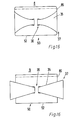
- the vertical secondary velocities on both sides of the trailing edge 66 are directed in the same direction and are locally the same size. 17 and 18, this is achieved in that the wall supplied to the trailing edge 66 from the main flow channel 69 also has a concave cylindrical shape. In this case, the trailing edge 66 flows into two concave curved wall layer flows both from the vortex 54 and from the main flow channel 69.
- the cylinder jacket 48 of the swirl chamber 50 can be spirally curved, such as, for. B. be logarithmically spirally curved (Fig. 20). This will make the middle one E inlingersströmungs technically about kept constant in the outer wall layer flow as a peripheral speed, or even increased in the circumferential direction of the flow path, provided that the radial distances of the shell wall layer flow decrease from the vortex axis of rotation. The influence of the braking of the wall friction is compensated for by the spiral guidance of the jacket wall layer flow with a decreasing radius of curvature.
- a pre-separator channel 49 is provided in front of the main gas flow inlet opening of the main flow channel 69 and has the same overall height as the separator housing 52.
- the pre-separator channel 49 is rectangular in cross section. Discharge gaps 78 can be provided at all corner flow zones of the pre-separator channel 49 which are concave for the main flow and which reinforce the pre-separation.
- the rectangular flow cross sections in the pre-separator channel 49 can either be kept constant or can continuously narrow in accordance with the spiral turns in the main flow direction. This would accelerate the pre-separator flow until it enters the swirl chamber 50, which is equipped with a spiral cylinder jacket 48, so that the separation efficiency increases.
- FIG. 22 and 23 show a swirl chamber separator 12 designed as a spiral direct separator 76, in which the raw gas enters the swirl chamber 50 via the raw gas inlet 87 is fed via a plurality of tangential entry gaps 56.
- the vortex 54 is distanced from the main flow channel 69 by flow guide lamellae 57.
- the individual binocular gaps 56 are each arranged between two flow guide fins 57, which together form an arbiter housing 55.
- the inlet gaps 56 are arranged parallel to the vortex axis, have the same gap widths and extend over the entire height of the vortex chamber 50. The separation and separation capacities increase with the number of inlet gaps 56.
- the flow guide fins 57 are expediently of the same design.
- the main flow channel 69 can, as shown in FIG. 22, be designed such that a circulating distributor flow is formed. However, it is possible to arrange the number of gaps and the flow guide fins 57 such that the distributor flow ends in an inlet gap 56 after one revolution or less.
- both in the vortex and in the ver divider housing can be formed in the flat housing bases discharge gaps 78 in order to utilize as much as possible the separation effect of the secondary layer flows which are strongly curved in these corners.
- the spiral direct separator 76 according to FIG. 23 is connected to a dust bunker 80 via the discharge column 78.
- FIG. 24 shows a vortex chamber separator 13 in which a plurality of circular guide vane rings 59 are arranged in the radial direction of the central axis 58 of the vortex 54 surrounding it. These have different reference radii and consist of uniformly distributed curved flow guide plates 57. An inlet gap 56 is formed in each case between the individual flow guide plates 57. At all concave flow corners including the outer spiral-cylindrical housing casing, discharge gaps 78 can be arranged in the flat housing bases, so that an increased dust discharge effect is achieved in the distribution housing 55.
- the flow guide lamellae 57 in the swirl chamber separator 13 can be designed as sheet metal blades or guide plates, since the influence of the thickness of a profiling would have only a slight influence on the flow.
- the flow guide fins 57 are curved spirally or logarithmically.
- the setting on each guide vane ring 59 to form a rotationally symmetrical spiral primary flow takes place in accordance with the respective local reference radii.
- the spiral curvatures aimed for the flow guide fins 57 can also be approximated here by circular arcs.
- FIG. 25 shows a swirl chamber separator 14 which has three swirl chambers 50 which are arranged in a common separator housing 52.
- the main flow Channel 69 is guided around the swirl chambers 50, the opening cross section of the main flow channel 69 being reduced in sections after each swirl chamber 50 for reasons of continuity in the flow direction.
- curved baffles 61 or baffle profiles 62 are arranged, optionally with a thickness distribution.
- the guide plates 61 or guide profiles 62 are spirally or logarithmically spirally curved, but can also be designed in the shape of a circular arc and arranged spirally.
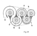
- the swirl chamber separator 15 shown in FIG. 26 as a compact arrangement of four swirl chambers 50 likewise has a circulating main gas stream 60.
- 14 guide profiles 62 are arranged as in the swirl chamber separator. These are designed such that the surface of the corresponding guide profile 62 facing the respective vertebra 54 is spirally curved and the convex outer surface 63 of the guide profile 62 is curved in a circular arc.
- the lugs 64 of the guide profiles 62 are shaped in such a way that for each swirl chamber 50 with the guide surface 65 to the trailing edge 66, an inflow section 67 with a cross section that decreases in the flow direction is formed.
- the compact arrangement of the vortex chamber separators 14 and 15 can be varied insofar as the last vortex chamber 50 in the flow direction can be designed as a direct separator with a flow inlet. In this case, since there is no residual raw gas outlet, there is no circulating distributor flow.
- the swirl chamber separators 14, 15 it is possible to optimize the swirl chamber separators 14, 15 in terms of their separating capacities and the desired reduction in pressure loss for the respective application.
- the vortex chambers 50 can also be connected directly to one another in different geometries as a series connection. Z are advantageous.
- These direct separating swirl chamber rows have the advantages of low and constant or largely constant individual ring gas dust contents and constant or largely constant solid raw gas dust contents of the individual swirl chambers. The individual residual raw gas dust content in the main flow direction can be reduced by appropriate design.
- the vortex chamber separator 16 which is designed as a series connection 68 of vortex chambers 50, offers a particular advantage of structural simplification without disturbing the flow of the vortex chambers (FIG. 27).
- the vortex chambers 50 are the same and aligned so that their central axes are aligned with each other on the same plane.
- the main flow channel 69 is distanced from the respective vortex chamber by a guide profile 62 with a contact arc angle of approximately 180 °.
- the free flow section of the main flow channel 69 is continuously reduced after each swirl chamber 50.
- the guide profiles 62 are spirally curved on the concave side and curved in a circular arc on the convex side. Since the cross section of the main flow channel 69 decreases in the direction of flow, the swirl chamber row is wedge-shaped, which offers advantages which can be used in construction.
- the vortex chamber 17 of Fig. 28 is composed of three R eihenscigenen 68, two of which are arranged parallel to each other, while the third opposite from is directed.
- the main flow channel 69 opens into two series connections 68, which open together into a return channel 111.
- the third series circuit whose output is connected to the main flow channel 69, is acted upon by the latter.
- the swirl chamber separator 17 can also be varied such that only two or three series circuits 68 connected in parallel are connected on the output side to a further series arrangement.
- Discharge gaps 78 can also be provided in the swirl chamber separator 17.
- the further elementary row shown in FIG. 29 can also be formed from the series circuit 68 with directly separating vortex chambers 50.
- the respective contact arc angle is designed as large as possible.
- the vortex chambers 50 then lie in a tight packing on a loop-shaped main flow channel 69.
- the lost construction volumes are relatively small in this embodiment.
- guide profiles 62 can also be used.
- the series circuit 70 as a compact swirl chamber separator 18.
- 30 shows a further embodiment of a swirl chamber separator 19 which consists of three swirl chambers 50 of decreasing diameter connected in series.
- Such a series connection 71a of vortex chambers 50 can be used in various ways to form apparatuses or systems with elementary rows arranged in parallel in circular sectors in circular sectors.
- an outer annular main flow channel 69 and a central swirl chamber 50 which can be designed as an end separator 74, cyclically arranged radially in series 71 of two swirl chambers 50.
- the main flow channel 69 can end at a series connection 71 or can be designed such that a circulating distributor flow is created.
- Discharge gaps 78 can be provided on the concave flow corner zones of the main flow channel 69, likewise in the swirl chambers 50. It is particularly advantageous that with cyclical parallel connections of the swirl chamber element rows, a streamlined and space-saving coupling possibility with a single end separator is provided, which, for. B. can be a spiral direct separator 76. With regard to its main flow channel 69, this is designed such that multiple angular momentum initiation is possible.
- the vortex chamber separator 20 is distinguished by a particularly compact design and can be produced from standardized components with only a small amount of lost construction volume.
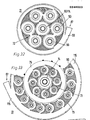
- a swirl chamber separator 21 it is also possible to design a swirl chamber separator 21 in such a way that a number of series connections 72 of the same swirl chambers 50 are cyclically peripherally connected in parallel (FIG. 32). On the output side, the series circuits 72 are connected to a swirl chamber 50 as a final separator .74. This end separator can also be designed as a spiral direct separator 76. The main flow channel 69 is guided in a circle around the arrangement of the series connections 72, so that a circulating flow is achieved.
- the vortex chamber rows 72 can consist of directly separating vortex chambers 50.
- the vortex chamber separator 22 according to FIG. 33 consists of two vortex chamber ring stages 73 which are arranged concentrically to one another and which are surrounded on the outside by the distribution channel 115.
- the outer swirl chamber ring stage 73 has swirl chambers 50 arranged parallel to one another, which are connected on the inside to an intermediate distributor channel 75. over the vortex chambers 50 of the inner vortex chamber ring stage 73 are connected to the end separator 74.
- This vortex chamber separator 22 is extraordinarily flexible in adapting to the respective purposes due to the large number of possible interconnections of vortex separators with vortex chambers 50. It is therefore not necessary to completely cover each vortex chamber ring stage 73 with vortex chambers 50. Rather, 50 dummy pieces or dummy ring elements can be used instead of individual swirl chambers, which are not shown in detail. It is therefore possible to create 22 cyclic modular systems with standard parts according to the principle of the vortex chamber separator.
- vortex chamber separators 16 and 23 to 30 are shown, which consist of different circuits of vortex chambers 50.
- the vortex chamber separators 23, 24, 16 are symbolized as elementary rows of vortex chambers 50, the incoming raw gas volume flow 88 and the emerging residual raw gas 97 being represented by arrows.
- FIG. 36 the continuity-related wedge-shaped convergence of the elementary row boundaries is shown using the example of the vortex chamber separator 16.
- group switching of different types can be carried out, which lead to vortex chamber separators corresponding to the type indicated in FIGS. 37 to 42.
- the grouping ratios depend on the total suction ratio of the respective elementary row of open simple or direct separating vortex chambers 50.
- the group circuits enable the advantage that standardized elementary rows of vortex chambers 50 can be used for the system design.
- Fig. 39 it is possible to use different grouping ratios of vertebral chamber element series within a plant or a multi-vertebral chamber system.
- the element series connections which decrease in stages are ultimately connected to an end separator, which can be a spiral direct separator 76 or else another direct separator.
- an end separator which can be a spiral direct separator 76 or else another direct separator.
- a fabric or electrostatic precipitator as the final separator, which can be made relatively small due to the preceding cleaning process.
- the residual volume flow of the last stage in the case of directly separating swirl chamber element rows can also be returned to the total raw gas inlet.
- the return volume flow can also be introduced between two stages of vortex chamber element series to be selected. Both circulation circuits and partial circulation circuits are thus possible.
- FIG. 43 shows, as a swirl chamber separator 31, a closed, direct separating swirl chamber elementary row with an inlet-cable main flow channel 69, three swirl chambers 50 and an end separator 74 designed as a spiral direct separator 76.
- This swirl chamber separator 31 can also be provided with guide plates 61 or guide profiles 62 in the area of the swirl chambers 50.
- Each swirl chamber elementary row 119 consists of a series connection 68, 71, 71a of swirl chambers 50, which is designed such that its housing 116 tapers in a wedge shape towards the exit end section for reasons of continuity.
- the individual rows of vortex chamber elements are connected to the total raw gas inlet channel 83 parallel to one another in such a way that the spaces 118 between the individual rows of vortex chamber elements 119 likewise widen in a wedge shape toward their end sections 117.
- the free space achieved in this way supports the function of the bunker suction device 81, which is formed on the dust bunker 80.
- the dust bunker 80 is formed by a housing 79, on the lower portion of which funnels 110 are arranged. The dust accumulating in the housing 79 can be removed via these funnels.
- the bunker suction device 81 is located on one side wall of the housing 79 seen. By means of this, a smaller volume flow is sucked out of the dust bunker 80 in order to generate a discharge flow in the discharge gaps 78 of the directly separating vortex chamber element rows, which are not shown in any more detail. This improves the dust discharge from the respective vortex chambers 50 and thus their separation performance.
- the wedge-shaped convergence of the housing boundaries of the elementary rows enables wedge-shaped gaps between the individual swirl chamber separators 31, as a result of which the gap discharge flow initiated by the bunker suction is evened out.
- a bunker suction device 81 is provided on the housing 79 of the dust bunker 80, the flow outlet 82 of which is connected to the total raw gas inlet channel 83 in the region of the raw gas inlet 87.
- An impact separator 85 is provided in front of the suction opening 84 of the bunker suction device 81. This plate-shaped impact separator 85 reduces the dust content of the volume flow to be extracted from the dust bunker 80 by the bunker suction device 81. The separating effect of the impact separator 85 is achieved by the strongly curved flow deflection at the plate edges.
- a direct separation system corresponding to the dedusting system 32, 33 can be provided, in which the swirl diffusers of the immersion tubes 35 located outside the separator housing 52 end in easy-to-create outer suction collection housings for the clean gas volume flow 96.
- a bunker suction device 81 is provided, the suction opening 84 of which is covered by an impact separator 85.
- This impact separator 85 is designed as a shielding plate in such a way that the bunker suction volume flow must be redirected to exit the dust bunker 80.
- a small rod separator 114 is provided, which serves to dedust the bunker suction volume flow.
- the small rod separator 114 can be a spiral direct separator 76.
Landscapes
- Chemical & Material Sciences (AREA)
- Chemical Kinetics & Catalysis (AREA)
- Physics & Mathematics (AREA)
- Thermal Sciences (AREA)
- Cyclones (AREA)
Priority Applications (2)
| Application Number | Priority Date | Filing Date | Title |
|---|---|---|---|
| AT87106289T ATE96687T1 (de) | 1986-05-09 | 1987-04-30 | Wirbelkammerabscheider. |
| EP91120013A EP0475467B1 (fr) | 1986-05-09 | 1987-04-30 | Séparateur à chambre de tourbillonnement |
Applications Claiming Priority (2)
| Application Number | Priority Date | Filing Date | Title |
|---|---|---|---|
| DE19863615747 DE3615747A1 (de) | 1986-05-09 | 1986-05-09 | Verfahren zum trennen und/oder abscheiden von festen und/oder fluessigen partikeln mit einem wirbelkammerabscheider mit tauchrohr und wirbelkammerabscheider zur durchfuehrung des verfahrens |
| DE3615747 | 1986-05-09 |
Related Child Applications (1)
| Application Number | Title | Priority Date | Filing Date |
|---|---|---|---|
| EP91120013.7 Division-Into | 1991-11-23 |
Publications (2)
| Publication Number | Publication Date |
|---|---|
| EP0249023A1 true EP0249023A1 (fr) | 1987-12-16 |
| EP0249023B1 EP0249023B1 (fr) | 1993-11-03 |
Family
ID=6300534
Family Applications (2)
| Application Number | Title | Priority Date | Filing Date |
|---|---|---|---|
| EP91120013A Expired - Lifetime EP0475467B1 (fr) | 1986-05-09 | 1987-04-30 | Séparateur à chambre de tourbillonnement |
| EP87106289A Expired - Lifetime EP0249023B1 (fr) | 1986-05-09 | 1987-04-30 | Séparateur à chambre de tourbillonnement |
Family Applications Before (1)
| Application Number | Title | Priority Date | Filing Date |
|---|---|---|---|
| EP91120013A Expired - Lifetime EP0475467B1 (fr) | 1986-05-09 | 1987-04-30 | Séparateur à chambre de tourbillonnement |
Country Status (5)
| Country | Link |
|---|---|
| US (3) | US4801310A (fr) |
| EP (2) | EP0475467B1 (fr) |
| JP (1) | JPS62289252A (fr) |
| AT (2) | ATE140162T1 (fr) |
| DE (3) | DE3615747A1 (fr) |
Cited By (4)
| Publication number | Priority date | Publication date | Assignee | Title |
|---|---|---|---|---|
| WO1991014494A1 (fr) * | 1990-03-23 | 1991-10-03 | Sundström Safety Ab | Separateur a cyclone |
| WO1991015301A1 (fr) * | 1990-03-30 | 1991-10-17 | Bielefeldt Ernst August | Separateur a chambre de turbulence |
| CN102008872A (zh) * | 2010-10-27 | 2011-04-13 | 常熟理工学院 | 扇形螺旋叶片 |
| CN102784726A (zh) * | 2012-07-18 | 2012-11-21 | 樊荣 | 一种旋风式气水分离器 |
Families Citing this family (92)
| Publication number | Priority date | Publication date | Assignee | Title |
|---|---|---|---|---|
| AT392425B (de) * | 1989-08-23 | 1991-03-25 | Voest Alpine Krems | Verfahren zum abtrennen von wenigstens einem stoff aus einem fluessigen oder gasfoermigen medium |
| FI902329A0 (fi) * | 1989-05-18 | 1990-05-09 | Voest Alpine Krems | Avskiljningsfoerfarande och -anordning. |
| AT391426B (de) * | 1989-05-18 | 1990-10-10 | Voest Alpine Krems | Verfahren und vorrichtung zum abtrennen von stoffen aus einem stroemenden medium |
| US5236587A (en) * | 1989-05-18 | 1993-08-17 | Josef Keuschnigg | Process and apparatus for the separation of materials from a medium |
| US5033915A (en) * | 1989-10-27 | 1991-07-23 | The Babcock & Wilcox Company | Low pressure drop steam/water conical cyclone separator |
| US5078880A (en) * | 1990-09-12 | 1992-01-07 | Water Technology Assessment Group | Vortex desalination system |
| US5393502A (en) * | 1993-09-07 | 1995-02-28 | International Purification Systems, Inc. | Solubilizing apparatus |
| US5553591A (en) * | 1994-06-20 | 1996-09-10 | Rockwell International Corp. | Engine power enhancement/pollution control system utilizing vortex air separator |
| US5517978A (en) * | 1994-06-20 | 1996-05-21 | Rockwell International Corporation | Pollution control system for an internal combustion engine |
| DE29501148U1 (de) * | 1995-01-25 | 1995-07-20 | Bielefeldt, Ernst-August, 24582 Bordesholm | Einrichtung zur Stofftrennung mittels Fliehkraft |
| DE19502202A1 (de) * | 1995-01-25 | 1996-08-22 | Ernst August Bielefeldt | Verfahren und Einrichtung zur Stofftrennung mittels Fliehkraft |
| US6277278B1 (en) * | 1998-08-19 | 2001-08-21 | G.B.D. Corp. | Cyclone separator having a variable longitudinal profile |
| US6312594B1 (en) * | 1998-08-19 | 2001-11-06 | G.B.D. Corp. | Insert for a cyclone separator |
| US6129775A (en) * | 1998-08-19 | 2000-10-10 | G.B.D. Corp. | Terminal insert for a cyclone separator |
| US6168716B1 (en) * | 1998-08-19 | 2001-01-02 | G.B.D. Corp. | Cyclone separator having a variable transverse profile |
| US7244396B2 (en) * | 1999-04-06 | 2007-07-17 | Uab Research Foundation | Method for preparation of microarrays for screening of crystal growth conditions |
| US6565321B1 (en) | 1999-05-21 | 2003-05-20 | Vortex Holding Company | Vortex attractor |
| US6595753B1 (en) | 1999-05-21 | 2003-07-22 | A. Vortex Holding Company | Vortex attractor |
| US6428589B1 (en) | 2000-09-29 | 2002-08-06 | Royal Appliance Mfg. Co. | Two-stage particle separator for vacuum cleaners |
| US6645382B1 (en) | 2000-11-13 | 2003-11-11 | George E. Wilson | Energy-efficient head cell entry duct |
| KR100438284B1 (ko) * | 2001-05-02 | 2004-07-02 | 병 도 김 | 볼텍스 튜브 이론을 이용한 배기가스 정화장치 |
| AU2003240105A1 (en) * | 2002-06-18 | 2003-12-31 | Awazel Waterproofing Company | Extraction methods and apparatus |
| CA2400258C (fr) | 2002-09-19 | 2005-01-11 | Suncor Energy Inc. | Separateur de mousse bitumineuse a plaques inclinees et methode de traitement d'hydrocarbures a l'aide d'un cyclone separateur |
| US7736501B2 (en) | 2002-09-19 | 2010-06-15 | Suncor Energy Inc. | System and process for concentrating hydrocarbons in a bitumen feed |
| US6935513B2 (en) * | 2002-12-18 | 2005-08-30 | Molecular Separation Technologies, Llc | Method and apparatus for mixture separation |
| US7048783B2 (en) * | 2004-04-13 | 2006-05-23 | Oreck Holdings, Llc | Vacuum cleaner air/liquid separator |
| RU2287359C2 (ru) * | 2004-11-30 | 2006-11-20 | Открытое акционерное общество "Минерально-химическая компания "ЕвроХим"(ОАО "МХК "ЕвроХим") | Вихревой аппарат для проведения физико-химических процессов с нисходящим потоком фаз |
| CA2652906C (fr) * | 2006-05-22 | 2015-07-14 | Contech Stormwater Solutions Inc. | Dispositif de separation de particules a partir d'eaux de pluie |
| US7842113B2 (en) * | 2006-09-20 | 2010-11-30 | Babcock & Wilcox Power Generation Group, Inc. | Extended water level range steam/water conical cyclone separator |
| US8735337B2 (en) * | 2007-03-13 | 2014-05-27 | Food Safety Technology, Llc | Aqueous ozone solution for ozone cleaning system |
| US9068149B2 (en) * | 2007-03-14 | 2015-06-30 | Food Safety Technology, Llc | Ozone cleaning system |
| US7637699B2 (en) * | 2007-07-05 | 2009-12-29 | Babcock & Wilcox Power Generation Group, Inc. | Steam/water conical cyclone separator |
| US9174845B2 (en) | 2008-07-24 | 2015-11-03 | Food Safety Technology, Llc | Ozonated liquid dispensing unit |
| US9522348B2 (en) | 2008-07-24 | 2016-12-20 | Food Safety Technology, Llc | Ozonated liquid dispensing unit |
| CN102224108B (zh) | 2008-12-01 | 2012-12-26 | 威立雅水务解决方案与技术支持公司 | 污水除砂方法和设备 |
| US7887613B2 (en) * | 2009-02-10 | 2011-02-15 | Panasonic Corporation Of North America | Vacuum cleaner having dirt collection vessel with toroidal cyclone |
| NL2002691C2 (en) * | 2009-03-31 | 2010-10-04 | Romico Hold A V V | Method for separating a medium mixture into fractions. |
| EP2449359B1 (fr) * | 2009-07-02 | 2020-01-01 | The Governors of the University of Alberta | Classificateur de particules |
| US8235128B2 (en) * | 2009-08-18 | 2012-08-07 | Halliburton Energy Services, Inc. | Flow path control based on fluid characteristics to thereby variably resist flow in a subterranean well |
| US9109423B2 (en) | 2009-08-18 | 2015-08-18 | Halliburton Energy Services, Inc. | Apparatus for autonomous downhole fluid selection with pathway dependent resistance system |
| US8276669B2 (en) * | 2010-06-02 | 2012-10-02 | Halliburton Energy Services, Inc. | Variable flow resistance system with circulation inducing structure therein to variably resist flow in a subterranean well |
| US8893804B2 (en) * | 2009-08-18 | 2014-11-25 | Halliburton Energy Services, Inc. | Alternating flow resistance increases and decreases for propagating pressure pulses in a subterranean well |
| CA2689021C (fr) | 2009-12-23 | 2015-03-03 | Thomas Charles Hann | Appareil et procede de regulation de debit par le truchement d'une caisse aspirante |
| US8708050B2 (en) | 2010-04-29 | 2014-04-29 | Halliburton Energy Services, Inc. | Method and apparatus for controlling fluid flow using movable flow diverter assembly |
| US8261839B2 (en) * | 2010-06-02 | 2012-09-11 | Halliburton Energy Services, Inc. | Variable flow resistance system for use in a subterranean well |
| AU2015201733B2 (en) * | 2010-06-02 | 2016-10-20 | Halliburton Energy Services, Inc. | Variable flow resistance with circulation inducing structure therein to variably resist flow in a subterranean well |
| US8356668B2 (en) * | 2010-08-27 | 2013-01-22 | Halliburton Energy Services, Inc. | Variable flow restrictor for use in a subterranean well |
| US8430130B2 (en) | 2010-09-10 | 2013-04-30 | Halliburton Energy Services, Inc. | Series configured variable flow restrictors for use in a subterranean well |
| US8950502B2 (en) | 2010-09-10 | 2015-02-10 | Halliburton Energy Services, Inc. | Series configured variable flow restrictors for use in a subterranean well |
| US8851180B2 (en) | 2010-09-14 | 2014-10-07 | Halliburton Energy Services, Inc. | Self-releasing plug for use in a subterranean well |
| US8387662B2 (en) | 2010-12-02 | 2013-03-05 | Halliburton Energy Services, Inc. | Device for directing the flow of a fluid using a pressure switch |
| US8602106B2 (en) | 2010-12-13 | 2013-12-10 | Halliburton Energy Services, Inc. | Downhole fluid flow control system and method having direction dependent flow resistance |
| US8555975B2 (en) | 2010-12-21 | 2013-10-15 | Halliburton Energy Services, Inc. | Exit assembly with a fluid director for inducing and impeding rotational flow of a fluid |
| EP2694776B1 (fr) | 2011-04-08 | 2018-06-13 | Halliburton Energy Services, Inc. | Procédé et appareil pour la régulation d'un écoulement de fluide dans une soupape autonome à l'aide d'un commutateur adhésif |
| US8678035B2 (en) | 2011-04-11 | 2014-03-25 | Halliburton Energy Services, Inc. | Selectively variable flow restrictor for use in a subterranean well |
| US8985150B2 (en) | 2011-05-03 | 2015-03-24 | Halliburton Energy Services, Inc. | Device for directing the flow of a fluid using a centrifugal switch |
| US9212522B2 (en) * | 2011-05-18 | 2015-12-15 | Thru Tubing Solutions, Inc. | Vortex controlled variable flow resistance device and related tools and methods |
| US8453745B2 (en) * | 2011-05-18 | 2013-06-04 | Thru Tubing Solutions, Inc. | Vortex controlled variable flow resistance device and related tools and methods |
| US8714262B2 (en) | 2011-07-12 | 2014-05-06 | Halliburton Energy Services, Inc | Methods of limiting or reducing the amount of oil in a sea using a fluid director |
| US8584762B2 (en) | 2011-08-25 | 2013-11-19 | Halliburton Energy Services, Inc. | Downhole fluid flow control system having a fluidic module with a bridge network and method for use of same |
| BR112014010371B1 (pt) | 2011-10-31 | 2020-12-15 | Halliburton Energy Services, Inc. | Aparelho para controlar o fluxo de fluido de forma autônoma em um poço subterrâneo e método para controlar o fluxo do fluido em um poço subterrâneo |
| BR112014008537A2 (pt) | 2011-10-31 | 2017-04-18 | Halliburton Energy Services Inc | aparelho para controlar de maneira autônoma o escoamento de fluido em um poço subterrâneo, e, método para controlar escoamento de fluido em um poço subterrâneo |
| US8739880B2 (en) | 2011-11-07 | 2014-06-03 | Halliburton Energy Services, P.C. | Fluid discrimination for use with a subterranean well |
| US9506320B2 (en) | 2011-11-07 | 2016-11-29 | Halliburton Energy Services, Inc. | Variable flow resistance for use with a subterranean well |
| US8684094B2 (en) | 2011-11-14 | 2014-04-01 | Halliburton Energy Services, Inc. | Preventing flow of undesired fluid through a variable flow resistance system in a well |
| EP2748469B1 (fr) | 2011-11-22 | 2019-12-25 | Halliburton Energy Services, Inc. | Ensemble de sortie ayant un organe de détournement de fluide qui déplace le chemin d'un fluide vers deux chemins ou plus |
| RU2014127437A (ru) * | 2011-12-16 | 2016-02-10 | Халлибертон Энерджи Сервисез, Инк. | Управление потоком текучей среды |
| EP2795178B1 (fr) * | 2011-12-21 | 2017-03-01 | Halliburton Energy Services, Inc. | Dispositif influençant l'écoulement |
| MY167298A (en) * | 2012-01-27 | 2018-08-16 | Halliburton Energy Services Inc | Series configured variable flow restrictors for use in a subterranean well |
| AT512151B1 (de) | 2012-05-24 | 2013-06-15 | A Tec Holding Gmbh | Vorrichtung zum Abtrennen von Stoffen aus einem Medium |
| US9404349B2 (en) | 2012-10-22 | 2016-08-02 | Halliburton Energy Services, Inc. | Autonomous fluid control system having a fluid diode |
| US9127526B2 (en) | 2012-12-03 | 2015-09-08 | Halliburton Energy Services, Inc. | Fast pressure protection system and method |
| US9695654B2 (en) | 2012-12-03 | 2017-07-04 | Halliburton Energy Services, Inc. | Wellhead flowback control system and method |
| US9370783B2 (en) * | 2014-03-28 | 2016-06-21 | Uop Llc | Apparatuses and methods for gas-solid separations using cyclones |
| CN104929575A (zh) * | 2015-05-26 | 2015-09-23 | 西南石油大学 | 相控阀 |
| EP3117904B1 (fr) * | 2015-07-17 | 2020-08-19 | MCI Management Center Innsbruck - Internationale Hochschule GmbH | Dispositif de separation pour de petites parties d'un flux de fluide |
| US9316065B1 (en) | 2015-08-11 | 2016-04-19 | Thru Tubing Solutions, Inc. | Vortex controlled variable flow resistance device and related tools and methods |
| AU2016314375A1 (en) | 2015-09-03 | 2018-04-26 | Aqua Hd Separation & Filtration Systems Ltd | A duct for use in a system for separating particles suspended in a fluid, and a method of designing such duct |
| SG11201806317SA (en) | 2016-01-25 | 2018-08-30 | Hydrocon Gmbh | Separator for separating solid matter from a fluid |
| US10569198B2 (en) * | 2016-07-19 | 2020-02-25 | Eaton Intelligent Power Limited | Fluid separator |
| IL251036A0 (en) | 2017-03-08 | 2017-06-29 | Aqua Hd Separation And Filtration Systems Ltd | System and method for separating particles suspended in a liquid |
| US10583382B2 (en) * | 2017-10-04 | 2020-03-10 | Bendix Commercial Vehicle Systems Llc | Effluent processing apparatus for a vehicle air brake charging system |
| KR101863026B1 (ko) * | 2018-01-04 | 2018-05-30 | 주식회사 포스코휴먼스 | 다중 사이클론을 이용한 집진 장치 |
| EP3539638B1 (fr) * | 2018-03-14 | 2021-02-24 | Tata Consultancy Services Limited | Appareil intégré de mélange et de séparation de phases de fluide et procédé associé |
| CN113056322A (zh) * | 2018-06-01 | 2021-06-29 | 莫比安尔私人公司 | 使用不需要过滤介质的低能多流分流器技术来清洁负载颗粒的流体的设备和方法 |
| CN113347911A (zh) * | 2019-01-25 | 2021-09-03 | 尚科宁家运营有限公司 | 用于真空清洁器的旋风分离器和具有旋风分离器的真空清洁器 |
| CN110882560B (zh) * | 2019-12-03 | 2021-06-11 | 东北石油大学 | 一种间歇式旋流分离装置 |
| DE102022106285A1 (de) | 2022-03-17 | 2023-09-21 | Messer Se & Co. Kgaa | Vorrichtung und Verfahren zum kontinuierlichen Gasaustausch in einem Strom eines Fluidgemischs |
| CN114871078A (zh) * | 2022-05-18 | 2022-08-09 | 三一技术装备有限公司 | 烘箱新风系统 |
| CN114748938A (zh) * | 2022-05-18 | 2022-07-15 | 西安工业大学 | 一种城市建筑污水处理装置 |
| CN115487699B (zh) * | 2022-09-01 | 2024-05-03 | 同济大学 | 一种土壤中污染物高压涡流高效分离装置 |
| CN116688654B (zh) * | 2023-08-04 | 2023-10-20 | 江苏河海新动力有限公司 | 除雾件及除雾器 |
Citations (3)
| Publication number | Priority date | Publication date | Assignee | Title |
|---|---|---|---|---|
| DE2160415A1 (de) * | 1971-12-06 | 1973-07-05 | Messerschmitt Boelkow Blohm | Verfahren und einrichtung zum trennen und abscheiden von in einem medium suspendierten stoffen mittels fliehkraft |
| DE2832097A1 (de) * | 1978-07-21 | 1980-01-31 | Messerschmitt Boelkow Blohm | Verfahren und einrichtung zum stofftrennen mittels fliehkraft |
| DE3203498A1 (de) * | 1981-02-05 | 1982-08-12 | Anton Piller GmbH & Co KG, 3360 Osterode | Wirbelkammerfilter zum ausscheiden von feststoffen aus einem gasstrom |
Family Cites Families (19)
| Publication number | Priority date | Publication date | Assignee | Title |
|---|---|---|---|---|
| DE640308C (de) * | 1936-12-30 | Metallgesellschaft Akt Ges | Fliehkraftstaubabscheider | |
| DE324260C (de) * | 1918-10-18 | 1920-08-23 | Emil Schierholz | Vorrichtung zum Auswaschen bzw. Ausscheiden mechanischer Beimengungen aus Gasen, Daempfen und Fluessigkeiten |
| DE329779C (de) * | 1919-08-19 | 1920-11-29 | Emil Schierholz | Zyklonartige Vorrichtung zum Ausscheiden fester Beimengungen aus Gasen, Daempfen und Fluessigkeiten |
| GB477621A (en) * | 1936-07-14 | 1938-01-04 | Jens Orten Boving | Improvements in cyclone dust separators |
| NL78361C (fr) * | 1950-03-09 | |||
| BE510616A (fr) * | 1951-04-22 | |||
| DE882543C (de) * | 1951-10-28 | 1953-07-09 | Alfred P Konejung | Vorrichtung zum Abscheiden von Fluessigkeiten aus Daempfen und Gasen durch Fliehkraftwirkung |
| US2936043A (en) * | 1957-01-09 | 1960-05-10 | Cottrell Res Inc | Cyclonic dust collector |
| US3273320A (en) * | 1963-07-15 | 1966-09-20 | Exxon Research Engineering Co | Cyclone separator for high temperature operations |
| US3535850A (en) * | 1966-10-28 | 1970-10-27 | Hans J P Von Ohain | Centrifugal particle separator |
| SE316747B (fr) * | 1967-10-17 | 1969-11-03 | N Wikdahl | |
| US3636682A (en) * | 1968-03-08 | 1972-01-25 | Phillips Petroleum Co | Cyclone separator |
| DE2206318C3 (de) * | 1972-02-10 | 1980-09-18 | Messerschmitt-Boelkow-Blohm Gmbh, 8000 Muenchen | Einrichtung zum Trennen und Abscheiden von in einem Medium suspendierten Stoffen mittels Fliehkraft |
| US3792573A (en) * | 1972-04-06 | 1974-02-19 | L Borsheim | Air cleaning structure |
| DE2538664C2 (de) * | 1975-08-30 | 1983-11-17 | Messerschmitt-Bölkow-Blohm GmbH, 8000 München | Einrichtung zum Abtrennen des spezifisch leichteren Anteils aus einem Strom eines mit suspendierten Stoffen beladenen Mediums |
| FR2356451A2 (fr) * | 1975-10-24 | 1978-01-27 | Commissariat Energie Atomique | Dispositif de separation des constituants d'un melange gazeux |
| GB1595975A (en) * | 1977-04-14 | 1981-08-19 | Summers D | Apparatus for separating particles from gases |
| JPS5432985A (en) * | 1977-08-19 | 1979-03-10 | Mitsubishi Electric Corp | Flattening method for substrate surface with protrusion |
| US4578840A (en) * | 1984-06-04 | 1986-04-01 | General Resource Corp. | Mobile vacuum machine |
-
1986
- 1986-05-09 DE DE19863615747 patent/DE3615747A1/de not_active Withdrawn
-
1987
- 1987-04-30 AT AT91120013T patent/ATE140162T1/de not_active IP Right Cessation
- 1987-04-30 AT AT87106289T patent/ATE96687T1/de not_active IP Right Cessation
- 1987-04-30 EP EP91120013A patent/EP0475467B1/fr not_active Expired - Lifetime
- 1987-04-30 DE DE3751855T patent/DE3751855D1/de not_active Expired - Fee Related
- 1987-04-30 DE DE87106289T patent/DE3788001D1/de not_active Expired - Fee Related
- 1987-04-30 EP EP87106289A patent/EP0249023B1/fr not_active Expired - Lifetime
- 1987-05-07 US US07/047,002 patent/US4801310A/en not_active Expired - Fee Related
- 1987-05-09 JP JP62111719A patent/JPS62289252A/ja active Granted
-
1988
- 1988-10-17 US US07/258,766 patent/US4848991A/en not_active Expired - Fee Related
-
1989
- 1989-04-11 US US07/336,350 patent/US4895582A/en not_active Expired - Fee Related
Patent Citations (3)
| Publication number | Priority date | Publication date | Assignee | Title |
|---|---|---|---|---|
| DE2160415A1 (de) * | 1971-12-06 | 1973-07-05 | Messerschmitt Boelkow Blohm | Verfahren und einrichtung zum trennen und abscheiden von in einem medium suspendierten stoffen mittels fliehkraft |
| DE2832097A1 (de) * | 1978-07-21 | 1980-01-31 | Messerschmitt Boelkow Blohm | Verfahren und einrichtung zum stofftrennen mittels fliehkraft |
| DE3203498A1 (de) * | 1981-02-05 | 1982-08-12 | Anton Piller GmbH & Co KG, 3360 Osterode | Wirbelkammerfilter zum ausscheiden von feststoffen aus einem gasstrom |
Cited By (8)
| Publication number | Priority date | Publication date | Assignee | Title |
|---|---|---|---|---|
| WO1991014494A1 (fr) * | 1990-03-23 | 1991-10-03 | Sundström Safety Ab | Separateur a cyclone |
| GB2258625A (en) * | 1990-03-23 | 1993-02-17 | Sundstrom Safety Ab | Cyclone separator |
| US5228890A (en) * | 1990-03-23 | 1993-07-20 | Sunstrom Safety Ab | Cyclone separator |
| AU642730B2 (en) * | 1990-03-23 | 1993-10-28 | Sundstrom Safety Ab | Cyclone separator |
| GB2258625B (en) * | 1990-03-23 | 1993-12-15 | Sundstrom Safety Ab | Cyclone separator |
| WO1991015301A1 (fr) * | 1990-03-30 | 1991-10-17 | Bielefeldt Ernst August | Separateur a chambre de turbulence |
| CN102008872A (zh) * | 2010-10-27 | 2011-04-13 | 常熟理工学院 | 扇形螺旋叶片 |
| CN102784726A (zh) * | 2012-07-18 | 2012-11-21 | 樊荣 | 一种旋风式气水分离器 |
Also Published As
| Publication number | Publication date |
|---|---|
| ATE140162T1 (de) | 1996-07-15 |
| US4895582A (en) | 1990-01-23 |
| JPS62289252A (ja) | 1987-12-16 |
| US4848991A (en) | 1989-07-18 |
| ATE96687T1 (de) | 1993-11-15 |
| DE3615747A1 (de) | 1987-11-12 |
| JPH0518630B2 (fr) | 1993-03-12 |
| EP0475467A1 (fr) | 1992-03-18 |
| EP0475467B1 (fr) | 1996-07-10 |
| EP0249023B1 (fr) | 1993-11-03 |
| DE3751855D1 (de) | 1996-08-14 |
| US4801310A (en) | 1989-01-31 |
| DE3788001D1 (de) | 1993-12-09 |
Similar Documents
| Publication | Publication Date | Title |
|---|---|---|
| EP0249023B1 (fr) | Séparateur à chambre de tourbillonnement | |
| EP0723813B1 (fr) | Procédé et dispositif pour séparer des substances par la force centrifuge | |
| DE69804995T2 (de) | Zyklonabscheider | |
| DE60210817T2 (de) | Zyclonabscheider, Flüssigkeitssammelbehälter und Druckbehälter | |
| DE2411801C2 (de) | Abscheider zum Entfernen von schwereren Bestandteilen aus einem Gasstrom | |
| EP0215075B1 (fr) | Separateur a cyclone avec deux chambres de separation et dispositfs statiques de guidage | |
| DE2818791A1 (de) | Wirbelrohr fuer zyklonabscheider | |
| DE2948168A1 (de) | Apparat zum abscheiden von feststoffpartikeln aus einem gasstrom | |
| EP0207927A2 (fr) | Dispositif pour la séparation de la poussière des gaz | |
| DE10247123A1 (de) | Vorrichtung zur Abscheidung von Flüssigkeit aus einem Gasstrom | |
| EP0014782B1 (fr) | Dispositif de dépoussiérage | |
| DE3936078C2 (de) | Drallerzeuger für Zyklonabscheider | |
| DE69805093T2 (de) | Zyklonabscheider | |
| EP0398864A2 (fr) | Procédé et dispositif de séparation de matières d'un milieu | |
| DE2945951C2 (de) | Verfahren und Einrichtung zum Stoftrennen mittels Fliehkraft | |
| EP0481030B1 (fr) | Separateur a chambre de turbulence | |
| DE3626983C2 (fr) | ||
| EP1882506B1 (fr) | Dispositif d'introduction tangentielle d'un fluide dans un appareil | |
| AT391426B (de) | Verfahren und vorrichtung zum abtrennen von stoffen aus einem stroemenden medium | |
| DE2513991A1 (de) | Verfahren und vorrichtung zum abtrennen von festen und fluessigen teilchen aus stroemenden gasen | |
| DE29501148U1 (de) | Einrichtung zur Stofftrennung mittels Fliehkraft | |
| AT392425B (de) | Verfahren zum abtrennen von wenigstens einem stoff aus einem fluessigen oder gasfoermigen medium | |
| DE2224458A1 (de) | Zyklon-abscheider | |
| DE3509789A1 (de) | Zyklonabscheider mit zwei abscheideraeumen und statischen leitvorrichtungen | |
| DE102011078401B4 (de) | Verfahren zum zweifachen Abscheiden von Staub aus staubbeladener Saugluft |
Legal Events
| Date | Code | Title | Description |
|---|---|---|---|
| PUAI | Public reference made under article 153(3) epc to a published international application that has entered the european phase |
Free format text: ORIGINAL CODE: 0009012 |
|
| AK | Designated contracting states |
Kind code of ref document: A1 Designated state(s): AT BE CH DE ES FR GB GR IT LI NL SE |
|
| 17P | Request for examination filed |
Effective date: 19880601 |
|
| 17Q | First examination report despatched |
Effective date: 19891027 |
|
| GRAA | (expected) grant |
Free format text: ORIGINAL CODE: 0009210 |
|
| AK | Designated contracting states |
Kind code of ref document: B1 Designated state(s): AT BE CH DE ES FR GB GR IT LI NL SE |
|
| PG25 | Lapsed in a contracting state [announced via postgrant information from national office to epo] |
Ref country code: GR Free format text: LAPSE BECAUSE OF FAILURE TO SUBMIT A TRANSLATION OF THE DESCRIPTION OR TO PAY THE FEE WITHIN THE PRESCRIBED TIME-LIMIT Effective date: 19931103 |
|
| REF | Corresponds to: |
Ref document number: 96687 Country of ref document: AT Date of ref document: 19931115 Kind code of ref document: T |
|
| XX | Miscellaneous (additional remarks) |
Free format text: TEILANMELDUNG 91120013.7 EINGEREICHT AM 30/04/87. |
|
| REF | Corresponds to: |
Ref document number: 3788001 Country of ref document: DE Date of ref document: 19931209 |
|
| REG | Reference to a national code |
Ref country code: ES Ref legal event code: BA2A |
|
| ITF | It: translation for a ep patent filed | ||
| ET | Fr: translation filed | ||
| GBT | Gb: translation of ep patent filed (gb section 77(6)(a)/1977) |
Effective date: 19940107 |
|
| REG | Reference to a national code |
Ref country code: GR Ref legal event code: FG4A Free format text: 3010648 |
|
| PG25 | Lapsed in a contracting state [announced via postgrant information from national office to epo] |
Ref country code: LI Effective date: 19940430 Ref country code: CH Effective date: 19940430 |
|
| PG25 | Lapsed in a contracting state [announced via postgrant information from national office to epo] |
Ref country code: SE Effective date: 19940501 |
|
| PGFP | Annual fee paid to national office [announced via postgrant information from national office to epo] |
Ref country code: ES Payment date: 19940727 Year of fee payment: 8 |
|
| PLBE | No opposition filed within time limit |
Free format text: ORIGINAL CODE: 0009261 |
|
| STAA | Information on the status of an ep patent application or granted ep patent |
Free format text: STATUS: NO OPPOSITION FILED WITHIN TIME LIMIT |
|
| 26N | No opposition filed | ||
| REG | Reference to a national code |
Ref country code: CH Ref legal event code: PL |
|
| EUG | Se: european patent has lapsed |
Ref document number: 87106289.9 Effective date: 19941210 |
|
| REG | Reference to a national code |
Ref country code: CH Ref legal event code: AUV Free format text: DAS OBENGENANNTE PATENT IST, MANGELS BEZAHLUNG DER 8. JAHRESGEBUEHR, GELOESCHT WORDEN. |
|
| EUG | Se: european patent has lapsed |
Ref document number: 87106289.9 |
|
| REG | Reference to a national code |
Ref country code: GR Ref legal event code: MM2A Free format text: 3010648 |
|
| PG25 | Lapsed in a contracting state [announced via postgrant information from national office to epo] |
Ref country code: ES Free format text: LAPSE BECAUSE OF NON-PAYMENT OF DUE FEES Effective date: 19950501 |
|
| PGFP | Annual fee paid to national office [announced via postgrant information from national office to epo] |
Ref country code: FR Payment date: 19970424 Year of fee payment: 11 |
|
| PGFP | Annual fee paid to national office [announced via postgrant information from national office to epo] |
Ref country code: GB Payment date: 19970429 Year of fee payment: 11 |
|
| PGFP | Annual fee paid to national office [announced via postgrant information from national office to epo] |
Ref country code: NL Payment date: 19970430 Year of fee payment: 11 Ref country code: AT Payment date: 19970430 Year of fee payment: 11 |
|
| REG | Reference to a national code |
Ref country code: ES Ref legal event code: FA2A Effective date: 19970325 |
|
| PGFP | Annual fee paid to national office [announced via postgrant information from national office to epo] |
Ref country code: DE Payment date: 19970506 Year of fee payment: 11 |
|
| PGFP | Annual fee paid to national office [announced via postgrant information from national office to epo] |
Ref country code: BE Payment date: 19970605 Year of fee payment: 11 |
|
| PG25 | Lapsed in a contracting state [announced via postgrant information from national office to epo] |
Ref country code: GB Free format text: LAPSE BECAUSE OF NON-PAYMENT OF DUE FEES Effective date: 19980430 Ref country code: FR Free format text: THE PATENT HAS BEEN ANNULLED BY A DECISION OF A NATIONAL AUTHORITY Effective date: 19980430 Ref country code: DE Free format text: LAPSE BECAUSE OF NON-PAYMENT OF DUE FEES Effective date: 19980430 Ref country code: BE Free format text: LAPSE BECAUSE OF NON-PAYMENT OF DUE FEES Effective date: 19980430 Ref country code: AT Free format text: LAPSE BECAUSE OF NON-PAYMENT OF DUE FEES Effective date: 19980430 |
|
| BERE | Be: lapsed |
Owner name: BIELEFELDT ERNST-AUGUST Effective date: 19980430 |
|
| PG25 | Lapsed in a contracting state [announced via postgrant information from national office to epo] |
Ref country code: NL Free format text: LAPSE BECAUSE OF NON-PAYMENT OF DUE FEES Effective date: 19981101 |
|
| GBPC | Gb: european patent ceased through non-payment of renewal fee |
Effective date: 19980430 |
|
| NLV4 | Nl: lapsed or anulled due to non-payment of the annual fee |
Effective date: 19981101 |
|
| REG | Reference to a national code |
Ref country code: FR Ref legal event code: ST |
|
| PG25 | Lapsed in a contracting state [announced via postgrant information from national office to epo] |
Ref country code: IT Free format text: LAPSE BECAUSE OF NON-PAYMENT OF DUE FEES Effective date: 20050430 |