EP0248796B1 - Rettungsgerät zum bergen von schiffbrüchigen - Google Patents
Rettungsgerät zum bergen von schiffbrüchigen Download PDFInfo
- Publication number
- EP0248796B1 EP0248796B1 EP86900805A EP86900805A EP0248796B1 EP 0248796 B1 EP0248796 B1 EP 0248796B1 EP 86900805 A EP86900805 A EP 86900805A EP 86900805 A EP86900805 A EP 86900805A EP 0248796 B1 EP0248796 B1 EP 0248796B1
- Authority
- EP
- European Patent Office
- Prior art keywords
- man
- retrieval apparatus
- life buoy
- water
- man overboard
- Prior art date
- Legal status (The legal status is an assumption and is not a legal conclusion. Google has not performed a legal analysis and makes no representation as to the accuracy of the status listed.)
- Expired - Lifetime
Links
- XLYOFNOQVPJJNP-UHFFFAOYSA-N water Substances O XLYOFNOQVPJJNP-UHFFFAOYSA-N 0.000 claims abstract description 29
- 239000004753 textile Substances 0.000 claims abstract description 9
- 239000000463 material Substances 0.000 claims description 8
- 230000001788 irregular Effects 0.000 claims description 3
- 210000003127 knee Anatomy 0.000 claims description 3
- 230000007717 exclusion Effects 0.000 claims description 2
- 210000002414 leg Anatomy 0.000 claims description 2
- 230000000284 resting effect Effects 0.000 claims description 2
- 239000004677 Nylon Substances 0.000 description 2
- 230000009194 climbing Effects 0.000 description 2
- 229920001778 nylon Polymers 0.000 description 2
- 239000004721 Polyphenylene oxide Substances 0.000 description 1
- 230000002411 adverse Effects 0.000 description 1
- 230000003190 augmentative effect Effects 0.000 description 1
- 239000004744 fabric Substances 0.000 description 1
- 239000002991 molded plastic Substances 0.000 description 1
- 238000012856 packing Methods 0.000 description 1
- 229920000570 polyether Polymers 0.000 description 1
- 229910001220 stainless steel Inorganic materials 0.000 description 1
- 239000010935 stainless steel Substances 0.000 description 1
- 230000009182 swimming Effects 0.000 description 1
- 238000003466 welding Methods 0.000 description 1
- 239000002759 woven fabric Substances 0.000 description 1
- PICXIOQBANWBIZ-UHFFFAOYSA-N zinc;1-oxidopyridine-2-thione Chemical class [Zn+2].[O-]N1C=CC=CC1=S.[O-]N1C=CC=CC1=S PICXIOQBANWBIZ-UHFFFAOYSA-N 0.000 description 1
Images

Classifications
-
- B—PERFORMING OPERATIONS; TRANSPORTING
- B63—SHIPS OR OTHER WATERBORNE VESSELS; RELATED EQUIPMENT
- B63C—LAUNCHING, HAULING-OUT, OR DRY-DOCKING OF VESSELS; LIFE-SAVING IN WATER; EQUIPMENT FOR DWELLING OR WORKING UNDER WATER; MEANS FOR SALVAGING OR SEARCHING FOR UNDERWATER OBJECTS
- B63C9/00—Life-saving in water
- B63C9/02—Lifeboats, life-rafts or the like, specially adapted for life-saving
- B63C9/04—Life-rafts
-
- B—PERFORMING OPERATIONS; TRANSPORTING
- B63—SHIPS OR OTHER WATERBORNE VESSELS; RELATED EQUIPMENT
- B63C—LAUNCHING, HAULING-OUT, OR DRY-DOCKING OF VESSELS; LIFE-SAVING IN WATER; EQUIPMENT FOR DWELLING OR WORKING UNDER WATER; MEANS FOR SALVAGING OR SEARCHING FOR UNDERWATER OBJECTS
- B63C9/00—Life-saving in water
- B63C9/22—Devices for holding or launching life-buoys, inflatable life-rafts, or other floatable life-saving equipment
- B63C9/23—Containers for inflatable life-saving equipment
-
- B—PERFORMING OPERATIONS; TRANSPORTING
- B63—SHIPS OR OTHER WATERBORNE VESSELS; RELATED EQUIPMENT
- B63C—LAUNCHING, HAULING-OUT, OR DRY-DOCKING OF VESSELS; LIFE-SAVING IN WATER; EQUIPMENT FOR DWELLING OR WORKING UNDER WATER; MEANS FOR SALVAGING OR SEARCHING FOR UNDERWATER OBJECTS
- B63C9/00—Life-saving in water
- B63C9/02—Lifeboats, life-rafts or the like, specially adapted for life-saving
- B63C9/04—Life-rafts
- B63C2009/042—Life-rafts inflatable
Definitions
- the present invention relates to man overboard retrieval apparatus.
- the object of the present invention is to provide man overboard retrieval apparatus which in one apparatus addresses these three problem areas at least.
- Prior British Patent Specification GB-A-1,160,169 discloses an inflatable life raft having an inflatable ring and a floor comprising an inflatable life buoy.
- the latter has an upwardly conical awning with a lifting ring or eyelet at its apex.
- This specification describes a prior alternative in which straps are used in place of the continuous awning.
- the straps enable the life raft, which is intended for a plurality of occupants to be lifted via the eyelet for launching.
- the straps, nor the eyelet should be detachable from the raft. Indeed this would defeat the purpose of the straps for lifting the raft during its launching.
- the man overboard retrieval apparatus of the invention comprises:-
- the apparatus of the invention alleviates the problem areas:-
- the sling is detachably secured by hook and loop fastening means, with the supporting member(s) arranged to extend laterally across the upper part of the life buoy.
- a plurality of supporting members are provided interconnected by textile material panels. Three supporting members may be provided, one positioned to be drawn up across the man's back at his shoulder blades, the second at his back side and the third behind his knees.
- the entire sling - other than the eye - could be of woven textile material.
- the life buoy comprises an inflatable tubular ring of irregular pentagonal shape with a floor; and the tubular ring has bow sections of a larger cross-section than a transom section for semi-upright support of the man with his back resting against the bow sections and his legs over the transom section.
- Another problem area is that of the man overboard reaching the apparatus.
- a life buoy can be blown away faster than the man can swim.
- the apparatus is preferably fitted with a ballasted keel which also serves to prevent the life buoy being blown upside down by the wind.
- the preferred keel is an invert cone attached to the floor, or tubular ring, and provided with ballast at or below the apex.
- a cone is of woven fabric, it can be made semi-rigid by providing that it has water ingress apertures adjacent its tip only. Thus it fills with water to the virtual exclusion of air on deployment. To facilitate filling the apertures may be large and provided with non-return valves.
- the keel is preferably augmented in preventing wind drift by the provision of a sea anchor. Whilst a conventional drogue could be used, its line would be liable to foul propellers. Accordingly the preferred sea anchor is a curtain of textile material hung down from the inflatable ring to the level of the ballast.
- Yet another problem area can be the ability of a man overboard to help himself - due to cold etc.
- the apparatus of the invention requires the man's effort only in first reaching it and then boarding it.
- the life buoy is provided with steps.
- An ordinary rope ladder has a tendency for its rungs to swing away from the user.
- at least some of the rungs of the ladder are preferably provided with rigid brace(s) to the keel to hold the ladder spaced from the keel.
- the life buoy is preferably provided with a water pocket which tends to be lifted from the water on climbing of the ladder by the man.
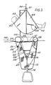
- the apparatus of Figures 1 to 3 comprises a miniature life raft or life buoy 1 having an irregular pentagon shape defining a "bow" 2 and a "transom” 3.
- the buoy is given its shape by a polyether-coated, nylon woven textile inflatable tube of circular cross-section when inflated and comprised of five generally straight sections 4, 5, 6, 7, 8 angularly joined together.
- the tube is arranged as a single compartment inflated from a pressurized gas bottle 9 on launch of the buoy.
- a pressure relief valve- not shown- is provided. In use, it is over the transom section 6 where a man overboard climbs, whilst the bow sections 4, 8 assist in supporting him semi-upright once aboard. Accordingly the transom section 6 has a smaller diameter whilst the bow sections 4, 8 have a larger diameter.
- the intervening sections 5, 7 taper between the larger and smaller diameters.
- a floor 10 Connecting between the lowermost (in the normal floating position) portions of the sections is a floor 10 of the same material as the tube.
- a connected invert cone 11 of similar, though lightly coated fabric, which forms a keel. It is provided with water ingress apertures 12 at its tip and is otherwise closed, in particular at its widest, upper part by being connected to the floor by welding, except that three small breather holes 13 are provided at the tip for drainage of water from the cone on retrieval of the buoy.
- a mass 14 having a fixed length or telescopic rigid rod 15 interconnecting the cone tip and the mass. The rod is rigid to ensure that on launch the mass remains outside the buoy and ultimately falls to its suspended position.
- the purpose of the mass is to extend the cone on launch. This causes the water to enter the cone through the apertures 12. These have inside, non-return valve, flaps 16 which act to prevent water egress as might otherwise occur if wind or waves were to lift the buoy above its normally floating height.
- the arrangement thus operates as a semi-rigid keel. (Water egress through the breather holes 13 is minimal during the buoy's movement in riding waves.)
- the vertical parts 17 of the ladder are of rope.
- the two rungs 18 are rigid.
- a pair of lines 17' connect the lower rung to the mass 14 to ensure that the rungs are pulled down on launch.
- Handles 21 are provided on the sections 5, 7.
- a water pocket 22 which is triangular in cross-section is secured to the underside of the floor at the bow. It has water ingress apertures towards the top of its sidewalls 23, fore and aft ones of which are closed together laterally of the buoy. Chain ballast 24 causes the pocket 22 to deploy for filling with water. When the man climbs the ladder, water in the pocket is lifted above the ambient water level and its weight tends to counterbalance the weight of the man.
- the buoy is provided with a drogue or sea anchor skirt 25 of open knitted nylon material.
- the skirt is in the form of a tube shackled to points 26 around the buoy and hanging down therefrom.
- the bottom of the skirt is gathered to a lightly weighted ring 27.
- a downwards extending opening in the skirt is provided at the steps 18 and the edges of the opening are attached to the ropes 17, whereby the skirt does not impede the ladder.
- the purpose of the drogue skirt is to assist the keel in preventing the buoy from being blown away from the man overboard before he can board it.
- the drogue skirt has a small cut out 25' at the bow to clear the water pocket 22 and the rope 33 (described below).
- the cone is circular in horizontal cross-section and supported in this shape by upper and lower rigid rings 28, 29 secured inside the cone.
- Other configurations are envisaged to be possible.
- the buoy is provided with a detachable sling 30 having a lifting eye 31 from which extend three webbing supports 40, 41, 42 to pass across the man's back at his shoulder blades, under his back side and behind his knees during lifting as shown in Figure 3. Between the webbing supports woven textile panels 43, 44 are provided. VELCRO (Registered trade mark) fastening strips 38, which normally retain the sling in position in the buoy, are provided on the sling and on the inflatable tube in positions shown in Figure 3.
- VELCRO Registered trade mark
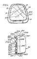
- the life buoy 1 is launched from a rigid cover 36.
- This is shown in Figures 4 and 5 and has two moulded plastics material parts 237, 238.
- the outer one 237 of these has a stepped lip 239 which accommodates the lip 240 of the other 238.
- a stainless steel bracket 241 supports the cover prior to use of the apparatus on a yacht's "push- pit" rails 242, 243.
- the bracket 241 has a generally L-shaped plate, the foot 245 of which carries the weight of the cover and engages the lip 239 at its lowest portion.
- the upright portion 246 of the plate carries a downwardly open hook 247 which engages over the lower rail 242.
- the portion 246 Towards its top edge 248, the portion 246 carries two welded-on, upright tubes 249 in which are accommodated the arms of an invert U rod 250.
- the U rod carries an upwardly open hook 251 which engages under the upper rail 243.
- the hooks 247, 251 are held apart for gripping the rails 242, 243 by screw knobs 252 threadedly engaging the arms of the U rod 250 through the tubes 249.
- the cover 36 is held back against the upright portion 246 of the L plate 244 by a strap 253 passing through a slot in the inner cover part 238 and secured to a bar 254 provided inside the outer cover part 237.
- the strap 253 has a buckle fitting 255 in which a tongue 256 of a release catch 257 engages.
- the tongue 257 projects in from a centrally pivoted catch lever 258, a spring biassing the tongue to remain engaged.
- the tongue 257 is withdrawn by a second lever 259 bearing on the end of the lever 258 opposite from the tongue.
- the second lever is also spring biassed and centrally pivoted. It has a release pull ring 260 secured to its end opposite from the lever 258. Thus pulling of the ring 260 away from the cover 36 moves the tongue 257 away and releases the buckle fitting 255.
- a gas release cord 261 passes out of an opening in the inner cover part 238 and is secured to the lower rail 242.
- the entire cover 36 falls away from the bracket 241 and hence its weight on the cord 261 withdraws a release pin (not shown) from the gas bottle 9.
- the cover is opened by initial expansion of gas into the tube 4, 5, 6,7, 8.
- the packing of the buoy into the cover 36 is such that the mass 14 falls free at an early stage and causes the invert cone keel 11 to deploy.
- the parts 237, 238 of the cover remain attached together and come to hang via a line 262 below the mass 14.
- the keel 11 is packed with negligible air within it and consequently fills substantially entirely with water.
- the steps 18 are deployed below the "stern" tube 6.
- the man overboard swims to the buoy and clambers aboard it, lies with his feet over the "stern" tube 6 and his head and shoulders supported on the "bow” tubes 4, 8.
- the sling 30 extends beneath him. For visibility the buoy has a self-erecting mast and flag 37.
- the line 34 When he is thus safely rescued, the line 34 is connected to a ring 35 on the floor 10 for lifting of the buoy from the water. Although the relatively small water pocket 22 remains full, the larger cone 11 drains slowly from the breather holes 13. To relieve the cone of the weight of the mass 14 on lifting, a line 39 is provided between the eye 35 and the upper end of the rod 15.
Landscapes
- Engineering & Computer Science (AREA)
- Mechanical Engineering (AREA)
- Ocean & Marine Engineering (AREA)
- Tents Or Canopies (AREA)
- Emergency Lowering Means (AREA)
- Chair Legs, Seat Parts, And Backrests (AREA)
Claims (15)
Applications Claiming Priority (4)
| Application Number | Priority Date | Filing Date | Title |
|---|---|---|---|
| GB858501540A GB8501540D0 (en) | 1985-01-22 | 1985-01-22 | Retrieval apparatus |
| GB8501540 | 1985-01-22 | ||
| GB8531577 | 1985-12-23 | ||
| GB858531577A GB8531577D0 (en) | 1985-12-23 | 1985-12-23 | Man overboard retrieval apparatus |
Publications (2)
| Publication Number | Publication Date |
|---|---|
| EP0248796A1 EP0248796A1 (de) | 1987-12-16 |
| EP0248796B1 true EP0248796B1 (de) | 1990-09-19 |
Family
ID=26288698
Family Applications (1)
| Application Number | Title | Priority Date | Filing Date |
|---|---|---|---|
| EP86900805A Expired - Lifetime EP0248796B1 (de) | 1985-01-22 | 1986-01-20 | Rettungsgerät zum bergen von schiffbrüchigen |
Country Status (5)
| Country | Link |
|---|---|
| US (1) | US4747797A (de) |
| EP (1) | EP0248796B1 (de) |
| AU (1) | AU582824B2 (de) |
| DE (1) | DE3674399D1 (de) |
| WO (1) | WO1986004312A1 (de) |
Families Citing this family (24)
| Publication number | Priority date | Publication date | Assignee | Title |
|---|---|---|---|---|
| US4968278A (en) * | 1989-05-02 | 1990-11-06 | Lemke Sharon A | Flotation platform |
| DE4012922A1 (de) * | 1990-04-23 | 1991-10-24 | Juergen Haro | Verfahren zum transport verletzter oder hilfloser und rettungskapsel zur durchfuehrung des verfahrens |
| US5408238A (en) * | 1993-03-17 | 1995-04-18 | Trimble Navigation Ltd. | Location of overboard person or object or of water-chemical interface |
| US5456426A (en) * | 1994-04-04 | 1995-10-10 | Lockheed Corporation | Attachment fitting for a wall of a flexible structure |
| US5687664A (en) * | 1996-04-10 | 1997-11-18 | Sofian; Terry N. | Foldable inflatable rescue pontoon |
| US5810695A (en) * | 1997-01-21 | 1998-09-22 | Sass; Randy J. | Water trampoline device |
| FI982732A7 (fi) * | 1998-12-17 | 2000-06-18 | Pohjois Savon Ammatillisen Kor | Pelastuslaite |
| WO2002094050A1 (en) * | 2001-05-22 | 2002-11-28 | Jens Kristian Mikkelsen | Sliding buckle for a rescue sling |
| USD518544S1 (en) * | 2005-05-05 | 2006-04-04 | Sportsstuff, Inc. | Inflatable towable water float |
| USD518132S1 (en) * | 2005-06-09 | 2006-03-28 | Sportsstuff, Inc. | Inflatable towable water float |
| US7585197B1 (en) | 2005-08-26 | 2009-09-08 | Merten C William | Crew overboard self rescue device and method for unassisted crew overboard watercraft reentry |
| US20090013574A1 (en) * | 2007-07-11 | 2009-01-15 | Palmer David E | Lightweight assistance requesting plackard |
| US7938229B2 (en) * | 2007-09-07 | 2011-05-10 | Davies Rebecca M | Marine emergency rope ladder apparatus |
| CN104024101A (zh) * | 2011-10-14 | 2014-09-03 | 里普博爱控股有限公司 | 安全浮标 |
| DE202012011525U1 (de) * | 2012-12-03 | 2013-01-29 | Christopher Fuhrhop | Überlebenshilfe, insbesondere für Schwimmer und Wassersportler |
| US8998666B1 (en) * | 2013-08-02 | 2015-04-07 | Steven Albright | Rescue method and system for an overboard passenger |
| US10286986B2 (en) | 2016-04-22 | 2019-05-14 | Christopher Ian Roxburgh Hugh | Bouyant inflatable device |
| RU2642201C1 (ru) * | 2016-08-17 | 2018-01-24 | Владимир Васильевич Чернявец | Надувной спасательный плот |
| US10814945B2 (en) * | 2017-12-08 | 2020-10-27 | Robert Chaney | Life raft system |
| US10435124B1 (en) * | 2018-04-25 | 2019-10-08 | Goodrich Corporation | Compartment ballast system |
| US11148765B2 (en) * | 2019-02-04 | 2021-10-19 | Frank Pieschel | Inflatable platform |
| US11497947B2 (en) | 2019-10-01 | 2022-11-15 | Roman Kushniruk | Rescue rig |
| US11548601B2 (en) | 2019-11-04 | 2023-01-10 | Crusoe Survival, Llc | Multi-chamber inflatable device |
| US12623758B2 (en) | 2019-11-04 | 2026-05-12 | Crusoe Survival, Llc | Multi-chamber inflatable device |
Family Cites Families (7)
| Publication number | Priority date | Publication date | Assignee | Title |
|---|---|---|---|---|
| BE535594A (de) * | ||||
| GB788338A (en) * | 1955-10-05 | 1957-12-23 | Frankenstein & Sons Manchester | Improvements in or relating to inflatable life-rafts |
| GB864586A (en) * | 1958-10-30 | 1961-04-06 | Cecil Hugh Latimer Needham | Improvements relating to inflatable liferafts |
| GB1059424A (en) * | 1965-01-11 | 1967-02-22 | Rfd Co Ltd | Improvements in or relating to inflatable dinghies |
| SE323904B (de) * | 1966-05-26 | 1970-05-11 | Scheibert Dt Schlauchbootfab | |
| FR2040867A5 (de) * | 1969-04-16 | 1971-01-22 | Angeviniere Joue Les Tou | |
| US4533333A (en) * | 1980-08-08 | 1985-08-06 | The United States Of America As Represented By The Secretary Of The Navy | Helicopter extractable cold weather/water liferaft |
-
1986
- 1986-01-20 EP EP86900805A patent/EP0248796B1/de not_active Expired - Lifetime
- 1986-01-20 WO PCT/GB1986/000036 patent/WO1986004312A1/en not_active Ceased
- 1986-01-20 US US06/912,336 patent/US4747797A/en not_active Expired - Fee Related
- 1986-01-20 AU AU53563/86A patent/AU582824B2/en not_active Ceased
- 1986-01-20 DE DE8686900805T patent/DE3674399D1/de not_active Expired - Lifetime
Also Published As
| Publication number | Publication date |
|---|---|
| US4747797A (en) | 1988-05-31 |
| EP0248796A1 (de) | 1987-12-16 |
| WO1986004312A1 (en) | 1986-07-31 |
| AU5356386A (en) | 1986-08-13 |
| DE3674399D1 (de) | 1990-10-25 |
| AU582824B2 (en) | 1989-04-13 |
Similar Documents
| Publication | Publication Date | Title |
|---|---|---|
| US4747797A (en) | Man overboard retrieval apparatus | |
| AU634703B2 (en) | A parasailing assembly and system for launching the same | |
| WO1994001324A1 (en) | Improvement of life rafts on ships | |
| US5257954A (en) | Rescue buoy package | |
| US5468167A (en) | Life raft utility tether | |
| US5370565A (en) | Rescue net and method for rapidly moving water | |
| JPH03284498A (ja) | ネット状救命機器 | |
| US4823724A (en) | Bumper storage system | |
| EP2200896A1 (de) | Mann-über-bord-rettungsvorrichtung | |
| US6038994A (en) | Small boat support and rigging apparatus and method of use | |
| EP0929438B1 (de) | Seenotrettungsgerät | |
| US4986785A (en) | Lifeline strap apparatus | |
| US3222700A (en) | Inflatable liferafts | |
| US6769378B1 (en) | Portable self-rescue device for kayakers | |
| DE102014000649B4 (de) | Komposit-Rettungsinsel zur Evakuierung, Sicherung und Rettung von schiffbrüchigen Personen | |
| US2270437A (en) | Life saving device | |
| EP1336560B1 (de) | Seerettungsgerät | |
| CA1285828C (en) | Man overboard retrieval apparatus | |
| US6953374B1 (en) | Man overboard retrieval device | |
| GB2144710A (en) | A device for raising a person or object | |
| RU2114759C1 (ru) | Черпак | |
| GB2284391A (en) | Recovery of persons overboard | |
| WO1988001586A1 (en) | A marine aid for marine craft | |
| JP2543367B2 (ja) | 船舶用救助袋 | |
| JP2500320B2 (ja) | 救命筏用装着式耐氷設備 |
Legal Events
| Date | Code | Title | Description |
|---|---|---|---|
| PUAI | Public reference made under article 153(3) epc to a published international application that has entered the european phase |
Free format text: ORIGINAL CODE: 0009012 |
|
| 17P | Request for examination filed |
Effective date: 19870801 |
|
| AK | Designated contracting states |
Kind code of ref document: A1 Designated state(s): DE FR GB IT NL SE |
|
| 17Q | First examination report despatched |
Effective date: 19890424 |
|
| RAP3 | Party data changed (applicant data changed or rights of an application transferred) |
Owner name: HINDLE, JOHN DOUGLAS |
|
| GRAA | (expected) grant |
Free format text: ORIGINAL CODE: 0009210 |
|
| AK | Designated contracting states |
Kind code of ref document: B1 Designated state(s): DE FR GB IT NL SE |
|
| PG25 | Lapsed in a contracting state [announced via postgrant information from national office to epo] |
Ref country code: IT Free format text: LAPSE BECAUSE OF FAILURE TO SUBMIT A TRANSLATION OF THE DESCRIPTION OR TO PAY THE FEE WITHIN THE PRE;WARNING: LAPSES OF ITALIAN PATENTS WITH EFFECTIVE DATE BEFORE 2007 MAY HAVE OCCURRED AT ANY TIME BEFORE 2007. THE CORRECT EFFECTIVE DATE MAY BE DIFFERENT FROM THE ONE RECORDED.SCRIBED TIME-LIMIT Effective date: 19900919 Ref country code: SE Effective date: 19900919 Ref country code: NL Effective date: 19900919 |
|
| REF | Corresponds to: |
Ref document number: 3674399 Country of ref document: DE Date of ref document: 19901025 |
|
| ET | Fr: translation filed | ||
| PGFP | Annual fee paid to national office [announced via postgrant information from national office to epo] |
Ref country code: GB Payment date: 19910129 Year of fee payment: 6 |
|
| PGFP | Annual fee paid to national office [announced via postgrant information from national office to epo] |
Ref country code: FR Payment date: 19910131 Year of fee payment: 6 |
|
| PGFP | Annual fee paid to national office [announced via postgrant information from national office to epo] |
Ref country code: DE Payment date: 19910215 Year of fee payment: 6 |
|
| NLV1 | Nl: lapsed or annulled due to failure to fulfill the requirements of art. 29p and 29m of the patents act | ||
| PLBE | No opposition filed within time limit |
Free format text: ORIGINAL CODE: 0009261 |
|
| STAA | Information on the status of an ep patent application or granted ep patent |
Free format text: STATUS: NO OPPOSITION FILED WITHIN TIME LIMIT |
|
| 26N | No opposition filed | ||
| PG25 | Lapsed in a contracting state [announced via postgrant information from national office to epo] |
Ref country code: GB Effective date: 19920120 |
|
| REG | Reference to a national code |
Ref country code: GB Ref legal event code: PCNP |
|
| PG25 | Lapsed in a contracting state [announced via postgrant information from national office to epo] |
Ref country code: FR Effective date: 19920930 |
|
| PG25 | Lapsed in a contracting state [announced via postgrant information from national office to epo] |
Ref country code: DE Effective date: 19921001 |
|
| REG | Reference to a national code |
Ref country code: FR Ref legal event code: ST |