EP0248582A2 - Transmission différentielle - Google Patents
Transmission différentielle Download PDFInfo
- Publication number
- EP0248582A2 EP0248582A2 EP87304632A EP87304632A EP0248582A2 EP 0248582 A2 EP0248582 A2 EP 0248582A2 EP 87304632 A EP87304632 A EP 87304632A EP 87304632 A EP87304632 A EP 87304632A EP 0248582 A2 EP0248582 A2 EP 0248582A2
- Authority
- EP
- European Patent Office
- Prior art keywords
- shaft
- case
- differential gear
- shafts
- gear
- Prior art date
- Legal status (The legal status is an assumption and is not a legal conclusion. Google has not performed a legal analysis and makes no representation as to the accuracy of the status listed.)
- Granted
Links
Images


Classifications
-
- F—MECHANICAL ENGINEERING; LIGHTING; HEATING; WEAPONS; BLASTING
- F16—ENGINEERING ELEMENTS AND UNITS; GENERAL MEASURES FOR PRODUCING AND MAINTAINING EFFECTIVE FUNCTIONING OF MACHINES OR INSTALLATIONS; THERMAL INSULATION IN GENERAL
- F16H—GEARING
- F16H48/00—Differential gearings
- F16H48/20—Arrangements for suppressing or influencing the differential action, e.g. locking devices
- F16H48/30—Arrangements for suppressing or influencing the differential action, e.g. locking devices using externally-actuatable means
-
- B—PERFORMING OPERATIONS; TRANSPORTING
- B60—VEHICLES IN GENERAL
- B60K—ARRANGEMENT OR MOUNTING OF PROPULSION UNITS OR OF TRANSMISSIONS IN VEHICLES; ARRANGEMENT OR MOUNTING OF PLURAL DIVERSE PRIME-MOVERS IN VEHICLES; AUXILIARY DRIVES FOR VEHICLES; INSTRUMENTATION OR DASHBOARDS FOR VEHICLES; ARRANGEMENTS IN CONNECTION WITH COOLING, AIR INTAKE, GAS EXHAUST OR FUEL SUPPLY OF PROPULSION UNITS IN VEHICLES
- B60K17/00—Arrangement or mounting of transmissions in vehicles
- B60K17/04—Arrangement or mounting of transmissions in vehicles characterised by arrangement, location, or kind of gearing
- B60K17/16—Arrangement or mounting of transmissions in vehicles characterised by arrangement, location, or kind of gearing of differential gearing
- B60K17/20—Arrangement or mounting of transmissions in vehicles characterised by arrangement, location, or kind of gearing of differential gearing in which the differential movement is limited
-
- B—PERFORMING OPERATIONS; TRANSPORTING
- B60—VEHICLES IN GENERAL
- B60K—ARRANGEMENT OR MOUNTING OF PROPULSION UNITS OR OF TRANSMISSIONS IN VEHICLES; ARRANGEMENT OR MOUNTING OF PLURAL DIVERSE PRIME-MOVERS IN VEHICLES; AUXILIARY DRIVES FOR VEHICLES; INSTRUMENTATION OR DASHBOARDS FOR VEHICLES; ARRANGEMENTS IN CONNECTION WITH COOLING, AIR INTAKE, GAS EXHAUST OR FUEL SUPPLY OF PROPULSION UNITS IN VEHICLES
- B60K17/00—Arrangement or mounting of transmissions in vehicles
- B60K17/34—Arrangement or mounting of transmissions in vehicles for driving both front and rear wheels, e.g. four wheel drive vehicles
- B60K17/344—Arrangement or mounting of transmissions in vehicles for driving both front and rear wheels, e.g. four wheel drive vehicles having a transfer gear
- B60K17/346—Arrangement or mounting of transmissions in vehicles for driving both front and rear wheels, e.g. four wheel drive vehicles having a transfer gear the transfer gear being a differential gear
- B60K17/3462—Arrangement or mounting of transmissions in vehicles for driving both front and rear wheels, e.g. four wheel drive vehicles having a transfer gear the transfer gear being a differential gear with means for changing distribution of torque between front and rear wheels
-
- B—PERFORMING OPERATIONS; TRANSPORTING
- B60—VEHICLES IN GENERAL
- B60K—ARRANGEMENT OR MOUNTING OF PROPULSION UNITS OR OF TRANSMISSIONS IN VEHICLES; ARRANGEMENT OR MOUNTING OF PLURAL DIVERSE PRIME-MOVERS IN VEHICLES; AUXILIARY DRIVES FOR VEHICLES; INSTRUMENTATION OR DASHBOARDS FOR VEHICLES; ARRANGEMENTS IN CONNECTION WITH COOLING, AIR INTAKE, GAS EXHAUST OR FUEL SUPPLY OF PROPULSION UNITS IN VEHICLES
- B60K23/00—Arrangement or mounting of control devices for vehicle transmissions, or parts thereof, not otherwise provided for
- B60K23/04—Arrangement or mounting of control devices for vehicle transmissions, or parts thereof, not otherwise provided for for differential gearing
-
- B—PERFORMING OPERATIONS; TRANSPORTING
- B60—VEHICLES IN GENERAL
- B60K—ARRANGEMENT OR MOUNTING OF PROPULSION UNITS OR OF TRANSMISSIONS IN VEHICLES; ARRANGEMENT OR MOUNTING OF PLURAL DIVERSE PRIME-MOVERS IN VEHICLES; AUXILIARY DRIVES FOR VEHICLES; INSTRUMENTATION OR DASHBOARDS FOR VEHICLES; ARRANGEMENTS IN CONNECTION WITH COOLING, AIR INTAKE, GAS EXHAUST OR FUEL SUPPLY OF PROPULSION UNITS IN VEHICLES
- B60K23/00—Arrangement or mounting of control devices for vehicle transmissions, or parts thereof, not otherwise provided for
- B60K23/08—Arrangement or mounting of control devices for vehicle transmissions, or parts thereof, not otherwise provided for for changing number of driven wheels, for switching from driving one axle to driving two or more axles
- B60K23/0808—Arrangement or mounting of control devices for vehicle transmissions, or parts thereof, not otherwise provided for for changing number of driven wheels, for switching from driving one axle to driving two or more axles for varying torque distribution between driven axles, e.g. by transfer clutch
-
- F—MECHANICAL ENGINEERING; LIGHTING; HEATING; WEAPONS; BLASTING
- F16—ENGINEERING ELEMENTS AND UNITS; GENERAL MEASURES FOR PRODUCING AND MAINTAINING EFFECTIVE FUNCTIONING OF MACHINES OR INSTALLATIONS; THERMAL INSULATION IN GENERAL
- F16H—GEARING
- F16H48/00—Differential gearings
- F16H48/06—Differential gearings with gears having orbital motion
- F16H48/08—Differential gearings with gears having orbital motion comprising bevel gears
-
- F—MECHANICAL ENGINEERING; LIGHTING; HEATING; WEAPONS; BLASTING
- F16—ENGINEERING ELEMENTS AND UNITS; GENERAL MEASURES FOR PRODUCING AND MAINTAINING EFFECTIVE FUNCTIONING OF MACHINES OR INSTALLATIONS; THERMAL INSULATION IN GENERAL
- F16H—GEARING
- F16H48/00—Differential gearings
- F16H48/36—Differential gearings characterised by intentionally generating speed difference between outputs
-
- F—MECHANICAL ENGINEERING; LIGHTING; HEATING; WEAPONS; BLASTING
- F16—ENGINEERING ELEMENTS AND UNITS; GENERAL MEASURES FOR PRODUCING AND MAINTAINING EFFECTIVE FUNCTIONING OF MACHINES OR INSTALLATIONS; THERMAL INSULATION IN GENERAL
- F16H—GEARING
- F16H59/00—Control inputs to control units of change-speed-, or reversing-gearings for conveying rotary motion
- F16H59/50—Inputs being a function of the status of the machine, e.g. position of doors or safety belts
- F16H59/58—Inputs being a function of the status of the machine, e.g. position of doors or safety belts dependent on signals from the steering
-
- F—MECHANICAL ENGINEERING; LIGHTING; HEATING; WEAPONS; BLASTING
- F16—ENGINEERING ELEMENTS AND UNITS; GENERAL MEASURES FOR PRODUCING AND MAINTAINING EFFECTIVE FUNCTIONING OF MACHINES OR INSTALLATIONS; THERMAL INSULATION IN GENERAL
- F16H—GEARING
- F16H48/00—Differential gearings
- F16H48/20—Arrangements for suppressing or influencing the differential action, e.g. locking devices
- F16H2048/204—Control of arrangements for suppressing differential actions
- F16H2048/205—Control of arrangements for suppressing differential actions using the steering as a control parameter
-
- F—MECHANICAL ENGINEERING; LIGHTING; HEATING; WEAPONS; BLASTING
- F16—ENGINEERING ELEMENTS AND UNITS; GENERAL MEASURES FOR PRODUCING AND MAINTAINING EFFECTIVE FUNCTIONING OF MACHINES OR INSTALLATIONS; THERMAL INSULATION IN GENERAL
- F16H—GEARING
- F16H48/00—Differential gearings
- F16H48/36—Differential gearings characterised by intentionally generating speed difference between outputs
- F16H2048/364—Differential gearings characterised by intentionally generating speed difference between outputs using electric or hydraulic motors
-
- F—MECHANICAL ENGINEERING; LIGHTING; HEATING; WEAPONS; BLASTING
- F16—ENGINEERING ELEMENTS AND UNITS; GENERAL MEASURES FOR PRODUCING AND MAINTAINING EFFECTIVE FUNCTIONING OF MACHINES OR INSTALLATIONS; THERMAL INSULATION IN GENERAL
- F16H—GEARING
- F16H48/00—Differential gearings
- F16H48/38—Constructional details
- F16H48/40—Constructional details characterised by features of the rotating cases
Definitions
- This invention relates to a differential gear and, more particularly, to a differential gear used suitably for a differential gear installed in a drive line of a vehicle to drive front or rear wheels and a center differential gear of a four wheel drive car.
- driving force transmitting capacity is structurally limited. In this case, sufficient driving force cannot be transmitted.
- An object of the present invention is to provide a differential gear which one of a plurality of wheels connected to a drive line having the differential gear never slips.
- Another object of the present invention is to provide a differential gear which dispenses with a differential lock or a limited slip differential.
- a further object of the present invention is to provide a differential gear which dispenses with any operation by a driver.
- a differential gear comprises a rotatable case, pinions disposed rotatably in the case, a pair of side gears meshing with the pinions and disposed rotatably in said case, a first shaft supported rotatably about a rotary axis of said case and extending from one of said side gears, a second shaft supported rotatably about said axis and extending from the other side gear in the opposite direction to said first shaft, a driven means provided in one of said first and second shafts, a first means for rotating said driven means to give driving force to said first and second shafts, a worm wheel provided in said case, a second rotary means having a worm meshing with the worm wheel and a control device for controlling number of revolutions of said second rotary means to maintain the difference between number of revolutions of said first shaft and that of said second shaft within a predetermined range.
- the control device is a CPU or a computer for calculating on the basis of signals from a steering angle sensor and a vehicle speed sensor to control the number of revolutions of the second rotary means.
- a driven means is fixed to said case, and a worm wheel is provided in one of the first and second shafts.
- the first and second shafts are respectively connected to the drive wheels.
- the worm wheel is rotated by the second rotary means at the number of revolutions same as or slight higher than that of the case at the time of straight driving.
- the drive wheel does not slip because there never occurs substantial difference of number of revolutions between the first or second shaft having the worm wheel and the case.
- the worm wheel is always rotated at the number of revolutions corresponding to a vehicle speed.
- the second rotary means needs only a small torque capacity for rotating the worm wheel because driving torque required for running the vehicle is transmitted to the first and second shafts through the first rotary means, driven means and case.
- the control device calculates the difference between the number of revolutions of the drive wheel located at an outside of turning and that of the drive wheel located at an inside of turning from a steering angle and vehicle speed at the time of turning of the vehicle and controls the second rotary means to give the difference to both drive wheels.
- one of said first and second shafts is connected to a propeller shaft at the front side and the other to a propeller shaft at the rear side.
- the control device calculates the difference between the numbers of revolutions of the propeller shafts at the front and rear sides from a steering angle and vehicle speed at the time of turning of the vehicle and controls the second rotary means to give the difference to the propeller shafts at both sides.
- the differential gear is provided with original driven means and first rotary means and further the worm wheel and second rotary means which has the worm and operates independently of said first rotary means, and the difference between the numbers of revolutions of the first and second shafts is held substantially zero at the time of straight driving and held within a predetermined range at the time of turning, one of a plurality of drive wheels is prevented from slipping. Also, smooth turning can be ensured.
- a differential gear 30 shown in Figs. 1 and 2 comprises a case 32, pinion gears 34 and side gears 36 disposed respectively in the case 32.
- the case 32 is a so-called differential case which is disposed in a differential carrier 38 and supported rotatably by a pair of roller bearings 40 attached to the differential carrier 38.
- At least one pinion shaft is fixed in the case 32.
- two short pinion shafts 43 are disposed orthogonally to a long pinion shaft 42. These pinion shafts have their axes arranged orthogonally to a rotary axis of the case 32.
- the long pinion shaft 42 and short pinion shafts 43 are rotatably supported a pair of pinions 34 axially spaced from each other.
- two pinions 34 are rotatably supported by the pinion shaft.
- Two side gears 36 are disposed in the case 32 and spaced from each other to mesh with four pinions 34 respectively.
- a first shaft 44 is connected through serrations with one side gear 36 and extends from the case 32 in one direction.
- the shaft 44 projects from the differential carrier 38.
- the shaft 44 is supported through a boss 37 of the side gear 36 by a shoulder of the case 32 and through a first driven means which will be later described by a pair of bearings 46, said shaft 44 being rotatable about the rotary axis of the case 32.
- a second shaft 48 is connected through serrations with the other side gear 36 and extends from the case 32 in the opposite direction to the first shaft 44.
- the shaft 48 projects from the differential carrier 38.
- the shaft 48 is supported through a boss 37 of the other side gear 36 by a shoulder of the case 32 and by bearings (not shown), said shaft 48 being rotatable about the rotary axis of the case 32.
- a first driven means 50 is provided in one of the case 32, the first shaft 44 and the second shaft 48.
- the driven means 50 is a spur gear which connected through serrations with the first shaft 44.
- the pair of roller bearings 46 are attached between bosses 51 protruding from both sides of the spur gear 50 and the differential carrier 38, the spur gear 50 being rotatable about the same axis as the first shaft 44.
- a first rotary means which will be later described engages with the first driven means 50, both means giving driving force to the first and second shafts 44,48.
- a second driven means 52 is provided in one of the case 32, the first shaft 44 and the second shaft 48 which is not provided with the first driven means 50.
- the second driven means 52 is a worm wheel which is fixed in the case 32 by press fitting or threading engagement well known per se.
- a second means 54 for rotating the second driven means 52 comprises a worm 55 which is rotatably supported by the differential carrier 38.
- an electric motor 56 is mounted on the differential carrier 38 and a shaft of the worm 55 is connected through serrations with an output shaft 57 of the motor 56.
- control device calculates number of revolutions and direction of rotation of the second rotary means 54 on the basis of these signals and controls the same to maintain the difference between the numbers of revolutions of the first and second shafts 44,48 within a predetermined range including zero.
- a differential gear 60 shown in Fig. 3 is similar in its basic constitution to that of the differential gear 30 shown in Figs. 1 and 2. That is, the differential gear 60 comprises the case 32 supported rotatable by the differential carrier 38, pinions 34 supported rotatably by the pinion shaft 42 disposed in the case 32 and a pair of side gears 36 disposed in the case 32 to mesh with the pinions 34.
- the differential gear 60 further comprises the first shaft 44 extending from one side gear 36 and the second shaft 48 extending from the other side gear 36 in the opposite direction to the first shaft 44.
- a first driven means 62 is formed of a spur gear fixed to the case 32 by bolts 64.
- the first driven means 62 is rotated by a first rotary means to give driving force to the first and second shafts 44,48.
- a second driven means 66 is formed of a worm wheel which is connected through serrations with the first shaft 44.
- the worm wheel 66 is rotated by a worm 68 included in a second rotary means to maintain the difference between the numbers of revolutions of the first and second shafts 44,48 within a predetermined range.
- the case 32 is rotated at the time of straight driving and the worm wheel 66 is also rotated at the number of revolutions same as or slight higher than that of the case 32.
- the worm wheel 66 is rotated at the number of revolutions which gives the required difference between the number of revolutions of the first shaft 44 and that of the second shaft 48.
- frictions between pinions 34 and the pinion shaft 42 and between the pinions 34 and the side gears 36 can be reduced.
- a differential gear 70 shown in Fig. 4 is similar in its basic constitution to those of the differential gears 30,60 shown in Figs. 1 to 3. That is, the differential gear 70 comprises the case 32 supported rotatably by the differential carrier 38, pinions 34 rotatably supported by the pinion shaft 42 disposed in the case 32 and a pair of side gears 38 disposed in the case 32 to mesh with the pinions 34.
- the differential gear 70 further comprises the first shaft 44 extending from one side gear 36 and the second shaft 48 extending from the other side gear 36 in the opposite direction to the first shaft 44, while differing from said differential gears 30,60 in the following points:
- the first shaft 44 is formed integrally with a boss 72.
- a bevel gear 74 of the first driven means is fixed to the boss 72 by bolts 76.
- the bevel gear 74 meshes with a small bevel gear 78 of the first rotary means to transmit driving force to the first and second shafts 44,48.
- An auxiliary second gear device 80 is provided in relation to the second shaft 48 of the differential gear 70.
- the driving force is transmitted to the first and second shafts 44,48, respectively through the first rotary means 78 meshing with the first driven means 74 as mentioned above. Therefore, the second shaft 48 is rotated reversely to the first shaft 44.
- the rotational direction of the second shaft 48 has to be similar to that of the first shaft 44.
- the auxiliary gear device 80 fulfills this function.
- the second gear device 80 does not have any rotatable case and a pinion shaft 82 is fixed to the differential carrier 38.
- Two pinions 84 are disposed in the differential carrier 38 to be rotatably supported by the pinion shaft 82.
- a pair of side gears 86,88 are disposed in the differential carrier 38 to mesh with the pinions 84.
- a first portion 49a of the second shaft 48 projects integrally from one side gear 86 to be connected through serrations with the side gear 36 of the differential gear 70.
- a second portion 49b of the second shaft 48 is connected through serrations with the other side gear 88 to project from the differential carrier 38.
- the second driven means 52 is formed of a worm wheel fixed to the case 32. Thw worm wheel 52 is rotated by the worm 55 included in the second rotary means to maintain the difference between the numbers of revolutions of the first and second shafts 44,48 within a predetermined range.
- Said differential gears are used in various forms.
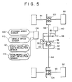
- the differential carrier 38 is fixed to a car body between front wheels 90 and rear wheels 92 and the first shaft of the differential gear 30 is connected to a front propeller shaft 94 and the second shaft to a rear propeller shaft 96.
- a spur gear 98 included in the first rotary means is connected to a transmission 100 to mesh with the spur gear of the first driven means 50.
- a front differential gear 102 is incorporated in a drive shaft 91 of the front wheels 90 and a rear differential gear 104 in a drive shaft 93 of the rear wheels 92, respectively.
- the front differential gear 102 is connected to the front propeller shaft 94 and the rear differential gear 104 to the rear propeller shaft 96, respectively.
- driving force from the transmission 100 is, on one hand, transmitted from the first driven means 50 to the front wheels 90 through the front propeller shaft 94, front differential gear 102 and drive shaft 91 and, on the other hand, transmitted from the first driven means 50 to the rear wheels 92 through the differential gear 30, rear propeller shaft 96, rear differential gear 104 and drive shaft 93.
- a control device 106 is a computer or a CPU which receives signals from a steering angle sensor 108 and a vehicle speed sensor 110 well known per se.
- the steering angle sensor 108 detects the size of angle and steering direction.
- the control device 106 receives signals from a front propeller shaft revolution speed sensor 112 and a rear propeller shaft revolution speed sensor 114 to carry out feed-back control.
- the control device 106 executes calculation which will be later described and controls the number of revolutions and direction of rotation of the motor 56.
- the electric motor 56 arranged as shown in Fig. 5 is controlled so as to reduce the number of revolutions of the rear propeller shaft 96, so that loss in controlling can be eliminated.
- Fig. 6 showing schematically the embodiment, in which the differential gear 30 is used for a front differential gear in a front wheel drive car, the differential gear 30 is interposed between the front wheels 90,90.
- a spur gear 116 is fixed to the first shaft 44 of the differential gear 30.
- a spur gear 120 is fixed to a left drive shaft 118 to mesh with the spur gear 116.
- the numbers of teeth of both spur gears are equal to each other, so that the rotation of the first shaft 44 is reversed and taken out to the left drive shaft 118.
- a sprocket or pulley 122 is fixed to the second shaft 48 of the differential gear 30.
- a sprocket or pulley 126 is fixed to a right drive shaft 124.
- a chain or belt 128 is trained over the second shaft 48 and the right drive shaft 124.
- the spur gear 98 included in the first rotary means is connected to the transmission 100 to mesh with the spur gear of the first driven means 50.
- power from the transmission 100 is transmitted to the left front wheel 90 through a pair of spur gears 116,120 and left drive shaft 118 on one hand and to the right fromt wheel 90 through the differential gear 30, chain or belt 128 and right drive shaft 124 on the other hand.
- the control device 106 receives signals from the steering angle sensor 108 and vehicle speed sensor 110 to control the number of revolutions and directions of rotation of the motor 56.
- the rotation of the first shaft 44 of the differential gear 30 is reversed to transmit to the left drive shaft 118.
- the auxiliary gear device 80 is incorporated in the second shaft 48 and the rotation of the first shaft 44 is reversed to transmit to the second shaft 48. Therefore, as mentioned above, the differential gear 70 can be used for the front or rear differential gear as it is.
- Fig. 7 showing schematically the embodiment, in which two differential gears 30 are used for front and rear differential gears in a four wheel drive car and an ordinary differential gear is used for a center differential gear 130, the differential carrier of the front side differential gear 30 and the differential carrier of the rear side differential gear 30 are respectively disposed between the front wheels 90,90 and between the rear wheels 132,132 to be fixed to the car body.
- a bevel gear 134 included in the first rotary means is connected to a shaft 136 of the differential gear 130 and to the transmission 100 through the differential gear 130.
- the first driven means 50 is a bevel gear meshing with the bevel gear 134.
- a spur gear 140 is fixed to the first shaft 44 of the rear side differential gear 30.
- a spur gear 144 is fixed to the right drive shaft 142 to mesh with the spur gear 140.
- the number of teeth of the spur gear 140 is equal to that of the spur gear 142, thereby being reversed the rotation of the first shaft 44 to be taken out to the right drive shaft 142.
- a sprocket or pulley 146 is fixed to the second shaft 48 of the rear side differential gear 30.
- a sprocket or pulley 150 is fixed to a left drive shaft 148, a chain or belt 152 being trained over the second shaft 48 and the left drive shaft 148.
- a bevel gear 154 included in the first rotary means is connected to a shaft 156 of the differential gear 130 and to the transmission 100 through the differential gear 130.
- the first driven means 50 is a bevel gear meshing with the bevel gear 154.
- the control device 106 calculates on the basis of signals from the steering angle sensor 108 and vehicle speed sensor 110.
- the device controls the number of revolutions of the motor 56 for the front side differential gear 30 to maintain the difference between the numbers of revolutions of the left and right front drive shafts 118,124 within a predetermined range.
- the device 106 also controls the number of revolutions of the motor 56 for the rear side differential gear 30 to maintain the difference between the numbers of revolutions of the left and right rear drive shafts 148,142 within a predetermined range.
- Fig. 8 showing schematically the embodiment, in which the differential gear 70 is modified in that the auxiliary gear device 80 is provided in relation with the first shaft 44 and the differential gear 70 is used for a rear differential gear.
- Driving force transmitted from a propeller shaft 156 is transmitted to the first shaft 44 through bevel gears 78,72 on one hand and to the second shaft 48 through the auxiliary gear device 80 on the other hand in which the rotation of the first shaft 44 is reversed to be taken out to the second shaft 48.
- the control device 106 receives signals from the steering angle sensor 108 and vehicle speed sensor 110. The device calculates the difference between the numbers of revolutions of the first and second shafts 44,48 and controls the motor 56.
- the calculation in the control device is carried out by properly using the following formulas.
- the number of revolutions of the front propeller shaft is set as N1, a wheel base of the vehicle as l, a wheel tread as m, a tire turning angle as ⁇ and the final reduction ratio of the front side differential gear as i1.
- the number of revolution N1 and the tire turning angle ⁇ respectively from the vehicle speed sensor and steering angle sensor.
- the average turning radius R1(OB) of the front wheels, average turning radius R2(OA) of the rear wheels, turning radius R11(OC) of a front inner wheel, turning radius R12(OD) of a front outer wheel, turning radius R21(OE) of a rear inner wheel and turning radius R22(OF) of a rear outer wheel are given as shown in Fig. 9.
- the number of revolutions n21 of the rear inner wheel is obtained as follows; from the following relationship
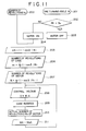
- control device 106 controls as shown in Fig. 11.
- the number of revolutions N1 is detected (200) from the vehicle speed sensor 110 and the tire turning angle ⁇ is detected (201) from the steering angle sensor 108.
- the tire turning angle ⁇ is compared with a predetermined value ⁇ o to judge (202) whether or not the turning angle ⁇ exceeds a play range of a steering wheel.
- the operation of the motor 56 is stopped (203) and when the turning angle ⁇ exceeds the play range, the motor 56 is operated (204).
- the difference ⁇ N between numbers of revolutions of the front and rear propeller shafts is obtained (205) from the number of revolutions N1 to calculate the number of revolutions n o of the case 32 (206).
- the number of revolutions M of the motor is obtained from the reduction ratio i of the worm wheel 52 and worm 55 and the number of revolutions of the case (207).
- Control voltage V is calculated by the use of a constant A (208).
- the case 32 is rotated (209) on the basis of the control voltage V and the actual number of revolutions M o of the motor 56 is detected (210).
- the difference between the theoretical voltage value and the detected voltage value is obtained (211) to feed back it as the control voltage V.
- the second driven means is the worm wheel 52 and the second rotary means includes the worm 55 so that the worm wheel 52 can be rotated by the worm 55.
- the reverse operation i.e., the rotation of the worm 55 by the worm wheel 52, is impossible according to the property of the worm 55.
- the differential gear 30 is securely controlled by the number of revolutions and directions of rotation of the motor 56.
Applications Claiming Priority (4)
| Application Number | Priority Date | Filing Date | Title |
|---|---|---|---|
| JP119060/86 | 1986-05-26 | ||
| JP61119060A JP2545796B2 (ja) | 1986-05-26 | 1986-05-26 | 差動装置 |
| JP120140/86 | 1986-05-27 | ||
| JP12014086A JPH0825396B2 (ja) | 1986-05-27 | 1986-05-27 | 差動装置 |
Publications (4)
| Publication Number | Publication Date |
|---|---|
| EP0248582A2 true EP0248582A2 (fr) | 1987-12-09 |
| EP0248582A3 EP0248582A3 (en) | 1989-05-10 |
| EP0248582B1 EP0248582B1 (fr) | 1992-08-05 |
| EP0248582B2 EP0248582B2 (fr) | 1995-04-05 |
Family
ID=26456861
Family Applications (1)
| Application Number | Title | Priority Date | Filing Date |
|---|---|---|---|
| EP87304632A Expired - Lifetime EP0248582B2 (fr) | 1986-05-26 | 1987-05-26 | Transmission différentielle |
Country Status (3)
| Country | Link |
|---|---|
| US (1) | US4813297A (fr) |
| EP (1) | EP0248582B2 (fr) |
| DE (1) | DE3780871T2 (fr) |
Cited By (6)
| Publication number | Priority date | Publication date | Assignee | Title |
|---|---|---|---|---|
| FR2629779A1 (fr) * | 1988-01-11 | 1989-10-13 | Honda Motor Co Ltd | |
| GB2219363A (en) * | 1988-04-22 | 1989-12-06 | Tochigi Fuji Sangyo Kk | Differential gearing having action influenced by electric motor |
| EP0493206A1 (fr) * | 1990-12-28 | 1992-07-01 | ETAT FRANCAIS Représenté par le délÀ©gué général pour l'armement | Véhicule à direction mixte |
| FR2674194A1 (fr) * | 1991-03-20 | 1992-09-25 | Peugeot | Procede de controle de la vitesse de rotation des roues d'un vehicule automobile dans les virages et dispositif pour sa mise en óoeuvre. |
| EP0575151A1 (fr) * | 1992-06-15 | 1993-12-22 | Mitsubishi Jidosha Kogyo Kabushiki Kaisha | Dispositif de répartition de force motrice entre les roues droites et gauches d'un véhicule |
| FR2844225A1 (fr) * | 2002-09-07 | 2004-03-12 | Bosch Gmbh Robert | Boite transfert pour vehicules et procede pour repartir une force d'entrainement sur deux essieux |
Families Citing this family (9)
| Publication number | Priority date | Publication date | Assignee | Title |
|---|---|---|---|---|
| JPH0815851B2 (ja) * | 1987-10-09 | 1996-02-21 | 日産自動車株式会社 | 差動制限装置 |
| JPH0761779B2 (ja) * | 1988-03-14 | 1995-07-05 | 本田技研工業株式会社 | 車両の前後輪駆動装置 |
| US6835154B2 (en) * | 1999-10-15 | 2004-12-28 | New Venture Gear, Inc. | On-demand transfer case |
| US6645112B1 (en) * | 1999-10-15 | 2003-11-11 | New Venture Gear, Inc. | On-demand transfer case |
| US6402652B1 (en) * | 1999-10-15 | 2002-06-11 | New Venture Gear, Inc. | Continuously variable four-wheel drive transmission with traction control |
| US6427797B1 (en) * | 2001-02-07 | 2002-08-06 | Hui-Lung Chang | Transmission structure of gearbox of electrically actuated car |
| KR100717306B1 (ko) * | 2005-12-09 | 2007-05-15 | 현대자동차주식회사 | 하이브리드 차량용 동력전달장치 |
| US10451162B2 (en) * | 2015-09-29 | 2019-10-22 | Nittan Valve Co., Ltd. | Torque transmission device |
| DE102022126427A1 (de) | 2022-10-12 | 2024-04-18 | Audi Aktiengesellschaft | Allradgetriebenes Fahrzeug |
Citations (3)
| Publication number | Priority date | Publication date | Assignee | Title |
|---|---|---|---|---|
| GB557249A (en) * | 1942-08-12 | 1943-11-11 | Charles Arnold Barron | An improvement in or relating to variable-speed gear mechanism |
| EP0118155A1 (fr) * | 1983-03-03 | 1984-09-12 | ITALDESIGN S.p.A. | Dispositif de commande automatique du verrouillage d'un différentiel |
| JPS61102320A (ja) * | 1984-10-23 | 1986-05-21 | Nissan Motor Co Ltd | 車両の差動制御装置 |
Family Cites Families (1)
| Publication number | Priority date | Publication date | Assignee | Title |
|---|---|---|---|---|
| JPS61102333A (ja) * | 1984-10-24 | 1986-05-21 | Nippon Denso Co Ltd | 自動車の差動装置 |
-
1987
- 1987-05-26 US US07/053,683 patent/US4813297A/en not_active Expired - Lifetime
- 1987-05-26 EP EP87304632A patent/EP0248582B2/fr not_active Expired - Lifetime
- 1987-05-26 DE DE3780871T patent/DE3780871T2/de not_active Expired - Fee Related
Patent Citations (3)
| Publication number | Priority date | Publication date | Assignee | Title |
|---|---|---|---|---|
| GB557249A (en) * | 1942-08-12 | 1943-11-11 | Charles Arnold Barron | An improvement in or relating to variable-speed gear mechanism |
| EP0118155A1 (fr) * | 1983-03-03 | 1984-09-12 | ITALDESIGN S.p.A. | Dispositif de commande automatique du verrouillage d'un différentiel |
| JPS61102320A (ja) * | 1984-10-23 | 1986-05-21 | Nissan Motor Co Ltd | 車両の差動制御装置 |
Non-Patent Citations (1)
| Title |
|---|
| PATENT ABSTRACTS OF JAPAN, vol. 10, no. 281 (M-520)[2337], 25th September 1986; & JP-A-61 102 320 (NISSAN MOTOR CO., LTD) 21-05-1986 * |
Cited By (11)
| Publication number | Priority date | Publication date | Assignee | Title |
|---|---|---|---|---|
| FR2629779A1 (fr) * | 1988-01-11 | 1989-10-13 | Honda Motor Co Ltd | |
| US4973296A (en) * | 1988-01-11 | 1990-11-27 | Honda Giken Kogyo Kabushiki Kaisha | Apparatus for driving a pair of motor vehicle road wheels |
| GB2219363A (en) * | 1988-04-22 | 1989-12-06 | Tochigi Fuji Sangyo Kk | Differential gearing having action influenced by electric motor |
| US5017183A (en) * | 1988-04-22 | 1991-05-21 | Tochigifujisangyo Kabushi Kaisha | Power transmission apparatus |
| GB2219363B (en) * | 1988-04-22 | 1992-09-30 | Tochigi Fuji Sangyo Kk | Power transmission apparatus |
| EP0493206A1 (fr) * | 1990-12-28 | 1992-07-01 | ETAT FRANCAIS Représenté par le délÀ©gué général pour l'armement | Véhicule à direction mixte |
| FR2671043A1 (fr) * | 1990-12-28 | 1992-07-03 | France Etat Armement | Vehicule a direction mixte. |
| FR2674194A1 (fr) * | 1991-03-20 | 1992-09-25 | Peugeot | Procede de controle de la vitesse de rotation des roues d'un vehicule automobile dans les virages et dispositif pour sa mise en óoeuvre. |
| EP0575151A1 (fr) * | 1992-06-15 | 1993-12-22 | Mitsubishi Jidosha Kogyo Kabushiki Kaisha | Dispositif de répartition de force motrice entre les roues droites et gauches d'un véhicule |
| US5415598A (en) * | 1992-06-15 | 1995-05-16 | Mitsubishi Jidosha Kogyo Kabushiki Kaisha | Vehicular left/right drive torque adjusting apparatus |
| FR2844225A1 (fr) * | 2002-09-07 | 2004-03-12 | Bosch Gmbh Robert | Boite transfert pour vehicules et procede pour repartir une force d'entrainement sur deux essieux |
Also Published As
| Publication number | Publication date |
|---|---|
| EP0248582B1 (fr) | 1992-08-05 |
| US4813297A (en) | 1989-03-21 |
| EP0248582A3 (en) | 1989-05-10 |
| DE3780871D1 (de) | 1992-09-10 |
| DE3780871T2 (de) | 1995-08-31 |
| EP0248582B2 (fr) | 1995-04-05 |
Similar Documents
| Publication | Publication Date | Title |
|---|---|---|
| EP0247820A2 (fr) | Transmission différentielle | |
| EP0248582A2 (fr) | Transmission différentielle | |
| US5409425A (en) | Torque distributing mechanism in differential | |
| US5387161A (en) | Torque distributing mechanism in differential | |
| US5437583A (en) | Torque distributing mechanism for differential | |
| US5017183A (en) | Power transmission apparatus | |
| JPS6137130B2 (fr) | ||
| US6206798B1 (en) | Active differential | |
| US5927422A (en) | Method and apparatus for correcting drive wheel slip | |
| AU2007313812B2 (en) | Steer drive for tracked vehicles | |
| JPS5997346A (ja) | 車両のデイフアレンシヤル装置 | |
| JP7282748B2 (ja) | 可変速モータによって管理される差動率を有する段付遊星歯車を含む差動システム及び関連する動作方法 | |
| US7357747B2 (en) | Apparatus for differential power distribution | |
| JPH10203466A (ja) | 補助動力付き自転車 | |
| EP0160671B1 (fr) | Differentiel impose sans glissement | |
| GB2378490A (en) | Differential having a hydraulic gear pump which limits slip | |
| JPH0472730B2 (fr) | ||
| JP2545796B2 (ja) | 差動装置 | |
| JP3565566B2 (ja) | 4輪駆動車用駆動力配分装置 | |
| US5443430A (en) | Spur gear differential for a vehicle | |
| US5263905A (en) | Arrangement for driving two wheels of the same axle in rotation, with a regulation of their rotational speeds | |
| JPH0410106Y2 (fr) | ||
| EP0548854A1 (fr) | Système de direction pour le réglage sans retardement de l'engrenate de direction | |
| JPH03118230A (ja) | 4輪駆動車の不等トルク配分制御装置 | |
| JP2019512657A (ja) | 差動操舵式および前輪操舵式車両のための回生差動装置 |
Legal Events
| Date | Code | Title | Description |
|---|---|---|---|
| PUAI | Public reference made under article 153(3) epc to a published international application that has entered the european phase |
Free format text: ORIGINAL CODE: 0009012 |
|
| AK | Designated contracting states |
Kind code of ref document: A2 Designated state(s): DE FR |
|
| PUAL | Search report despatched |
Free format text: ORIGINAL CODE: 0009013 |
|
| AK | Designated contracting states |
Kind code of ref document: A3 Designated state(s): DE FR |
|
| 17P | Request for examination filed |
Effective date: 19891211 |
|
| 17Q | First examination report despatched |
Effective date: 19910705 |
|
| GRAA | (expected) grant |
Free format text: ORIGINAL CODE: 0009210 |
|
| AK | Designated contracting states |
Kind code of ref document: B1 Designated state(s): DE FR |
|
| REF | Corresponds to: |
Ref document number: 3780871 Country of ref document: DE Date of ref document: 19920910 |
|
| ET | Fr: translation filed | ||
| PLBI | Opposition filed |
Free format text: ORIGINAL CODE: 0009260 |
|
| 26 | Opposition filed |
Opponent name: STEYR- DAIMLER- PUCH AKTIENGESELLSCHAFT Effective date: 19930504 |
|
| PUAH | Patent maintained in amended form |
Free format text: ORIGINAL CODE: 0009272 |
|
| STAA | Information on the status of an ep patent application or granted ep patent |
Free format text: STATUS: PATENT MAINTAINED AS AMENDED |
|
| 27A | Patent maintained in amended form |
Effective date: 19950405 |
|
| AK | Designated contracting states |
Kind code of ref document: B2 Designated state(s): DE FR |
|
| ET3 | Fr: translation filed ** decision concerning opposition | ||
| PGFP | Annual fee paid to national office [announced via postgrant information from national office to epo] |
Ref country code: FR Payment date: 20030508 Year of fee payment: 17 |
|
| PGFP | Annual fee paid to national office [announced via postgrant information from national office to epo] |
Ref country code: DE Payment date: 20030605 Year of fee payment: 17 |
|
| PG25 | Lapsed in a contracting state [announced via postgrant information from national office to epo] |
Ref country code: DE Free format text: LAPSE BECAUSE OF NON-PAYMENT OF DUE FEES Effective date: 20041201 |
|
| PG25 | Lapsed in a contracting state [announced via postgrant information from national office to epo] |
Ref country code: FR Free format text: LAPSE BECAUSE OF NON-PAYMENT OF DUE FEES Effective date: 20050131 |
|
| REG | Reference to a national code |
Ref country code: FR Ref legal event code: ST |