EP0548854A1 - Système de direction pour le réglage sans retardement de l'engrenate de direction - Google Patents
Système de direction pour le réglage sans retardement de l'engrenate de direction Download PDFInfo
- Publication number
- EP0548854A1 EP0548854A1 EP92121622A EP92121622A EP0548854A1 EP 0548854 A1 EP0548854 A1 EP 0548854A1 EP 92121622 A EP92121622 A EP 92121622A EP 92121622 A EP92121622 A EP 92121622A EP 0548854 A1 EP0548854 A1 EP 0548854A1
- Authority
- EP
- European Patent Office
- Prior art keywords
- steering
- steering wheel
- electric motor
- vehicle
- fact
- Prior art date
- Legal status (The legal status is an assumption and is not a legal conclusion. Google has not performed a legal analysis and makes no representation as to the accuracy of the status listed.)
- Withdrawn
Links
Images

Classifications
-
- B—PERFORMING OPERATIONS; TRANSPORTING
- B62—LAND VEHICLES FOR TRAVELLING OTHERWISE THAN ON RAILS
- B62D—MOTOR VEHICLES; TRAILERS
- B62D5/00—Power-assisted or power-driven steering
- B62D5/008—Changing the transfer ratio between the steering wheel and the steering gear by variable supply of energy, e.g. by using a superposition gear
Definitions
- the present invention relates to a steering system for instantaneous steering ratio control.
- Vehicle wheel steering systems are known to comprise a steering wheel, a steering box, and a linkage cooperating with the steering box for achieving a given "steering ratio", by which is meant the ratio between the number of turns of the steering wheel and the maximum rotation angle of each wheel about a respective substantially vertical axis, i.e. the number of turns of the steering wheel required for achieving the maximum steering angle of the wheels.
- the steering ratio is invariably a fixed value, normally three, which represents a compromise between two conflicting requirements: Firstly, the need at medium and low speed for a steering ratio as close as possible to 1 (direct control) for enabling troublefree steering, as when maneuvering the vehicle.
- a steering system for instantaneous steering ratio control, said system comprising a steering wheel; a steering box having a pinion angularly integral with the steering wheel; and a linkage cooperating with the steering box for defining a predetermined steering ratio between the steering wheel and a pair of wheels on the vehicle; characterized by the fact that it comprises angular connecting means interposed between the steering wheel and the steering box, for continuously varying said steering ratio.
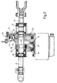
- Number 1 in Fig.1 indicates a steering system for instantaneous steering ratio control, comprising a steering wheel 3; a steering box 4 having a pinion 5 connected angularly integral with steering wheel 3; and a linkage indicated as a whole by 6.
- System 1 also comprises a device 7 interposed between steering wheel 3 and steering box 4, and in turn comprising an epicyclic train 8, and an electric motor 9 for controlling a member of train 8.
- Device 7 provides for enabling continuous variation of the total steering ratio ( ⁇ tot) of system 1.
- total steering ratio is intended to mean the number of turns of steering wheel 3 required for achieving the maximum steering angle of wheels 2 on the vehicle (not shown).
- the total steering ratio comprises a first fixed term ⁇ , normally equal to 3 as defined by steering box 4 and linkage 6; and a second variable term defined by epicyclic train 8.
- ⁇ tot ⁇ (nv/nu) where nv and nu respectively indicate the number of turns of steering wheel 3 and the number of turns of pinion 5 of steering box 4, and ⁇ indicates, as stated, the fixed steering ratio.
- device 7 also comprises a unit 9' for controlling electric motor 9 and in turn comprising a control system 10 for supplying electric motor 9 with a control signal at least in response to a signal supplied by a speed sensor 11 also forming part of device 7 and which provides for detecting the speed of the vehicle and supplying a signal V to control system 10.
- a control system 10 for supplying electric motor 9 with a control signal at least in response to a signal supplied by a speed sensor 11 also forming part of device 7 and which provides for detecting the speed of the vehicle and supplying a signal V to control system 10.
- Device 7 also comprises a number of further sensors connected to control system 10, more specifically, a pair of sensors 12 and 13 for respectively detecting the rotation angle of steering wheel 3 and pinion 5 of steering box 4, and supplying respective signals ⁇ 1 and ⁇ 2; sensor 14 for detecting lateral acceleration ay of the vehicle; sensor 15 for detecting the yaw velocity Vim of the vehicle; and sensor 16 for detecting the speed Wme of electric motor 9.
- System 10 controls the speed of electric motor 9 via an electronic power board 17, which is supplied by system 10 with an enabling signal S1, and two signals S2 and S3 respectively proportional to a reference speed of motor 9 and to the actual speed of motor 9 detected by sensor 16.
- Power board 17 in turn supplies an error signal Se to control system 10, and a control signal S4 to electric motor 9.
- epicyclic train 8 comprises a ring gear 18 connected in angularly-fixed manner to steering wheel 3 by a first shaft 19; and a planet carrier 20 connected angularly integral with pinion 5 of steering box 4 by a second shaft 21.
- epicyclic train 8 and electric motor 9 are housed inside an outer casing 29; and first and second shafts 19 and 21 and output shaft 24 of electric motor 9 are connected to outer casing 29 via respective bearings 30, 31 and 32.
- sensors 11, 14 and 15 respectively detect and communicate to control system 10 the speed, lateral acceleration and yaw velocity of the vehicle.
- sensors 11, 14 and 15 supply respective signals V , ay and Vim to control system 10, which processes the appropriate strategy and enables power board 17, which in turn energizes electric motor 9 so as to rotate sun gear 22.
- Variable rotation of sun gear 22 as a function of vehicle speed results in continuous variation of ratio nv/nu and, consequently, continuous variation of total steering ratio ⁇ tot.
- epicyclic train 8 is so designed that, for very low vehicle speeds, as when maneuvering the vehicle, the total steering ratio rtot assumes a value of approximately 1.
- the speed of electric motor 9 differs according to the speed of the vehicle, and, despite the continuous variation in the total steering ratio and consequently in the torques involved, no corresponding variation in the torque required on steering wheel 3 is discerned by the user.
- the increased torque required on the steering wheel is balanced by the torque exerted on system 1 by electric motor 9, as shown clearly in the following equations.
- Steering system 1 as described above thus provides for a high degree of reliability, by virtue, firstly, of the irreversible connection of sun gear 22 and electric motor 9, which enables motion to be transmitted from motor 9 to sun gear 22, but not vice versa.
- gear train 8 may be replaced by another component, for example, connecting two members of gear train 8.
Landscapes
- Engineering & Computer Science (AREA)
- Chemical & Material Sciences (AREA)
- Combustion & Propulsion (AREA)
- Transportation (AREA)
- Mechanical Engineering (AREA)
- Power Steering Mechanism (AREA)
- Steering Control In Accordance With Driving Conditions (AREA)
Applications Claiming Priority (2)
| Application Number | Priority Date | Filing Date | Title |
|---|---|---|---|
| ITTO911005 | 1991-12-20 | ||
| ITTO911005A IT1250885B (it) | 1991-12-20 | 1991-12-20 | Sistema di sterzatura per il controllo istantaneo del rapporto di sterzo. |
Publications (1)
| Publication Number | Publication Date |
|---|---|
| EP0548854A1 true EP0548854A1 (fr) | 1993-06-30 |
Family
ID=11409809
Family Applications (1)
| Application Number | Title | Priority Date | Filing Date |
|---|---|---|---|
| EP92121622A Withdrawn EP0548854A1 (fr) | 1991-12-20 | 1992-12-18 | Système de direction pour le réglage sans retardement de l'engrenate de direction |
Country Status (3)
| Country | Link |
|---|---|
| EP (1) | EP0548854A1 (fr) |
| JP (1) | JPH0616142A (fr) |
| IT (1) | IT1250885B (fr) |
Cited By (4)
| Publication number | Priority date | Publication date | Assignee | Title |
|---|---|---|---|---|
| WO2003066414A1 (fr) * | 2002-02-06 | 2003-08-14 | Zf Lenksysteme Gmbh | Systeme de direction asservi |
| EP1359083A2 (fr) * | 2002-04-24 | 2003-11-05 | Koyo Seiko Co., Ltd. | Direction pour véhicule |
| EP1415887A2 (fr) * | 2002-10-31 | 2004-05-06 | Bayerische Motoren Werke Aktiengesellschaft | Système de direction actif pour un véhicule à voie multiple |
| US7303045B2 (en) | 2003-03-18 | 2007-12-04 | Jtekt Corporation | Motor vehicle steering device |
Citations (9)
| Publication number | Priority date | Publication date | Assignee | Title |
|---|---|---|---|---|
| US3143006A (en) * | 1962-11-13 | 1964-08-04 | Kratochvil Anton | Gear train |
| US3165943A (en) * | 1959-12-23 | 1965-01-19 | Edward V Sundt | Steering gear mechanism |
| US3831701A (en) * | 1972-12-07 | 1974-08-27 | Ford Motor Co | Power steering gear actuator |
| DE2952087A1 (de) * | 1979-12-22 | 1981-07-02 | Daimler-Benz Ag, 7000 Stuttgart | Lenkungsanordnung fuer kraftfahrzeuge |
| DE3502577A1 (de) * | 1985-01-26 | 1986-07-31 | Audi AG, 8070 Ingolstadt | Lenkung fuer kraftfahrzeuge |
| US4658927A (en) * | 1984-11-19 | 1987-04-21 | Mazda Motor Corporation | Steering system for vehicle |
| FR2622857A1 (fr) * | 1987-11-10 | 1989-05-12 | Renault | Mecanisme de direction a demultiplication variable asservi a la vitesse du vehicule |
| DE3830654A1 (de) * | 1988-09-09 | 1989-11-23 | Daimler Benz Ag | Vorhaltelenkung |
| GB2249530A (en) * | 1990-10-17 | 1992-05-13 | Mitsubishi Motors Corp | Vehicle steering correction control apparatus. |
-
1991
- 1991-12-20 IT ITTO911005A patent/IT1250885B/it active IP Right Grant
-
1992
- 1992-12-18 JP JP4339025A patent/JPH0616142A/ja active Pending
- 1992-12-18 EP EP92121622A patent/EP0548854A1/fr not_active Withdrawn
Patent Citations (9)
| Publication number | Priority date | Publication date | Assignee | Title |
|---|---|---|---|---|
| US3165943A (en) * | 1959-12-23 | 1965-01-19 | Edward V Sundt | Steering gear mechanism |
| US3143006A (en) * | 1962-11-13 | 1964-08-04 | Kratochvil Anton | Gear train |
| US3831701A (en) * | 1972-12-07 | 1974-08-27 | Ford Motor Co | Power steering gear actuator |
| DE2952087A1 (de) * | 1979-12-22 | 1981-07-02 | Daimler-Benz Ag, 7000 Stuttgart | Lenkungsanordnung fuer kraftfahrzeuge |
| US4658927A (en) * | 1984-11-19 | 1987-04-21 | Mazda Motor Corporation | Steering system for vehicle |
| DE3502577A1 (de) * | 1985-01-26 | 1986-07-31 | Audi AG, 8070 Ingolstadt | Lenkung fuer kraftfahrzeuge |
| FR2622857A1 (fr) * | 1987-11-10 | 1989-05-12 | Renault | Mecanisme de direction a demultiplication variable asservi a la vitesse du vehicule |
| DE3830654A1 (de) * | 1988-09-09 | 1989-11-23 | Daimler Benz Ag | Vorhaltelenkung |
| GB2249530A (en) * | 1990-10-17 | 1992-05-13 | Mitsubishi Motors Corp | Vehicle steering correction control apparatus. |
Cited By (7)
| Publication number | Priority date | Publication date | Assignee | Title |
|---|---|---|---|---|
| WO2003066414A1 (fr) * | 2002-02-06 | 2003-08-14 | Zf Lenksysteme Gmbh | Systeme de direction asservi |
| EP1359083A2 (fr) * | 2002-04-24 | 2003-11-05 | Koyo Seiko Co., Ltd. | Direction pour véhicule |
| EP1359083A3 (fr) * | 2002-04-24 | 2005-06-22 | Koyo Seiko Co., Ltd. | Direction pour véhicule |
| EP1415887A2 (fr) * | 2002-10-31 | 2004-05-06 | Bayerische Motoren Werke Aktiengesellschaft | Système de direction actif pour un véhicule à voie multiple |
| EP1415887A3 (fr) * | 2002-10-31 | 2004-10-20 | Bayerische Motoren Werke Aktiengesellschaft | Système de direction actif pour un véhicule à voie multiple |
| US7303045B2 (en) | 2003-03-18 | 2007-12-04 | Jtekt Corporation | Motor vehicle steering device |
| EP1459959B2 (fr) † | 2003-03-18 | 2010-03-17 | Jtekt Corporation | Direction de véhicule automobile |
Also Published As
| Publication number | Publication date |
|---|---|
| ITTO911005A1 (it) | 1993-06-20 |
| ITTO911005A0 (it) | 1991-12-20 |
| JPH0616142A (ja) | 1994-01-25 |
| IT1250885B (it) | 1995-04-21 |
Similar Documents
| Publication | Publication Date | Title |
|---|---|---|
| EP0189172B1 (fr) | Système de direction pour véhicule automobile ou équivalent | |
| EP0247820B1 (fr) | Transmission différentielle | |
| KR102657328B1 (ko) | 스티어 바이 와이어 시스템용 조향장치 | |
| US6763907B2 (en) | Vehicle steering apparatus | |
| EP1561972B1 (fr) | Transmission | |
| US20080073143A1 (en) | Steering device for vehicle | |
| GB2332026A (en) | Coupling device with starting and cornering assistance control | |
| GB2205541A (en) | Power steering system | |
| US4715462A (en) | Electric power assistance steering system | |
| CA1279268C (fr) | Systeme de servodirection pour vehicules automobiles | |
| EP0248582B1 (fr) | Transmission différentielle | |
| EP0548854A1 (fr) | Système de direction pour le réglage sans retardement de l'engrenate de direction | |
| CN111615482B (zh) | 用于使可操纵的车轮转向的装置 | |
| US6138787A (en) | Motor-driven system for steering a vehicle | |
| JPS6410385B2 (fr) | ||
| JPH029986B2 (fr) | ||
| US4652002A (en) | Steering system for a motor vehicle | |
| EP3409563A1 (fr) | Agencement d'entraînement dans un véhicule | |
| JP2824493B2 (ja) | 動力舵取装置 | |
| EP1238889B1 (fr) | Direction à rapport variable | |
| JPH04310475A (ja) | 電動式動力舵取装置 | |
| JPS61122072A (ja) | 自動車のステアリング装置 | |
| JPH0442182Y2 (fr) | ||
| JPH0410106Y2 (fr) | ||
| JP2982831B2 (ja) | ステアリング舵角補正装置 |
Legal Events
| Date | Code | Title | Description |
|---|---|---|---|
| PUAI | Public reference made under article 153(3) epc to a published international application that has entered the european phase |
Free format text: ORIGINAL CODE: 0009012 |
|
| AK | Designated contracting states |
Kind code of ref document: A1 Designated state(s): DE ES FR GB IT SE |
|
| RAP1 | Party data changed (applicant data changed or rights of an application transferred) |
Owner name: CENTRO RICERCHE FIAT SOCIETA CONSORTILE PER AZIONI |
|
| STAA | Information on the status of an ep patent application or granted ep patent |
Free format text: STATUS: THE APPLICATION IS DEEMED TO BE WITHDRAWN |
|
| 18D | Application deemed to be withdrawn |
Effective date: 19931231 |