EP0248191A2 - Vorrichtung zum Aufhängen von Fahrleitungen an Tragseilen - Google Patents
Vorrichtung zum Aufhängen von Fahrleitungen an Tragseilen Download PDFInfo
- Publication number
- EP0248191A2 EP0248191A2 EP87105914A EP87105914A EP0248191A2 EP 0248191 A2 EP0248191 A2 EP 0248191A2 EP 87105914 A EP87105914 A EP 87105914A EP 87105914 A EP87105914 A EP 87105914A EP 0248191 A2 EP0248191 A2 EP 0248191A2
- Authority
- EP
- European Patent Office
- Prior art keywords
- fact
- suspension
- shaped
- elements
- legs
- Prior art date
- Legal status (The legal status is an assumption and is not a legal conclusion. Google has not performed a legal analysis and makes no representation as to the accuracy of the status listed.)
- Granted
Links
Images

Classifications
-
- B—PERFORMING OPERATIONS; TRANSPORTING
- B60—VEHICLES IN GENERAL
- B60M—POWER SUPPLY LINES, AND DEVICES ALONG RAILS, FOR ELECTRICALLY- PROPELLED VEHICLES
- B60M1/00—Power supply lines for contact with collector on vehicle
- B60M1/12—Trolley lines; Accessories therefor
- B60M1/20—Arrangements for supporting or suspending trolley wires, e.g. from buildings
- B60M1/23—Arrangements for suspending trolley wires from catenary line
Definitions
- This invention refers to a device for suspending electric trolley wires to messenger cables, in particular for suspending trolley wires in lines for the electrification of railways and the like.
- the trolley wire In carrying out electric trolley wires for railways and the like, the trolley wire usually runs parallel to the rails, since it is suspended from a messenger or supporting cable by means of stay wires or other suitable suspension devices.
- the messenger cable is arched between two adjacent anchorage points; consequently, the distance between the messenger cable and the electric wire varies from point to point, ranging from a maximum in correspondence with the anchorage points of the cable to a minimum at the centre.
- suspension devices of different lengths or which can be adapted or adjusted on the site in order to suit the various requirements.
- the suspension device must in general permit the isolation of the supporting cable from the overhead electric line and, in the case of electric contact lines for railways, allow a certain amount of upward movement of the electric wire in order to compensate for the thrust exerted by the trolley, without the tensile stress on the electric wire undergoing sudden variations.
- suspension devices of various types and shapes, that is to say, of fixed length or which can be adjusted for example by means of stay bolts, or having a particular shape; however, to date, no-one has yet put forward a solution to the problem of suspending an electric wire and of adjusting the length of the suspension device which, in addition to ensuring the required characteristics of electrical insulation and mechanical strength under widely varied environmental conditions, is also easy and cheap to produce with reinforced plastic materials, and which at the same time is also easy to use and to adjust at the site.
- the suspension elements of the electric conductor can be made in different ways; for example, they can be made up of two opposing U-shaped elements having toothed legs place near each other and held by a securing clamp so as to form a closed loop that can be lengthened or shortened as required by sliding one toothed element lengthwise with respect to the other, or they can be in the form of a toothed bar one end of which is connected to a hanging clamp of the electric wire or of the supporting cable.
- an electric wire lO of an electrification line for railways and the like is suspended from a messenger cable by means of a plurality of supporting devices l2 which are pivoted or connected to hanging clamps l3 and l4 designed to secure themselves to the electric conductor or wire lO and to the messenger cable ll, as shown.
- the suspension device l2 must be able to adapt its length to the variable distance between conductor lO and messenger cable ll; it must consequently be adjustable in length in order to enable it to be assembled and adjusted at the site with the utmost ease, and to adapt to any situation.
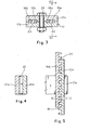
- the supporting device l2 in the example shown, is made up of two toothed elements l5 and l6 which are elongated in the direction of their longitudinal axes and provided on at least one face with a plurality of crosswise teeth aligned in the direction of the longitudinal axis of each individual element.
- One or more intermediate clamps l7 serve the purpose of connecting or keeping the two toothed elements l5, l6 engaged with each other in a coplanar or overlapped condition according to the lateral or frontal disposition of the teeth.
- the two elements l5 and l6 are identical and each consist of a U-shaped element, with legs l5a, l5b and respectively l6a, l6b, provided on one side with teeth l9 and 2O.
- each leg is provided with only one row of teeth
- the teeth of both legs l5a, l5b and l6a, l6b of each element are disposed on the same side of the legs.
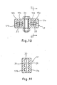
- the two U-shaped toothed elements are positioned in the same plane, one next to the other, with the corresponding toothed legs l5a, l6a and l5b, l6b opposite each other and with their teeth reciprocally engaged over at least part of the length of the legs, passing through grooves 22 and 23 in the securing clamp l7.
- the clamp l7 is preferably made up of two matching halves l7a and l7b which are disengageably secured together by means of one or more bolts 24.
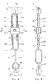
- the device l2 is completed by a movable link member 25 connecting it to one of the hanging clamps, for example to clamp l3 connected to the electric conductor lO, so as to allow the conductor lO a certain amount of lateral and relative upwards movements, which are necessary in order to to compensate for the thrust exerted by the pantograph trolley or by the current collector which runs along the conductor wire lO whenever a train passes.
- the link member 25 consists of a double eyelet element having a first circular eyelet 26 which connects with the clamp l3 and a second elongated eyelet 27 lying in a plane at right angles to that of the eyelet 26 which connects with the previously described suspension device l2.
- the suspension device according to this invention is used as follows: the two opposing U-shaped elements are placed close together in the same plane to form a loop, with their teeth engaged after having passed the toothed element l5 through the elongated eyelet 27 of the lower link member 25; then the relative position of the two U-shaped elements is adjusted according to the desired length of the suspension device, and the clamp l7 is fitted onto them and tightened with its bolt 24. After having assembled the device, the two end clamps l3 and l4 are fitted on and then secured respectively to the conductor lO and the cable ll.
- the entire suspension device preferably the two toothed elements l5, l6 and the lower link member 25, are advantageously made of fibreglass reinforced plastic material, for example of compact polycarbonate with a fibreglass filler, so as to give the whole assembly a highly resistant rigid structure which electrically isolates the cable ll from the electric conductor lO.
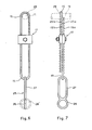
- FIGS 6 and 7 of the drawings show a second embodiment.
- both of the U-shaped toothed elements l5 and l6 are provided with toothing l9a, l9b and 2Oa, 2Ob on both main faces, as shown; in particular, the teeth on one of the faces of each element l5, l6 can be aligned with the teeth on the other face, or can be shifted in a longitudinal direction by half a pitch, that is to say, by half the distance between one tooth and the next, in order to enable the device to be adjusted in length more easily.
- the device of figures 6 and 7 can be made in exactly the same way as the previous example, however, as shown, in certain cases the upper clamp l4 can be eliminated due to the fact that the upper U-shaped element l6 can be provided with a saddle and placed directly astride the suspension cable ll.
- the lower element 25 is modified in such a way that both the eyelets 26 and 27 are coplanar instead of at right angles to each other, as shown by the dotted line 26 ⁇ in the same figure and in the previous ones.
- the remainder of the device of figures 6 and 7 is made up and used in a wholly identical way to the previous one; consequently, the same numerical references have been used to indicate similar or functionally equivalent parts.
- a third embodiment is shown in the figures from 8 to ll of the accompanying drawings.
- the supporting device l2 is likewise made up of two toothed elements l5 and l6 sliding in the direction of their longitudinal axis and provided on at least one of the front and/or rear faces with a plurality of crosswise teeth l9, 2O, disposed aligned in the direction of the longitudinal axis of each individual element.
- One or more intermediate clamps l7 serve as before to connect the two suspension elements together in the coplanar condition of the elements l5 and l6 and positioned as shown in figures 8 and 9.
- the two elements l5 and l6 are identical, of equal length and each consisting of an U-shaped element, with legs l5a, l5b and respectively l6a, provided with teeth l9 and 2O on both of the front and rear faces.
- the two U-shaped toothed elements are disposed side by side in the same plane, as in the first case, with the corresponding toothed legs in contact, and with the teeth aligned with one another so as to permit their engagement with an identical double toothing 2l provided on opposing sides of two through slots 22 and 23 in the securing clamp l7.
- the clamp l7 is preferably made up of two matching halves l7a and l7b which are disengageably secured together by means of one or more bolts 24.
- the device l2 is completed by a link member 25 to connect it to the lower clamp l3 of the electric conductor, in such a way as to permit lateral movement and relative upward movement, as in the previous cases.
- the same numerical references have also been used in this latter case to indicate similar or functionally equivalent parts.
Landscapes
- Engineering & Computer Science (AREA)
- Mechanical Engineering (AREA)
- Clamps And Clips (AREA)
- Suspension Of Electric Lines Or Cables (AREA)
Applications Claiming Priority (2)
| Application Number | Priority Date | Filing Date | Title |
|---|---|---|---|
| IT2171686U | 1986-05-02 | ||
| IT2171686U IT209084Z2 (it) | 1986-05-02 | 1986-05-02 | Dispositivo per la sospensione di linee elettriche a funi portanti. |
Publications (3)
| Publication Number | Publication Date |
|---|---|
| EP0248191A2 true EP0248191A2 (de) | 1987-12-09 |
| EP0248191A3 EP0248191A3 (en) | 1989-06-14 |
| EP0248191B1 EP0248191B1 (de) | 1992-04-08 |
Family
ID=11185851
Family Applications (1)
| Application Number | Title | Priority Date | Filing Date |
|---|---|---|---|
| EP19870105914 Expired EP0248191B1 (de) | 1986-05-02 | 1987-04-22 | Vorrichtung zum Aufhängen von Fahrleitungen an Tragseilen |
Country Status (3)
| Country | Link |
|---|---|
| EP (1) | EP0248191B1 (de) |
| DE (1) | DE3778064D1 (de) |
| IT (1) | IT209084Z2 (de) |
Cited By (4)
| Publication number | Priority date | Publication date | Assignee | Title |
|---|---|---|---|---|
| GB2209440A (en) * | 1987-08-20 | 1989-05-10 | Burndy Corp | Clamp for connecting to electric cable |
| FR2811945A1 (fr) * | 2000-07-24 | 2002-01-25 | Gen Hydraulique Mecanique Soc | Dispositif de fixation d'une console de catenaire sur un mat |
| AT410197B (de) * | 2000-05-10 | 2003-02-25 | Roehl Hans Heinrich Ing | Hängeklemme |
| JP2016150666A (ja) * | 2015-02-18 | 2016-08-22 | 東日本旅客鉄道株式会社 | トロリ線吊り位置調整装置及び方法 |
Family Cites Families (1)
| Publication number | Priority date | Publication date | Assignee | Title |
|---|---|---|---|---|
| US1643749A (en) * | 1927-03-16 | 1927-09-27 | Louden Machinery Co | Hanger for overhead trackways |
-
1986
- 1986-05-02 IT IT2171686U patent/IT209084Z2/it active
-
1987
- 1987-04-22 DE DE87105914T patent/DE3778064D1/de not_active Expired - Fee Related
- 1987-04-22 EP EP19870105914 patent/EP0248191B1/de not_active Expired
Cited By (5)
| Publication number | Priority date | Publication date | Assignee | Title |
|---|---|---|---|---|
| GB2209440A (en) * | 1987-08-20 | 1989-05-10 | Burndy Corp | Clamp for connecting to electric cable |
| GB2209440B (en) * | 1987-08-20 | 1991-09-04 | Burndy Corp | Modular adjustable clamp system |
| AT410197B (de) * | 2000-05-10 | 2003-02-25 | Roehl Hans Heinrich Ing | Hängeklemme |
| FR2811945A1 (fr) * | 2000-07-24 | 2002-01-25 | Gen Hydraulique Mecanique Soc | Dispositif de fixation d'une console de catenaire sur un mat |
| JP2016150666A (ja) * | 2015-02-18 | 2016-08-22 | 東日本旅客鉄道株式会社 | トロリ線吊り位置調整装置及び方法 |
Also Published As
| Publication number | Publication date |
|---|---|
| IT209084Z2 (it) | 1988-09-06 |
| DE3778064D1 (en) | 1992-05-14 |
| EP0248191A3 (en) | 1989-06-14 |
| EP0248191B1 (de) | 1992-04-08 |
| IT8621716V0 (it) | 1986-05-02 |
Similar Documents
| Publication | Publication Date | Title |
|---|---|---|
| MY102835A (en) | Wiring harness | |
| EP0248191A2 (de) | Vorrichtung zum Aufhängen von Fahrleitungen an Tragseilen | |
| CA2046479A1 (en) | Cross-type clamp and connection produced thereby between two crossed wire cables, and wire cable net with cross-type clamps | |
| US4363939A (en) | Electrical supply line for the supply or current to railway vehicles | |
| DE759730C (de) | Fahrdrahtaufhaengung | |
| HUP0303033A2 (en) | Pole top support for aerial electric power lines | |
| RU168353U1 (ru) | Анкерный кронштейн | |
| JPS6338687Y2 (de) | ||
| JPS591390Y2 (ja) | 架空送電線の横振れ防止型ジヤンパ装置 | |
| EP0044625A1 (de) | Aufhängung des Lambda-Typs für einen Oberleitungs-Fahrdraht | |
| JP4067459B2 (ja) | 剛体電車線の終端装置 | |
| EP4134270A1 (de) | Verbindungsanordnung zwischen oberleitungen einer oberleitungsanlage | |
| JPH038024Y2 (de) | ||
| DE1951159U (de) | Haenger fuer fahrleitungen elektrischer bahnen. | |
| JPS6029781Y2 (ja) | 電柱用中線引留金具 | |
| RU175739U1 (ru) | Натяжной зажим | |
| RU121966U1 (ru) | Натяжной зажим для изолированного воздушного кабеля | |
| RU172598U1 (ru) | Натяжной зажим | |
| FR2379922A1 (fr) | Dispositif pour regler la longueur de cables divers | |
| SU1242408A1 (ru) | Воздушна стрелка железнодорожной контактной сети | |
| DE164565C (de) | ||
| JPH0640422Y2 (ja) | 吊架式ジャンパ装置 | |
| DE322486C (de) | Fahrleitung fuer elektrische Bahnen mit uebereinander angeordneten Fahrdraehten | |
| SU553703A1 (ru) | Устройство дл подвески проводов на опорах с траверсами низковольтной мнонопроводной воздушной линии | |
| JP3682812B2 (ja) | 剛体電車線 |
Legal Events
| Date | Code | Title | Description |
|---|---|---|---|
| PUAI | Public reference made under article 153(3) epc to a published international application that has entered the european phase |
Free format text: ORIGINAL CODE: 0009012 |
|
| AK | Designated contracting states |
Kind code of ref document: A2 Designated state(s): CH DE ES FR GB LI NL SE |
|
| PUAL | Search report despatched |
Free format text: ORIGINAL CODE: 0009013 |
|
| AK | Designated contracting states |
Kind code of ref document: A3 Designated state(s): CH DE ES FR GB LI NL SE |
|
| 17P | Request for examination filed |
Effective date: 19890918 |
|
| 17Q | First examination report despatched |
Effective date: 19910313 |
|
| GRAA | (expected) grant |
Free format text: ORIGINAL CODE: 0009210 |
|
| AK | Designated contracting states |
Kind code of ref document: B1 Designated state(s): CH DE ES FR GB LI NL SE |
|
| PG25 | Lapsed in a contracting state [announced via postgrant information from national office to epo] |
Ref country code: SE Effective date: 19920408 Ref country code: NL Effective date: 19920408 Ref country code: LI Effective date: 19920408 Ref country code: CH Effective date: 19920408 |
|
| REF | Corresponds to: |
Ref document number: 3778064 Country of ref document: DE Date of ref document: 19920514 |
|
| REG | Reference to a national code |
Ref country code: CH Ref legal event code: PL |
|
| PG25 | Lapsed in a contracting state [announced via postgrant information from national office to epo] |
Ref country code: ES Free format text: LAPSE BECAUSE OF FAILURE TO SUBMIT A TRANSLATION OF THE DESCRIPTION OR TO PAY THE FEE WITHIN THE PRESCRIBED TIME-LIMIT Effective date: 19920719 |
|
| ET | Fr: translation filed | ||
| NLV1 | Nl: lapsed or annulled due to failure to fulfill the requirements of art. 29p and 29m of the patents act | ||
| PLBE | No opposition filed within time limit |
Free format text: ORIGINAL CODE: 0009261 |
|
| STAA | Information on the status of an ep patent application or granted ep patent |
Free format text: STATUS: NO OPPOSITION FILED WITHIN TIME LIMIT |
|
| 26N | No opposition filed | ||
| PGFP | Annual fee paid to national office [announced via postgrant information from national office to epo] |
Ref country code: GB Payment date: 19930415 Year of fee payment: 7 |
|
| PGFP | Annual fee paid to national office [announced via postgrant information from national office to epo] |
Ref country code: FR Payment date: 19930421 Year of fee payment: 7 |
|
| PGFP | Annual fee paid to national office [announced via postgrant information from national office to epo] |
Ref country code: DE Payment date: 19930630 Year of fee payment: 7 |
|
| PG25 | Lapsed in a contracting state [announced via postgrant information from national office to epo] |
Ref country code: GB Effective date: 19940422 |
|
| GBPC | Gb: european patent ceased through non-payment of renewal fee |
Effective date: 19940422 |
|
| PG25 | Lapsed in a contracting state [announced via postgrant information from national office to epo] |
Ref country code: FR Effective date: 19941229 |
|
| PG25 | Lapsed in a contracting state [announced via postgrant information from national office to epo] |
Ref country code: DE Effective date: 19950103 |
|
| REG | Reference to a national code |
Ref country code: FR Ref legal event code: ST |