EP0247527B1 - Hydroponisches Anbausystem - Google Patents
Hydroponisches Anbausystem Download PDFInfo
- Publication number
- EP0247527B1 EP0247527B1 EP87107422A EP87107422A EP0247527B1 EP 0247527 B1 EP0247527 B1 EP 0247527B1 EP 87107422 A EP87107422 A EP 87107422A EP 87107422 A EP87107422 A EP 87107422A EP 0247527 B1 EP0247527 B1 EP 0247527B1
- Authority
- EP
- European Patent Office
- Prior art keywords
- carbon dioxide
- plant cultivation
- cultivation room
- panel structure
- air
- Prior art date
- Legal status (The legal status is an assumption and is not a legal conclusion. Google has not performed a legal analysis and makes no representation as to the accuracy of the status listed.)
- Expired - Lifetime
Links
Images


Classifications
-
- A—HUMAN NECESSITIES
- A01—AGRICULTURE; FORESTRY; ANIMAL HUSBANDRY; HUNTING; TRAPPING; FISHING
- A01G—HORTICULTURE; CULTIVATION OF VEGETABLES, FLOWERS, RICE, FRUIT, VINES, HOPS OR SEAWEED; FORESTRY; WATERING
- A01G9/00—Cultivation in receptacles, forcing-frames or greenhouses; Edging for beds, lawn or the like
- A01G9/24—Devices or systems for heating, ventilating, regulating temperature, illuminating, or watering, in greenhouses, forcing-frames, or the like
- A01G9/247—Watering arrangements
-
- A—HUMAN NECESSITIES
- A01—AGRICULTURE; FORESTRY; ANIMAL HUSBANDRY; HUNTING; TRAPPING; FISHING
- A01G—HORTICULTURE; CULTIVATION OF VEGETABLES, FLOWERS, RICE, FRUIT, VINES, HOPS OR SEAWEED; FORESTRY; WATERING
- A01G31/00—Soilless cultivation, e.g. hydroponics
- A01G31/02—Special apparatus therefor
- A01G31/06—Hydroponic culture on racks or in stacked containers
-
- A—HUMAN NECESSITIES
- A01—AGRICULTURE; FORESTRY; ANIMAL HUSBANDRY; HUNTING; TRAPPING; FISHING
- A01G—HORTICULTURE; CULTIVATION OF VEGETABLES, FLOWERS, RICE, FRUIT, VINES, HOPS OR SEAWEED; FORESTRY; WATERING
- A01G31/00—Soilless cultivation, e.g. hydroponics
- A01G31/02—Special apparatus therefor
- A01G31/065—Special apparatus therefor with means for recycling the nutritive solution
-
- Y—GENERAL TAGGING OF NEW TECHNOLOGICAL DEVELOPMENTS; GENERAL TAGGING OF CROSS-SECTIONAL TECHNOLOGIES SPANNING OVER SEVERAL SECTIONS OF THE IPC; TECHNICAL SUBJECTS COVERED BY FORMER USPC CROSS-REFERENCE ART COLLECTIONS [XRACs] AND DIGESTS
- Y02—TECHNOLOGIES OR APPLICATIONS FOR MITIGATION OR ADAPTATION AGAINST CLIMATE CHANGE
- Y02A—TECHNOLOGIES FOR ADAPTATION TO CLIMATE CHANGE
- Y02A40/00—Adaptation technologies in agriculture, forestry, livestock or agroalimentary production
- Y02A40/10—Adaptation technologies in agriculture, forestry, livestock or agroalimentary production in agriculture
- Y02A40/25—Greenhouse technology, e.g. cooling systems therefor
-
- Y—GENERAL TAGGING OF NEW TECHNOLOGICAL DEVELOPMENTS; GENERAL TAGGING OF CROSS-SECTIONAL TECHNOLOGIES SPANNING OVER SEVERAL SECTIONS OF THE IPC; TECHNICAL SUBJECTS COVERED BY FORMER USPC CROSS-REFERENCE ART COLLECTIONS [XRACs] AND DIGESTS
- Y02—TECHNOLOGIES OR APPLICATIONS FOR MITIGATION OR ADAPTATION AGAINST CLIMATE CHANGE
- Y02P—CLIMATE CHANGE MITIGATION TECHNOLOGIES IN THE PRODUCTION OR PROCESSING OF GOODS
- Y02P60/00—Technologies relating to agriculture, livestock or agroalimentary industries
- Y02P60/20—Reduction of greenhouse gas [GHG] emissions in agriculture, e.g. CO2
- Y02P60/21—Dinitrogen oxide [N2O], e.g. using aquaponics, hydroponics or efficiency measures
Definitions
- This invention relates to a hydroponic culture system which provides systematic, economical, and efficient hydroponic culture for almost uniform plants.
- a prior art hydroponic culture system which includes the features set forth in the first part of claims 1, 3 and 6, has been disclosed in GB-A-1 443 326.
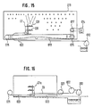
- plants are supported on a roof-shaped panel structure 01 having a number of holes, supplied with sunshine through a transparent arch roof 02, and with a hydroponic solution sprayed onto the roots of the plants from a hydroponic solution spraying mechanism 03 as shown in Fig. 14, to cultivate the plants.
- the hydroponic solution spraying mechanism 03 is fixed inside the panel structure 01 and is provided with a number of spray nozzles disposed along the longitudinal direction of the panel structure 01 to spray the hydroponic solution onto the roots of the plants.
- the hydroponic culture system shown in the application has a hydroponic solution spraying mechanism 07 and a hydroponic solution pumping mechanism consisting of a flexible hose 020 and a hydroponic solution pump 012.
- the hydroponic solution spraying mechanism 07 which is provided with four spray nozzles 031, is located inside a roof-shaped panel structure 011 and movable in the longitudinal direction thereof.
- the endless drive chain 013 is wound at its ends around rolls 015 which are driven to rotate by a motor 014 through a roll 017.
- the hydroponic solution spraying mechanism 07 is mounted on the endless drive chain 013 which is driven by the motor 014 to move the hydroponic solution spraying mechanism 07 along the longitudinal direction of the panel structure 011.
- the hydroponic solution spraying mechanism 07 is connected to the hydroponic solution pump 012 through the flexible hose 020 and, as shown in Fig. 16, a hose winding unit 022 is provided to prevent the flexible hose 020 from being slack.
- a hydroponic solution spraying mechanism 07a is reciprocally moved by reversibly winding a rope 023 of which front and rear ends are fixed to rope winding units 021.
- hydroponic culture system which can uniformly spray the roots of plants supported by angle panels with the hydroponic solution or the like and easily move the hydroponic solution spraying mechanism by a compact means, thereby enabling systematic and uniform cultivation of the plants with improved economy.
- Fig.1, Fig.2 and Fig.3 are schematic views showing a first embodiment of the hydroponic culture system according to the present invention.
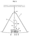
- Fig.4 and Fig.5 are a front view and a side view, respectively, of a hydroponic solution spraying mechanism of the first embodiment according to the present invention.
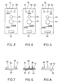
- Fig.6 and Fig.7 are a front view and a side view, respectively, of a position detecting means of the first embodiment according to the present invention.
- Fig.8 and Fig.9 are schematic views showing a test example in the first embodiment according to the present invention.
- Fig.10 through Fig.12 are schematic views showing an environment control means for a plant cultivation room of a second embodiment according to the present invention.
- Fig.13 and Fig.14 are schematic views showing prior art hydroponic culture systems.
- Fig.15 and Fig.16 are front views showing a hydroponic solution spraying mechanism of a hydroponic culture system according to the previous application.
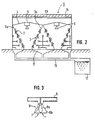
- Fig.1 and Fig.2 are schematic views showing the first embodiment of the hydroponic culture system according to the present invention.
- roof-shaped panel structures 3 disposed in a plurality of rows in a plant cultivation room 1.
- Each of these roof-shaped panel structures which in the following are referred to as "angle panels”, consists of two panels 3a with top edges joined, having a number of holes to support plants with roots projected inside the angle panels, and both ends of the rows of the angle panels are connected to side walls 1a.
- Top edges of the adjacent angle panels 3 are connected with canopies 4 having an angular cross-section to prevent diffusion of light to the upper side, forming nearly triangular-sectioned spaces surrounded by the adjacent angle panels 3 and the canopies 4.
- the exhaust ducts 5 as an exhaust means are provided at the center of the canopies 4, and lighting apparatus 6 are disposed under the exhaust ducts 5, which are arranged with nearly equal spacings along the longitudinal direction of the angle panels 3.
- the angle panels 3 can be made of foamed polystyrene, stainless steel, reinforced plastics, or ceramics, and have an inclination angle of 40 to 70 degrees, preferably 60 degrees, from the horizontal plane in view of the cultivation and lighting efficiencies.
- the canopies 4 can also have another cross-section, other than the angular cross-section, such as an arc cross-section that may provide concentration of heat to a limited position under the canopies and improved exhaust efficiency, and preferably be made of a heat-insulating material such as foamed polystyrene, or the heat-insulated material bonded with a reflecting material such as stainless steel plate or aluminum foil.
- the lighting apparatus 6 consists of a lamp 6a such as a sodium lamp or mercury lamp and a cover 6b, and an exhaust port 7 communicating with the exhaust duct 5 is formed between the lamp 6a and the cover 6b.
- the cover 6b is to prevent diffusion of the radiation heat of the lamp 6a, and can be made of a transparent material.
- the exhaust duct 5 communicates with a duct 8 outside the plant cultivation room 1, and heat in the cultivation space is exhausted by a ventilation fan 9 disposed in the duct 8.
- the side wall 1a of the plant cultivation room 1 is provided with an air supply port 10.
- the air supply port 10 is to introduce the outside air, and can also be connected to an air-conditioning unit to supply cold air to the cultivation space or carbon dioxide when such is in short supply.
- the duct 8 and the air supply port 10 can also be connected to the same air-conditioning unit to recirculate the air. In this case, it is sufficient to replenish the amount of carbon dioxide absorbed by the plant 2, thus providing improved economy.
- the side wall 1a is provided with the air supply port 10, both ends of the rows of the angle panels 3 can be opened instead.
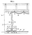
- a hydroponic solution feeding mechanism of this embodiment will be described with reference to Fig.4 through Fig.7.
- rails 112 are disposed on the floor inside the angle panels 3, along the longitudinal direction of the angle panels 3, and a hydroponic solution spraying mechanism 11 with a self-propelling means is disposed on the rails 112.
- the hydroponic solution spraying mechanism 11 consists of a base plate 114 with wheels 113 placed on the rails 112, a stand 115 provided on the base plate 114, and spray nozzles 116 attached on both sides to the stand 115.
- the base plate 114 also has a variable-speed, reversible drive motor 117.
- a sprocket 118 is mounted on the rotary shaft of the drive motor 117, and the upper surface of the sprocket 118 is in engagement with a chain 119 which is disposed along the longitudinal direction of the angle panels 3, thus providing the self-propelling means.
- the chain 119 with both ends fixed, can be lifted up only at the part engaging with the sprocket 118.
- Auxiliary sprockets 120 are disposed at the front and rear sides of the sprocket 118 to prevent excessive lifting of the chain 119.
- a hanger rail 121 is provided at the top of the angle panels 3, along the longitudinal direction of the angle panels 3.
- the hanger rail 121 has, hung thereon, a flexible hose 123 and a power cord 124, through hanger rolls 122.
- One end of the flexible hose 123 is connected to spray nozzles 116 through the stand 115, and the power cord 124 is connected to the drive motor 117.
- the other end of the flexible hose 123 is connected to a hydroponic solution feeding pump, which is not shown, so that the hydroponic solution is fed to the spray nozzles 116 through the hose 123.
- the flexible hose 123 and the pump form a hydroponic solution pumping mechanism.
- the other end of the power cord 124 is connected to a power supply, which is not shown, and the movement of the hydroponic solution spraying mechanism 11 is controlled by signals from position detecting means provided at both ends of the rail 112.
- there are provided proximity switches 125 which sense metals at both ends of the rails 112, and a proximity switch striker 126 made of a metal at the side of the base plate 114.
- the phase of the alternating current supplied to the drive motor 117 is switched to reverse the rotation of the drive motor 117, thereby reciprocally moving the hydroponic solution spraying mechanism 11.
- the proximity switches 125 used in this embodiment are resistant to water and therefore preferably for use as the position detecting means which, however, is in no way limited to such proximity switches; other types may be used such as limit switches or photoelectric tubes.
- the hydroponic solution sprayed and accumulated on the floor is collected through a collection passage 13.
- the inner surface of a ceiling 1b of the plant cultivation room 1 is provided with a heat-insulating material 14.
- the surface of the angle panels 3 can also be provided with a reflective surface in addition to the lower surface of the canopy 4 for further improved lighting efficiency.
- the hydroponic culture system of this embodiment is used as follows.
- Young plants 2 are inserted into a number of holes provided in the angles panels 3.
- Preferred plant types to be cultivated include green vegetables such as lettuce, Brassica Rapa var. pervidis, chrysanthemum coronarium, and spinach.
- the plants are irradiated with light from the lighting apparatus 6, and supplied with the hydroponic solution by the hydroponic solution feeding mechanism. This causes the young plants 2 to grow while absorbing carbon dioxide and oxygen in the plant cultivation room 1.
- an environment control means for controlling the temperature, humidity and carbon dioxide concentration in the plant cultivation room 1, thereby replenishing shortage of carbon dioxide.
- the carbon dioxide can be supplied during the lighting period in which the artificial light is applied to activate the photosynthesis.
- the drive motor 117 is energized to rotate the sprocket 118, which engages with the chain 119 to move the base plate 114 along the rails 112.
- the drive motor 117 is rotated in reverse to move the base plate 114 reciprocally.
- the hydroponic solution is sprayed from the spray nozzles 116 evenly over the roots of the plants.
- the flexible hose 123 and the power cord 124 are automatically expanded and contracted according to the movement of the base plate 114 by the function of the hanger roll 122, thus preventing obstruction to the reciprocal movement of the base plate 114.
- the self-propelling means in the first embodiment consists of the drive motor 117, the sprocket 118, and the chain 119. Since the chain 119 is disposed only one on the floor, there is no difficulty in adjusting the tension of the chain 119, and since there are also provided the auxiliary sprockets 150, the chain 119 and the sprocket 118 will not disengage.
- the self-propelling means is in no way limited to the type as described above; any types may be used that positively move the hydroponic solution spraying mechanism in reciprocal movement.
- a closed-type lighting and an open-type lighting in the first embodiment are compared.
- the closed-type lighting indicates one which uses the hydroponic culture system having the canopies in this embodiment.
- Test systems used are shown in Fig.8 and Fig.9, of which the components are indicated with the same numerals as used in the above-described embodiment with the description omitted.
- the lower surfaces of the canopy 4 in Fig.8 and the ceiling in Fig.9 are provided with reflective surfaces.
- a 940W reflector-type high-pressure sodium lamp with a total light flux of 110,000 lumina is used for the lighting apparatus 6.
- the cultivation conditions include a daytime of 18 hours, a day temperature of 24 degrees C, a night temperature of 18 degrees C, and a carbon dioxide concentration of 1,500 ppm. Young plants of lettuce of 20 days after seeding (with 4 to 5 leaves, about 10 g weight) are planted at positions A to K, and the weights of the individual plants are compared after a cultivation period of 10 days. The result is shown in the Table below.
- the closed-type lighting provides a higher illuminance on the panel surface than the open-type lighting, and a higher growth rate, resulting in a greater plant weight.
- the canopies 4 with exhaust ports 7, as used in the first embodiment, form narrow triangular-sectioned spaces, which provide improved lighting efficiency and reduced load to the air-conditioning unit resulting in considerably reduced power cost, thereby systematically and efficiently producing almost uniform-size plants with improve economy.
- the accumulated heat can be eliminated before the radiation heat diffuses, thereby further reducing the load to the air-conditioning unit.
- a second embodiment according to the present invention will be described with reference to Fig.10 through Fig.12.
- a preferred environment control means for the hydroponic culture system is described.
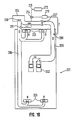
- Fig.10 is a schematic view of an environment control means for this embodiment of the plant cultivation room.
- a plant cultivation room 201 has an exhaust port 202 and an air supply port 203, which are connected to an air-conditioning unit 204 disposed outside through an exhaust duct 205 and an air supply duct 206, respectively.
- air in the plant cultivation room 201 is fed by a suction fan 207 disposed in the exhaust duct 205, through the exhaust duct 205 to the air-conditioning unit 204, where the air is conditioned (cooled or heated).
- the conditioned air is returned by a blowing fan 208 through the air supply duct 206 to the plant cultivation room 201.
- a carbon dioxide sensor 209 as a carbon dioxide concentration measuring device in the exhaust duct 205, which takes in a sample to be measured for the concentration of carbon dioxideand outputs an electrical signal according to the measured carbon dioxide concentration of the sample to a carbon dioxide controller 210 as a control means.
- a carbon dioxide outlet port 211 is provided in the vicinity of the connection of the air supply duct 206 to the air-conditioning unit 204.
- the carbon dioxide outlet port 211 is connected to a carbon dioxide cylinder 212 as a carbon dioxide supply source through a feed pipe 213 as a feed passage, and an electromagnetic valve 214 is disposed in the middle of the feed pipe 213.
- the carbon dioxide controller 210 has a function as a control means to control the electromagnetic valve 214 according to the electrical signal transmitted from the carbon dioxide sensor 209.
- the carbon dioxide controller 210 compares the value of the electrical signal transmitted from the carbon dioxide sensor 209 and an electrical signal value corresponding to a predetermined carbon dioxide concentration and opens the electromagnetic valve 214 for a predetermined period of time according to the difference between the above signals to feed a predetermined amount of carbon dioxide into the air supply duct 206. Amounts of carbon dioxide to be fed relative to the difference in the electrical signals between the measured value and the setting value are previously determined through a test operation and set to the carbon dioxide controller 210.
- air is exhausted from the plant cultivation room 201 through the exhaust port 202 and fed through the air supply port 203, it is circulated at a substantial speed in the plant cultivation room.
- the exhaust port 202 is disposed on the ceiling at the center of the plant cultivation room 201 and the air supply ports 203 are disposed at both sides of the plant cultivation room 201, thereby providing a high recirculation efficiency.
- the carbon dioxide is not directly supplied into the plant cultivation room 201 but is supplied from the carbon dioxide outlet 211 into the air supply duct 206, the supplied carbon dioxide is mixed with recirculating air and then fed into the plant cultivation room 201. Therefore, there will not occur an uneven distribution of carbon dioxide concentration in the plant cultivation room 201.
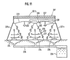
- angle panels 220 arranged in a plurality of rows (three rows in the figures), each consisting of two panels 221 with the top edges joined, having a number of holes to support the plants 222 of which the roots are projected inside the panels 221. Both ends of the rows are connected to side walls 201a, and both sides are closed with side walls 201c. Top edges of the adjacent angle panels 220 are connected with canopies 223 having an angular cross-section to prevent diffusion of light to the upper side, forming nearly triangular-sectioned spaces surrounded by the adjacent angle panels 220 and the canopies 223.
- An exhaust duct 202 as an exhaust means is provided at the center of the canopy 223, and lighting apparatus 228 are disposed under the exhaust duct 202, which are arranged with nearly equal spacings along the longitudinal direction of the angle panels 220.
- a hydroponic solution spraying mechanism 224 inside the angle panels 220, as a hydroponic solution feeding mechanism to feed the hydroponic solution or the like to the roots of the plants 222.
- the hydroponic solution spraying mechanism 224 is connected to a pump (not shown) with a polyvinyl chloride pipe to pump the hydroponic solution stored in a hydroponic solution tank 225 which is disposed underground outside the plant cultivation room.
- the hydroponic solution spraying mechanism 224 can be as used in the first embodiment described above.
- the hydroponic solution sprayed and accumulated on the floor is collected through a collection passage 226.
- the inner surface of a ceiling 201b of the plant cultivation room 201 is provided with a heat-insulating material 227.
- the air supply ports 203 are formed at both corners of the plant cultivation room 201.
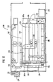
- a seedling culture line 232 in the plant cultivation factory 230 in addition to the above-described cultivation lines 231, and the seedling culture line 232 is also air-conditioned by an air-conditioning unit 233.
- the seedling culture line 232 can also be controlled for the carbon dioxide concentration as needed, as described above.
- cooling towers 234 and 235 for the air-conditioning units 204 and 233 outside the plant cultivation factory 230.
- the air supply port 209 is disposed in the exhaust duct 205 and the carbon dioxide outlet port 211 is in the air supply duct 206, these ports can also be disposed in reverse.
Landscapes
- Life Sciences & Earth Sciences (AREA)
- Environmental Sciences (AREA)
- Hydroponics (AREA)
Claims (13)
- Hydroponisches Aufzuchtsystem, umfassend
eine dachförmige Plattenstruktur (3, 220) mit Löchern zur Aufnahme von mit ihren Wurzeln in die Plattenstruktur hineinragenden Pflanzen (2, 222), und
einem Sprühmechanismus (11, 224) zur Zuführung einer hydroponischen Lösung an die Pflanzenwurzeln von der Innenseite der Plattenstruktur her,
dadurch gekennzeichnet, daß der Sprühmechanismus umfaßt:
einen an einem Untergestell (114) montierten Ständer (115) mit daran vorgesehenen Düsen (116) zum Besprühen der Pflanzenwurzeln mit der Lösung,
eine selbstfahrende Einrichtung (117-119) zum Hin- und Herbewegen des Untergestells (114) in Längsrichtung der Plattenstruktur (3, 220), und
eine Einrichtung (125, 126) zum Erfassen der Position des Untergestells (114) an beiden Enden der Plattenstruktur (3, 220). - System nach Anspruch 1, wobei mehrere Plattenstrukturen (3, 220) in einem mit einer Klimatisierungseinrichtung (202-214) ausgerüsteten Pflanzenaufzuchtraum (1, 201) angeordnet sind.
- Hydroponisches Aufzuchtsystem, umfassend
eine dachförmige Plattenstruktur (3, 220) mit Löchern zur Aufnahme von mit ihren Wurzeln in die Plattenstruktur hineinragenden Pflanzen (2, 222),
einen Pflanzenaufzuchtraum (1, 201), in dem die Plattenstruktur (3, 220) untergebracht ist,
einen Sprühmechanismus (224) zur Zuführung einer hydroponischen Lösung an die Pflanzenwurzeln von der Innenseite der Plattenstruktur her, und
eine Klimatisierungseinrichtung (202-214) zur Klimatisierung des Pflanzenaufzuchtraums (1, 201),
dadurch gekennzeichnet,
daß der Pflanzenaufzuchtraum (1, 201) so ausgebildet ist, daß er Sonnenlicht von den Pflanzen abhält, und ein Gerät (6, 228) zum Beregnen der Pflanzen (2, 222) enthält, und
daß die Klimatisierungseinrichtung umfaßt:
ein Gerät (209) zum Messen der Kohlendioxidkonzentration der Luft, von der Proben in einer Abluftleitung (205), die an den Pflanzenaufzuchtraum (201) zum Leiten von Luft aus diesem zu einer Luftkonditioniereinheit (204) angeschlossen ist, oder in einer Zuluftleitung (206) entnommen werden, die mit derselben Luftkonditioniereinheit (204) als Abluftleitung (205) verbunden und an den Pflanzenaufzuchtraum (201) zum Zuführen von durch die Luftkonditioniereinheit (204) aufbereiteter Luft angeschlossen ist,
eine mit der Abluftleitung (205) oder der Zuluftleitung (206) in Verbindung stehende Kohlendioxid-Auslaßöffnung (211),
eine die Auslaßöffnung (211) mit einer Kohlendioxidversorgung (212) verbindende Kohlendioxid-Zuführleitung (213) mit einem Elektromagnetventil (214), und
eine Steuereinrichtung (210) zur Steuerung des Ventils (214) gemäß dem Ausgangssignal des Kohlendioxidkonzentrations-Messgerätes (209) zur Einstellung der Kohlendioxidkonzentration in dem Pflanzenaufzuchtraum (201) auf einen vorgegebenen Wert. - System nach einem der Ansprüche 1 bis 3, wobei die Plattenstruktur (3, 220) aus zwei an ihren Oberkanten miteinander verbundenen Platten (3a, 221) besteht.
- System nach einem der Ansprüche 1 bis 4, wobei mehrere Plattenstrukturen (3, 220) parallel zueinander angeordnet sind.
- Hydroponisches Aufzuchtsystem, umfassend
mehrere in Reihen angeordnete dachförmige Plattenstrukturen (3, 220), deren jede Löcher zur Aufnahme von mit ihren Wurzeln in die Plattenstruktur hineinragenden Pflanzen (2, 222) aufweist,
einen Pflanzenaufzuchtraum (1, 201), in dem die mehreren Plattenstrukturen (3, 220) untergebracht sind, und
einen Sprühmechanismus (11, 224) zur Zuführung einer hydroponischen Lösung an die Pflanzenwurzeln von der Innenseite der Plattenstruktur her,
dadurch gekennzeichnet, daß der Pflanzenaufzuchtraum (1, 201) so ausgebildet ist, daß er Sonnenlicht von den Pflanzen (2, 222) abhält, und umfaßt:
eine Beleuchtungseinrichtung (6, 228) zum Bestrahlen der Pflanzen (2, 222),
Baldachine (4, 223), die die Oberkanten der Plattenstrukturen (3, 220) benachbarter Reihen verbinden und dadurch zwischen benachbarten Plattenstrukturen Räume mit im wesentlichen dreieckigen Querschnitt bilden, und
in der Umgebung der Beleuchtungseinrichtung (6, 228) angeordneter Abluftöffnungen (7, 202), wobei die Beleuchtungseinrichtung und die Abluftöffnungen an der unteren Fläche der Baldachine (4, 223) angeordnet sind. - System nach Anspruch 6, wobei die Baldachine (4, 223) einen bogenförmigen oder eckigen Querschnitt aufweisen.
- System nach Anspruch 6 oder 7, wobei an der unteren Fläche der Baldachine (4, 223) reflektierende Flächen angeordnet sind.
- System nach einem der Ansprüche 6 bis 8, wobei die Beleuchtungseinrichtung (6) eine eine Lichtquelle (6) umgebende Abdeckung (6b) aufweist und die Abluftöffnung (7) zwischen der Lichtquelle und der Abdeckung angeordnet ist.
- System nach einem der Ansprüche 6 bis 9, mit einer Einrichtung (202-214) zur Klimasteuerung in dem Pflanzenaufzuchtraum (1, 201).
- System nach Anspruch 2 oder 10, wobei die Klimasteuereinrichtung umfaßt:
ein Gerät (209) zum Messen der Kohlendioxidkonzentration der Luft, von der Proben in einer Abluftleitung (205), die an den Pflanzenaufzuchtraum (201) zum Leiten von Luft aus diesem zu einer Luftkonditioniereinheit (204) angeschlossen ist, oder in einer Zuluftleitung (206) entnommen werden, die mit derselben Luftkonditioniereinheit (204) als Abluftleitung (205) verbunden und an den Pflanzenaufzuchtraum (201) zum Zuführen von durch die Luftkonditioniereinheit (204) aufbereiteter Luft angeschlossen ist,
eine mit der Abluftleitung (205) oder der Zuluftleitung (206) in Verbindung stehende Kohlendioxid-Auslaßöffnung (211),
eine die Auslaßöffnung (211) mit einer Kohlendioxidversorgung (212) verbindende Kohlendioxid-Zuführleitung (213) mit einem Elektromagnetventil (214), und
eine Steuereinrichtung (210) zur Steuerung des Ventils (214) gemäß dem Ausgangssignal des Kohlendioxidkonzentrations-Messgerätes (209) zur Einstellung der Kohlendioxidkonzentration in dem Pflanzenaufzuchtraum (201) auf einen vorgegebenen Wert. - System nach einem der Ansprüche 6 bis 10, wobei der Srühmechanismus umfaßt:
einen an einem Untergestell (114) montierten Ständer (115) mit daran vorgesehenen Düsen (116) zum Besprühen der Pflanzenwurzeln mit der Lösung,
eine selbstfahrende Einrichtung (117-119) zum Hin- und Herbewegen des Untergestells (114) in Längsrichtung der Plattenstruktur (3, 220), und
eine Einrichtung (125, 126) zum Erfassen der Position des Untergestells (114) an beiden Enden der Plattenstruktur (3, 220). - System nach Anspruch 1 oder 2, wobei die selbstfahrende Einrichtung (117-119) einen unter einer Grundplatte (114) angeordneten Antriebsmotor (117) sowie ein auf der Welle des Motors (117) angeordnetes Kettenrad (118) umfaßt, das mit einer in Längsrichtung der Plattenstruktur (220) verlaufenden Kette (119) in Eingriff steht.
Priority Applications (1)
| Application Number | Priority Date | Filing Date | Title |
|---|---|---|---|
| AT87107422T ATE68065T1 (de) | 1986-05-21 | 1987-05-21 | Hydroponisches anbausystem. |
Applications Claiming Priority (6)
| Application Number | Priority Date | Filing Date | Title |
|---|---|---|---|
| JP114742/86 | 1986-05-21 | ||
| JP61114742A JPS62272922A (ja) | 1986-05-21 | 1986-05-21 | 植物栽培方法及びこれに用いる植物栽培装置 |
| JP25701486A JPS63112928A (ja) | 1986-10-30 | 1986-10-30 | 環境制御方法及び植物栽培室の炭酸ガス濃度制御装置 |
| JP257014/86 | 1986-10-30 | ||
| JP61276720A JPS63129940A (ja) | 1986-11-21 | 1986-11-21 | 水耕栽培装置 |
| JP276720/86 | 1986-11-21 |
Publications (2)
| Publication Number | Publication Date |
|---|---|
| EP0247527A1 EP0247527A1 (de) | 1987-12-02 |
| EP0247527B1 true EP0247527B1 (de) | 1991-10-09 |
Family
ID=27312806
Family Applications (1)
| Application Number | Title | Priority Date | Filing Date |
|---|---|---|---|
| EP87107422A Expired - Lifetime EP0247527B1 (de) | 1986-05-21 | 1987-05-21 | Hydroponisches Anbausystem |
Country Status (5)
| Country | Link |
|---|---|
| EP (1) | EP0247527B1 (de) |
| CA (1) | CA1308909C (de) |
| DE (1) | DE3773541D1 (de) |
| IL (1) | IL82526A0 (de) |
| NO (1) | NO167491C (de) |
Cited By (4)
| Publication number | Priority date | Publication date | Assignee | Title |
|---|---|---|---|---|
| CN105532319A (zh) * | 2015-12-30 | 2016-05-04 | 东北农业大学 | 一种面向闭锁式立体育秧平台的智能化气流调控系统 |
| CN105580665A (zh) * | 2015-12-15 | 2016-05-18 | 东北农业大学 | 一种基于人工光源技术的闭锁式立体智能化育秧平台系统 |
| US11589517B2 (en) * | 2014-07-31 | 2023-02-28 | Living Greens Farm, Inc. | Growing system |
| US11678621B2 (en) | 2018-03-31 | 2023-06-20 | Living Greens Farm, Inc. | Growing system |
Families Citing this family (5)
| Publication number | Priority date | Publication date | Assignee | Title |
|---|---|---|---|---|
| US6000173A (en) * | 1998-08-05 | 1999-12-14 | Schow; Matthew Alan | Hydroponic growing station with intermittent nutrient supply |
| CA2670273C (en) * | 2006-11-20 | 2016-04-05 | Grassroots Biotechnology, Inc. | Plant growth and imaging devices and related methods and computer program products |
| US10111394B2 (en) * | 2012-12-18 | 2018-10-30 | Garden Fresh Farms Llc | Plant growing system |
| WO2016061672A1 (en) | 2014-10-21 | 2016-04-28 | Avid Growing Systems Inc. | System, apparatus and method for growing marijuana |
| CN111264373A (zh) * | 2020-03-17 | 2020-06-12 | 河南科技学院 | 一种甘薯苗培养装置 |
Family Cites Families (2)
| Publication number | Priority date | Publication date | Assignee | Title |
|---|---|---|---|---|
| CA1005366A (fr) * | 1972-12-08 | 1977-02-15 | Institut Francais Du Petrole | Conduite flexible etanche |
| FI69389C (fi) * | 1984-03-27 | 1986-02-10 | Laennen Tehtaat Oy | Bevattningsanordning |
-
1987
- 1987-05-13 CA CA000537011A patent/CA1308909C/en not_active Expired - Lifetime
- 1987-05-14 IL IL82526A patent/IL82526A0/xx unknown
- 1987-05-20 NO NO872112A patent/NO167491C/no unknown
- 1987-05-21 DE DE8787107422T patent/DE3773541D1/de not_active Expired - Lifetime
- 1987-05-21 EP EP87107422A patent/EP0247527B1/de not_active Expired - Lifetime
Cited By (5)
| Publication number | Priority date | Publication date | Assignee | Title |
|---|---|---|---|---|
| US11589517B2 (en) * | 2014-07-31 | 2023-02-28 | Living Greens Farm, Inc. | Growing system |
| CN105580665A (zh) * | 2015-12-15 | 2016-05-18 | 东北农业大学 | 一种基于人工光源技术的闭锁式立体智能化育秧平台系统 |
| CN105532319A (zh) * | 2015-12-30 | 2016-05-04 | 东北农业大学 | 一种面向闭锁式立体育秧平台的智能化气流调控系统 |
| CN105532319B (zh) * | 2015-12-30 | 2018-04-03 | 东北农业大学 | 一种面向闭锁式立体育秧平台的智能化气流调控系统 |
| US11678621B2 (en) | 2018-03-31 | 2023-06-20 | Living Greens Farm, Inc. | Growing system |
Also Published As
| Publication number | Publication date |
|---|---|
| CA1308909C (en) | 1992-10-20 |
| NO167491C (no) | 1991-11-13 |
| NO872112D0 (no) | 1987-05-20 |
| NO872112L (no) | 1987-11-23 |
| IL82526A0 (en) | 1987-11-30 |
| NO167491B (no) | 1991-08-05 |
| DE3773541D1 (de) | 1991-11-14 |
| EP0247527A1 (de) | 1987-12-02 |
Similar Documents
| Publication | Publication Date | Title |
|---|---|---|
| US4965962A (en) | Hydroponic culture system | |
| US11412668B2 (en) | Greenhouse and forced greenhouse climate control system and method | |
| JP2019141082A (ja) | 植物栽培装置、植物栽培方法及び栽培トレイ | |
| EP0247527B1 (de) | Hydroponisches Anbausystem | |
| JPH0511924B2 (de) | ||
| JPH10215701A (ja) | 植物工場 | |
| EP0288670A1 (de) | Hydrokultursystem | |
| DE4004154A1 (de) | Gewaechshausregal | |
| EP0051647B1 (de) | Vorrichtung zum kultivieren von pflanzen in einer programmierten umwelt | |
| GB2234147A (en) | Process and means for geodesic dome crop production | |
| JPH01235524A (ja) | 完全制御型植物工場 | |
| JP2000004672A (ja) | 植物の人工栽培方法及び装置 | |
| JPS61282025A (ja) | 水耕栽培装置 | |
| JPH064005B2 (ja) | 植物栽培用温室 | |
| JPS6374429A (ja) | 葉菜類の水耕栽培施設 | |
| AT241191B (de) | Vorrichtung zur künstlichen Züchtung von Pflanzen, Bakterien u. ähnl. Lebewesen | |
| JPH03187321A (ja) | 断熱暗室における植物栽培方法 | |
| NL2034755B1 (en) | A construction for cultivating plants in an at least substantially daylight-free growing section thereof | |
| JPH0463656B2 (de) | ||
| JP7287646B2 (ja) | 植物栽培装置及び植物製造方法 | |
| JPH03191725A (ja) | 可搬式人工光型植物栽培装置 | |
| JPH0549250B2 (de) | ||
| JP2000209969A (ja) | 植物栽培装置 | |
| JP2001045878A (ja) | 温室作物の加湿装置 | |
| JPH01128729A (ja) | 植物育成装置 |
Legal Events
| Date | Code | Title | Description |
|---|---|---|---|
| PUAI | Public reference made under article 153(3) epc to a published international application that has entered the european phase |
Free format text: ORIGINAL CODE: 0009012 |
|
| AK | Designated contracting states |
Kind code of ref document: A1 Designated state(s): AT BE CH DE ES FR GB GR IT LI LU NL SE |
|
| 17P | Request for examination filed |
Effective date: 19880429 |
|
| 17Q | First examination report despatched |
Effective date: 19900118 |
|
| GRAA | (expected) grant |
Free format text: ORIGINAL CODE: 0009210 |
|
| AK | Designated contracting states |
Kind code of ref document: B1 Designated state(s): AT BE CH DE ES FR GB GR IT LI LU NL SE |
|
| PG25 | Lapsed in a contracting state [announced via postgrant information from national office to epo] |
Ref country code: BE Effective date: 19911009 Ref country code: AT Effective date: 19911009 Ref country code: CH Effective date: 19911009 Ref country code: GR Free format text: LAPSE BECAUSE OF FAILURE TO SUBMIT A TRANSLATION OF THE DESCRIPTION OR TO PAY THE FEE WITHIN THE PRESCRIBED TIME-LIMIT Effective date: 19911009 Ref country code: LI Effective date: 19911009 Ref country code: IT Free format text: LAPSE BECAUSE OF FAILURE TO SUBMIT A TRANSLATION OF THE DESCRIPTION OR TO PAY THE FEE WITHIN THE PRE;WARNING: LAPSES OF ITALIAN PATENTS WITH EFFECTIVE DATE BEFORE 2007 MAY HAVE OCCURRED AT ANY TIME BEFORE 2007. THE CORRECT EFFECTIVE DATE MAY BE DIFFERENT FROM THE ONE RECORDED.SCRIBED TIME-LIMIT Effective date: 19911009 |
|
| REF | Corresponds to: |
Ref document number: 68065 Country of ref document: AT Date of ref document: 19911015 Kind code of ref document: T |
|
| REF | Corresponds to: |
Ref document number: 3773541 Country of ref document: DE Date of ref document: 19911114 |
|
| PG25 | Lapsed in a contracting state [announced via postgrant information from national office to epo] |
Ref country code: ES Free format text: LAPSE BECAUSE OF FAILURE TO SUBMIT A TRANSLATION OF THE DESCRIPTION OR TO PAY THE FEE WITHIN THE PRESCRIBED TIME-LIMIT Effective date: 19920120 |
|
| REG | Reference to a national code |
Ref country code: CH Ref legal event code: PL |
|
| EN | Fr: translation not filed | ||
| PG25 | Lapsed in a contracting state [announced via postgrant information from national office to epo] |
Ref country code: FR Effective date: 19920228 |
|
| PG25 | Lapsed in a contracting state [announced via postgrant information from national office to epo] |
Ref country code: LU Free format text: LAPSE BECAUSE OF NON-PAYMENT OF DUE FEES Effective date: 19920531 |
|
| PLBE | No opposition filed within time limit |
Free format text: ORIGINAL CODE: 0009261 |
|
| STAA | Information on the status of an ep patent application or granted ep patent |
Free format text: STATUS: NO OPPOSITION FILED WITHIN TIME LIMIT |
|
| 26N | No opposition filed | ||
| PG25 | Lapsed in a contracting state [announced via postgrant information from national office to epo] |
Ref country code: DE Effective date: 19930202 |
|
| REG | Reference to a national code |
Ref country code: FR Ref legal event code: ST |
|
| EAL | Se: european patent in force in sweden |
Ref document number: 87107422.5 |
|
| PGFP | Annual fee paid to national office [announced via postgrant information from national office to epo] |
Ref country code: SE Payment date: 19980316 Year of fee payment: 12 |
|
| PGFP | Annual fee paid to national office [announced via postgrant information from national office to epo] |
Ref country code: GB Payment date: 19980512 Year of fee payment: 12 |
|
| PGFP | Annual fee paid to national office [announced via postgrant information from national office to epo] |
Ref country code: NL Payment date: 19980531 Year of fee payment: 12 |
|
| PG25 | Lapsed in a contracting state [announced via postgrant information from national office to epo] |
Ref country code: GB Free format text: LAPSE BECAUSE OF NON-PAYMENT OF DUE FEES Effective date: 19990521 |
|
| PG25 | Lapsed in a contracting state [announced via postgrant information from national office to epo] |
Ref country code: SE Free format text: LAPSE BECAUSE OF NON-PAYMENT OF DUE FEES Effective date: 19990522 |
|
| PG25 | Lapsed in a contracting state [announced via postgrant information from national office to epo] |
Ref country code: NL Free format text: LAPSE BECAUSE OF NON-PAYMENT OF DUE FEES Effective date: 19991201 |
|
| GBPC | Gb: european patent ceased through non-payment of renewal fee |
Effective date: 19990521 |
|
| EUG | Se: european patent has lapsed |
Ref document number: 87107422.5 |
|
| NLV4 | Nl: lapsed or anulled due to non-payment of the annual fee |
Effective date: 19991201 |