EP0247300B1 - Automatische Maschine zur Herstellung von Wellpappe - Google Patents
Automatische Maschine zur Herstellung von Wellpappe Download PDFInfo
- Publication number
- EP0247300B1 EP0247300B1 EP87103312A EP87103312A EP0247300B1 EP 0247300 B1 EP0247300 B1 EP 0247300B1 EP 87103312 A EP87103312 A EP 87103312A EP 87103312 A EP87103312 A EP 87103312A EP 0247300 B1 EP0247300 B1 EP 0247300B1
- Authority
- EP
- European Patent Office
- Prior art keywords
- station
- cardboard
- machine according
- machine
- frame
- Prior art date
- Legal status (The legal status is an assumption and is not a legal conclusion. Google has not performed a legal analysis and makes no representation as to the accuracy of the status listed.)
- Expired - Lifetime
Links
Images


Classifications
-
- B—PERFORMING OPERATIONS; TRANSPORTING
- B31—MAKING ARTICLES OF PAPER, CARDBOARD OR MATERIAL WORKED IN A MANNER ANALOGOUS TO PAPER; WORKING PAPER, CARDBOARD OR MATERIAL WORKED IN A MANNER ANALOGOUS TO PAPER
- B31B—MAKING CONTAINERS OF PAPER, CARDBOARD OR MATERIAL WORKED IN A MANNER ANALOGOUS TO PAPER
- B31B50/00—Making rigid or semi-rigid containers, e.g. boxes or cartons
- B31B50/006—Controlling; Regulating; Measuring; Improving safety
-
- B—PERFORMING OPERATIONS; TRANSPORTING
- B31—MAKING ARTICLES OF PAPER, CARDBOARD OR MATERIAL WORKED IN A MANNER ANALOGOUS TO PAPER; WORKING PAPER, CARDBOARD OR MATERIAL WORKED IN A MANNER ANALOGOUS TO PAPER
- B31B—MAKING CONTAINERS OF PAPER, CARDBOARD OR MATERIAL WORKED IN A MANNER ANALOGOUS TO PAPER
- B31B50/00—Making rigid or semi-rigid containers, e.g. boxes or cartons
- B31B50/14—Cutting, e.g. perforating, punching, slitting or trimming
- B31B50/16—Cutting webs
Definitions
- the present invention relates to an automatic machine for the processing of corrugated paper in order to obtain containers according to the preamble of claim 1.
- Such machines are generally known.
- the machines currently known for providing said containers allow the manufacturing of a single product, or more than one but with features which are very similar to each other in dimensions and type of stiffening or reinforcement.
- the main aim of the present invention is therefore to eliminate the disadvantages described above in known types by devising an automatic machine which allows to obtain containers in corrugated cardboard which are provided, according to the specific requirements, with the required dimensions and the desired stiffenings and reinforcements.
- a further important object is to devise a machine which associates to the previous characteristics that of being provided with high flexibility in use, allowing, at the same time, to obtain a product which can be stored optimally.
- Another object is to provide a machine which allows to obtain, in sequence, containers having even different dimensions and characteristics from one to the next.
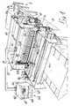
- the machine 1 is composed of a first station 2 for the multiple feed of corrugated paper or cardboard 3.
- rolls of cardboard have been positioned at the station 2, which comprises a supporting frame 4 to the side members of which the shafts 5 of three rolls, indicated with the reference numerals 6a, 6b and 6c, are freely pivoted.
- Each roll may be composed of corrugated cardboard having a different width and/or different length.
- the cardboard of the rolls 6a and 6b is unrolled by making it slide on free rollers 7a and 7b arranged below and transversely with respect to the frame 4.
- rollers lie in planes arranged parallel to each other, between the same and the ground there being provided separation rods indicated with the reference numerals 8 and 9.
- a brake 10 is associated to one of the ends of the shafts 5.
- Said brake is composed of two identical jaws 11a and 11b arranged diametrically with respect to the shaft 5 and placed on a plane which is perpendicular thereto.
- Each jaw is provided with a throat, arranged concentrically with respect to the shaft 5, to which a rubber crown 12 is rigidly coupled; the two jaws are mutually associated to each other by means of screws 13 concentrically to which springs 14 are arranged which interact with the facing surfaces of the jaws.
- the lower jaw 11a rotating together with the shaft 5 during the unrolling, interacts with a pin 15 which projects from the frame 4.
- Said pin which is provided with an axis parallel to the one of the shaft, thus allows the brake 10 to always keep the corrugated cardboard 3 at the optimum tension.
- the shaft 5 is indeed gripped vice-like during the interaction with said pin.
- the station 2 can be composed of a plurality of frames 4 joined to each other so as to allow the use of cardboard rolls having different characteristics.
- the second station 16 for the insertion of the cardboard, is provided, composed of a supporting frame 17 which supports a lifting assembly 18.
- the frame 17 is provided with two rectangular lateral shoulders 19, provided, on the side arranged proximate to the first station, with a pair of free transverse rollers 20a and 20b, the axes of which are arranged on the same plane as those of the rollers 7a and 7b.
- the roller 21c takes up the cardboard directly from the roll 6c, as illustrated in Fig. 2.
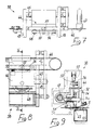
- the lifting assembly 18 is composed of two identical rectangular lateral plates 22a and 22b, transversely to which three pairs of rollers are pivoted, each being indicated with the reference numeral 23, the axes of which, parallel to each other, are arranged on the same plane, perpendicular to the base or rest plane of the station.
- Each pair of rollers 23 is composed of a motorized roller 24, driven by a suitable motor 25, and of a free counter-roller 26, the axis 27 of which is associated, at each end, to a slot 28 with à vertical axis formed on the plates 22a and 22b.
- Each end of the axis 27 is furthermore engaged in a groove 29 provided on the stem of a swinging element 30, which is essentially Y-shaped, and freely pivoted to the plates 22a and 22b at the terminal end of the stem facing opposite to the station 2.
- a shaft 31 is provided, mounted on an eccentric element 32, which can be operated by means of a lever 33.
- the axis 27 of the counter-roller 26 is raised or lowered, thus allowing its uncoupling-coupling with the motorized roller 24.
- Fig. 18 illustrates another aspect of the invention, in which two eccentric elements, indicated with the reference numerals 114 and 115, are associated to the end of the axis 27 of the free counter-roller 26, which eccentric elements are rotatably associated with the lateral plates 22a and 22b.
- the angular position of the eccentric element 115 can be varied by means of the lever 33, it being possible to fix said lever, by means of a suitable locking element interposed between said lever and the plate 22a, in a preset position.
- the vertical motion of the lifting assembly 18 is imparted by means of a pair of chains 34, each of which is provided with its ends associated to the upper and lower ones of one of the plates 22a and 22b.
- two toothed wheels are provided, indicated with the reference numerals 35a and 35b: the first wheel 35a is keyed on the axis of a motor and reducer assembly 36, while the second wheel 35b is freely rotatable.
- oscillable bars 41, slideable on crosspieces 42 are provided, suitable for allowing the exact centering of the cardboard with respect to the middle longitudinal axis of the machine 1, which axis may be indicated hereinafter as the operating axis.
- combs 43 are provided which are adapted for facilitating the insertion of the cardboard selected among the three available by the lifting assembly 18.
- Figures 19 and 20 illustrate an aspect of the invention which is adapted for maintaining the cardboard straight in case the cardboard is uneven in its dimensions due, e.g., to thermal changes it has been subject to. This is obtained by providing the adjustment of the position of the lifting assembly 18 by rigidly coupling to the plate 22b a pair of U-shaped tabs 40, and closed at the free end by an abutment 116. Inside each of said tabs, sliders 117 are slideable and accommodatable, and the wheel 39a and the pulley 39b are pivoted thereto and interact with the shaft 37.
- Said sliders 117 are rigidly mutually interconnected by means of a beam 118.
- the terminal end of the stem 119 of a piston 120, connected to the plate 22b, is associated proximate to the middle portion of said beam.
- the operation of the piston 120 allows the angular motion of the entire lifting assembly 18 with respect to the plane of arrangement of the shafts 37, fixed to the shoulders 19, until it straightens and thus allows to center the cardboard for subsequent processing.
- the cutting station 38 is composed of a cutter assembly which comprises a supporting frame 44, pivoted to a transverse guiding rail 45 and moved by means of a chain 46 operated by a suitable motor and reducer assembly 47.
- the frame 44 accommodates a tempered rotating blade 48, arranged on a plane which is transverse with respect to the machine 1; the blade is of the self-sharpening type, since it cooperates with a replaceable fixed abutment blade 49, above which the cardboard is pushed by means of the roller 24.
- the blade 48 is freely pivoted on a small shaft 50, which is connected to the frame 44; a spring 51, coaxial to the small shaft, allows a regular motion of the blade 48 and an adequate pressure on the fixed abutment blade 49.
- a cylinder with trapezoidal cross section 52 is arranged to the side of the latter, which cylinder interacts, during the transverse motion of the frame 44, with the ends of a metal strap 53 tilted towards the cardboard feed region and, at the other end, pivoted to a transverse axis.
- the blade 48 is fixed coaxially with respect to the cylinder 52.
- the strap thus blocks the corrugated cardboard in the cutting phase, preventing the formation of burr.
- At least one elastically deformable element 54 is associable with the strap, for adjusting the inclination thereof; accordingly, the blade 48 can also assume a desired angle with respect to the fixed blade 49.
- a biasing bar 55 is provided above the frame 44, which bar interacts with a connecting rod 56 by means of a bearing 57 freely pivoted thereto.
- Said connecting rod is in turn freely pivoted, at one end, to the frame 44; between the other end and said frame, a cylindrical helical compression spring 58 is instead interposed.
- a fourth station 59 follows for the scoring of the corrugated cardboard.
- said station is composed of three pairs of scorers, each scorer of the three pairs being indicated with the reference numerals 60a, 60b and 60c.
- Each scorer of each pair is pivoted on a transverse shaft 61 and is associated to a fork 62, upwardly provided with a cylindrical guide 63 which is slideable on a transverse shaft 64, which is fixed and parallel to the previous one.
- Each scorer of each pair can furthermore be positioned symmetrically with respect to the operating axis of the machine 1 by means of a suitable worm screw 65.
- Said worm screw is arranged transversely with respect to the station along an axis which is parallel to the one of the shafts 61 and 64 and is associated to the fork 62 by means of a bush 66.
- a locking ring 67 associable to the bush 66, allows the manual adjustment of the initial position of each scorer, so that each pair of scorers is arranged symmetrically with respect to the operating axis of the machine.
- each worm screw 65 is motorized with its own motor and reducer assembly 68.
- said worm screw has formed thereon half a left-handed thread and half a right-handed thread.
- Each scorer interacts with a roller 69, placed below and provided with an axis parallel to the one of the small shaft 61, allowing to perform the longitudinal scoring of the cardboard.
- the ends of said roller 69 are mounted on eccentric elements so as to permit adjustment of its parallelism with respect to the shaft 61 to thus allow the optimum scoring of the corrugated cardboard 3.
- a single motor 70 instead, controls the rotation of the shaft 61 of the scorer 60c and therefore, by means of suitable transmissions constituted by toothed wheels 71 interacting with matchingly toothed wheels keyed to one end of the shafts 61 of the scorers 60a, 60b and 60c, the advancement of the corrugated cardboard 3.
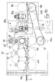
- the fifth station is provided for the punching or dinking of said cardboard.
- the fifth station is composed of two dinking bodies 72a and 72b which comprise a box-like supporting frame 73a and 73b, pivoted laterally to a transverse guiding rail 74.
- the two dinking bodies operate by moving simultaneously towards the operating axis of the machine 1: indeed, the chain 75 is associated, in the upper part, to the frame 73a of the right-hand punching body 72a (Fig. 13) and, in the lower part, to the frame 73b of the left-hand punching body 72b (Fig. 12).
- Each frame 73a and 73b accommodates a pair of identical, mutually counterposed rotating blades 78, which are furthermore mutually blocked between two disks 79a and 79b to ensure their parallelism.
- Said blades are mounted on the same small shaft 80 arranged transversely with respect to the frame, are allowed an axial clearance, and are spaced from the inner surfaces of the frame.
- a cylindrical helical spring 81 is arranged interposed between the inner surfaces of the disks.
- a cylinder with a trapezoidal cross section 82 is coaxially associated to the disk 79a and interacts, during the transverse motion of the dinking body, with the end of a transverse metal strap 83 tilted towards the side where the cardboard 3 is fed, and associated at the other end to an axis arranged transversely with respect to the machine.
- Said strap thus blocks, similarly to what occurred for the cutter assembly, the corrugated cardboard 3 during the dinking.
- the dinking body furthermore comprises two fixed abutment blades 84a and 84b, arranged on the plane of the cardboard, replaceable and arranged mutually parallel with such an interspace as to allow the passage of the blades 78, and having moreover such a shape as to make the latter self-sharpening.
- At least one elastically deformable means 85 is associable with the strap 83, between the two ends, which means adjusts the inclination of the blades 78, since the frame 73a and 73b can swing slightly with respect to the guiding bar 74.
- each frame 73a and 73b is upwardly provided with a connecting rod 86 interacting, by means of a bearing 87 pivoted freely thereto proximate to the middle portion, with a biasing bar 88.
- the connecting rod is freely pivoted, at one end, to the frame of the dinking body, between the other end and said frame there being interposed a cylindrical helical spring 89.
- each dinking body can be moved out of the lateral shoulders 90 of the station in order to perform operations.
- the ends of the chain 75 are associated with the frames 73a and 73b so that their position can be adjusted until it is symmetrical with respect to the operating axis of the machine.
- each frame 73a and 73b is provided with a mechanical stroke limit at the location of a blade which is fixed to and projects from the pair of scorers 60c, which is closest to the operating axis of the machine.
- Each dinking body is furthermore provided with means adapted for the removal of the strip of cardboard obtained during the dinking.
- Said means illustrated in Fig. 13, comprises a magnet 91, associated to the frame to the rear of the work area of the blades, which magnet controls the motion, along a vertical axis, of a small bar 92 to which an arm 93 is downwardly freely pivoted and is angled and arranged on a plane passing through the connecting plane of the pair of blades 78.
- One end of said arm 93, adjacent to the pivoting point of the small bar 92, is in turn freely pivoted to the frame whilst at the other end of the arm 93, underlying the pair of blades 78, there is associated a blade 94, facing towards the direction of said blades 78.
- the end of the blade 94 is arranged on a plane which is lower than the rest plane of the cardboard: when the magnet is activated, the small bar 92 is drawn upwards, raising the arm 93 and thus causing the blade 94 cut the terminal end of the cardboard strip.
- a suitable switch keeps the magnet activated for a fraction of a second while the punching body is returned to a position proximate to the walls 90: this allows the tearing off of the cardboard strip if it has not been cut off previously.
- the sixth station is provided at the outlet of the fifth station, which sixth station comprises a pair of transverse rollers 95a and 95b adapted for ensuring the outgoing entrainment of the cardboard, as well as the off-cuts or punchings.
- the motion occurs by means of a toothed belt 96 trained around toothed wheels 97a and 97b; the first wheel takes up the motion from the roller 69 and the second one transmits it to a roller 97c which moves the roller 95a which transmits the motion to the 95b, via the belf 96.
- a motorized set of rollers 98 is provided for the transport, the glueing and the folding of the flaps of the cardboard obtained by scoring.
- Said functions are obtainable by means of glue dispensers 99 and L-shaped swinging arms 100 hinged at the end of the shortest part.
- Both dispensers and arms may be moved transversely with respect to the set of rollers, and provided with a bush 101 interacting with a worm screw 102.
- the worm screw is operated by a single motor 103: the symmetry of the pairs of dispensers and arms with respect to the operating axis of the machine is allowed by virtue of the fact that the worm screws 102 are provided along half of their length with right-handed thread and along the other half of their length with a left-handed thread.
- the machine 1 finally comprises a means 104 for control and data input for the programing, command and control of the operating phases.
- Said means is constituted by a central logic unit contained within a box-like structure 105.
- the data can be input by means of a keyboard 106 and can be displayed on a monitor 107 or a printer 108 may be provided for printing the cardboard.
- a button panel 109 finally allows manual intervention in case of malfunction, as well as the verification, by means of suitable optical indicators, of the functionality of the various components.
- the machine 1 is furthermore provided with sensors and actuators so as to allow the control means 104 to command and control the various processing phases.
- the use of the machine 1 initially entails the positioning of the corrugated cardboard 3 of each roller 6a, 6b and 6c, each proximate to a pair of rollers 23.
- the oscillable or swinging bars 41 furthermore allow the exact centering of the cardboard with respect to the operating axis of the machine, said axis being the reference axis for the control means 104.
- control means 104 will command the actuation of the motor and reducer assembly 36, which positions the lifting assembly 18 so that the desired cardboard is positioned at the working plane of the third station 38.
- this is the cardboard of the roll 6b.
- the cardboard may be initially trimmed by the cutter assembly and then introduced into the fourth station.
- control means 104 will have positioned the scorers 60a, 60b and 60c in the required positions, so as to perform the required scorers or creases.
- the cardboard After passing beyond the last scorer 60c, the cardboard will enter in the fifth station, where the two dinking bodies 72a and 72b will perform the dinking of the cardboard, removing at the same time the strip of punched-off cardboard.
- control means 104 will have activated the cutter assembly of the third station 38, which will cut the cardboard once it reaches the required length.
- the invention achieves the intended aim and objects, an automatic machine being provided which allows one to obtain cardboard which is punched and scored or creased so as to obtain a container having the desired dimensions and reinforcements.
- the machine Since it is furthermore possible to preselect the cardboard of the required dimensions, the machine allows remarkable flexibility in use, it being possible to provide punched and scored cardboards for the obtainment of containers of any dimensions.
- one of the three scoring assemblies 60a, 60b and 60c may be replaced by a cutter assembly for the longitudinal cutting of the cardboard.
- an assembly-for the transverse scoring of the cardboard may be provided, positioned, for example, after the station 38.
- Fig. 17 illustrates the use of an oscillably mounted container 110 which contains glue 111 which is applied to the cardboard 3 by means of one or more brushes 112 connected to an outflow duct.
- the container can be refilled, is pivoted between two beams which constitute the frame 4, and its angle with respect to the plane of the underlying cardboard can be adjusted by means of a suitable screw 113 protruding, below the pivoting point of the container, from the beam of the frame.
- Said container allows, e.g., to stably and mutually associate two sheets of corrugated cardboard unrolled from two contiguous rollers so that they are associated with counterposed corrugations.
- the processed cardboard may have any dimensions and thickness, and it may be obtained by superimposing a plurality of individual sheets.
- each individual component of the machine may be any according to requirements.
Landscapes
- Making Paper Articles (AREA)
- Machines For Manufacturing Corrugated Board In Mechanical Paper-Making Processes (AREA)
- Packages (AREA)
- Paper (AREA)
Claims (31)
dadurch gekennzeichnet, dass die erste Station (2) so ausgebildet ist, dass sie die Mehrfacheinführung von Wellpappe auch mit unterschiedlichen Breiten erlaubt und dass sie einen Rahmen (4) aufweist, der drehbare Rollen (6a, 6b, 6c) von Wellpappe (3) trägt, die ggfs. unterschiedliche Eigenschaften wie z.B. Breiten und/oder Längen haben, und ferner Führungswalzen (7a, 7b, 20a, 20b, 21a, 21b, 21c) aufweist, welche die Wellpappe (3) von den Rollen (6a, 6b, 6c) in der Weise in die zweite Station (16) mehrfach führen, dass die von allen Rollen (6a, 6b, 6c) kommende Wellpappe in der zweiten Station (16) in parallelen Ebenen angeordnet ist,
und dass die zweite Station (16) so ausgebildet ist, dass durch sie Wellpappe mit unterschiedlichen Eigenschaften in den Verarbeitungsbereich der Maschine eingeführt wird, und einen zweiten Rahmen (17) aufweist, der eine Hebeeinrichtung (18) trägt, die für jede Rolle (6a, 6b, 6c) von Wellpappe (3) angetriebene Mittel (23, 30 bis 33) für das Einführen der Pappe (3) in den Verarbeitungsbereich der Maschine hat und in einer Richtung i.w. senkrecht zu den parallelen Ebenen der Wellpappe in der Weise linear beweglich ist, dass eine ausgewählte Art von Wellpappe in den Verarbeitungsbereich der Maschine eingebracht werden kann, wobei Steuer- und Dateneingabeeinrichtungen für das Programmieren, Steuern und Kontrollieren der Verarbeitungsvorgänge der Maschine und für das Bedrucken der Pappe vorgesehen sind.
Priority Applications (1)
| Application Number | Priority Date | Filing Date | Title |
|---|---|---|---|
| AT87103312T ATE64120T1 (de) | 1986-03-14 | 1987-03-09 | Automatische maschine zur herstellung von wellpappe. |
Applications Claiming Priority (2)
| Application Number | Priority Date | Filing Date | Title |
|---|---|---|---|
| IT8251586 | 1986-03-14 | ||
| IT82515/86A IT1189851B (it) | 1986-03-14 | 1986-03-14 | Macchina automatica per la lavorazione della carta ondulata |
Publications (2)
| Publication Number | Publication Date |
|---|---|
| EP0247300A1 EP0247300A1 (de) | 1987-12-02 |
| EP0247300B1 true EP0247300B1 (de) | 1991-06-05 |
Family
ID=11318154
Family Applications (1)
| Application Number | Title | Priority Date | Filing Date |
|---|---|---|---|
| EP87103312A Expired - Lifetime EP0247300B1 (de) | 1986-03-14 | 1987-03-09 | Automatische Maschine zur Herstellung von Wellpappe |
Country Status (5)
| Country | Link |
|---|---|
| EP (1) | EP0247300B1 (de) |
| AT (1) | ATE64120T1 (de) |
| DE (1) | DE3770522D1 (de) |
| ES (1) | ES2022180B3 (de) |
| IT (1) | IT1189851B (de) |
Families Citing this family (8)
| Publication number | Priority date | Publication date | Assignee | Title |
|---|---|---|---|---|
| IT1239571B (it) * | 1990-04-24 | 1993-11-08 | Panotec | Dispositivo per l'introduzione selettiva di diverse tipologie di cartone |
| IT1311095B1 (it) | 1999-10-15 | 2002-02-28 | Aetna Group Spa | Metodo per l' imballaggio di prodotti, apparecchiatura attuante talemetodo ed imballo cosi' ottenuto. |
| ES2182717B1 (es) * | 2001-07-27 | 2004-06-01 | Calderi, S.L. | Nuevo sistema de automatizacion, control y regulacion, para instalaciones de fabricacion de carton ondulado. |
| GB2542569B (en) * | 2015-09-22 | 2021-04-28 | Ds Smith Packaging Ltd | A combination of a printed roll and a print roll inventory map |
| CN114714673B (zh) * | 2022-03-29 | 2024-01-02 | 青州市祥力轻工设备有限公司 | 水帘块纸带连续瓦楞成形系统 |
| CN115302849B (zh) * | 2022-08-22 | 2025-05-13 | 广州亨雅实业集团有限公司 | 一种基于智能制造的高效异形表盒折边压泡装置 |
| CN115519836B (zh) * | 2022-10-21 | 2025-02-25 | 昆山美泰纸业有限公司 | 一种纸板生产用粘胶碾压装置 |
| CN117799234A (zh) * | 2023-11-16 | 2024-04-02 | 龙利得智能科技股份有限公司 | 一种用于印刷包装的瓦楞纸局部修补设备 |
Family Cites Families (3)
| Publication number | Priority date | Publication date | Assignee | Title |
|---|---|---|---|---|
| JPS5316944B2 (de) * | 1973-09-21 | 1978-06-05 | ||
| US4500381A (en) * | 1983-04-20 | 1985-02-19 | Longview Fibre Company | Method and apparatus for making multiple ply paperboard |
| DE3322387C2 (de) * | 1983-06-22 | 1986-01-30 | Werner H.K. Peters Maschinenfabrik Gmbh, 2000 Hamburg | Wellpappenmaschine |
-
1986
- 1986-03-14 IT IT82515/86A patent/IT1189851B/it active
-
1987
- 1987-03-09 AT AT87103312T patent/ATE64120T1/de not_active IP Right Cessation
- 1987-03-09 ES ES87103312T patent/ES2022180B3/es not_active Expired - Lifetime
- 1987-03-09 EP EP87103312A patent/EP0247300B1/de not_active Expired - Lifetime
- 1987-03-09 DE DE8787103312T patent/DE3770522D1/de not_active Expired - Fee Related
Also Published As
| Publication number | Publication date |
|---|---|
| EP0247300A1 (de) | 1987-12-02 |
| IT1189851B (it) | 1988-02-10 |
| ATE64120T1 (de) | 1991-06-15 |
| IT8682515A0 (it) | 1986-03-14 |
| DE3770522D1 (de) | 1991-07-11 |
| ES2022180B3 (es) | 1991-12-01 |
| IT8682515A1 (it) | 1987-09-14 |
Similar Documents
| Publication | Publication Date | Title |
|---|---|---|
| US5624369A (en) | Method and apparatus for forming slotted and creased box blanks | |
| EP2454083B1 (de) | Maschine zum schneiden und/oder vorbördeln eines relativ starren materials, etwa karton und zugehöriges schneid- und/oder vorbördelverfahren | |
| DE3714662C2 (de) | ||
| CN104986610B (zh) | 一种无纺布分切折叠机 | |
| EP0350778B1 (de) | Etikettenspender für Nähmaschinen | |
| US20080115641A1 (en) | Device for longitudinally cutting a continuously conveyed width of material in order to form a strip with a variable longitudinal profile | |
| JPH06270295A (ja) | 箱ブランク形成装置及びスコアリング/スロッティング・アセンブリ | |
| EP0247300B1 (de) | Automatische Maschine zur Herstellung von Wellpappe | |
| EP1937463B1 (de) | Falteinheit | |
| US3489043A (en) | Web guiding apparatus for corrugators | |
| US4778165A (en) | Apparatus for folding and cutting web stacks | |
| EP0924057B1 (de) | Verfahren und Vorrichtung zum gleichzeitigen Herstellen von jeweils zwei Beuteln | |
| US2696255A (en) | Blank-forming method and mechanism for envelope making machines | |
| US5881656A (en) | Mattress border production method and apparatus | |
| CN114148036A (zh) | 一种包装膜生产线 | |
| AU711463B2 (en) | Arrangement for transporting metallised belts in a machine for transferring metallised images onto sheet elements | |
| CN111838850B (zh) | 一种口罩生产机械 | |
| US11731448B2 (en) | Apparatus and method for automated production of book covers and/or box lids | |
| EP0593530B1 (de) | Vorrichtung zum schneiden von bänder und zum stapeln der einzelteilen, eventuel nach falten | |
| DE4411358B4 (de) | Vorrichtung zum Herstellen von Verpackungen aus insbesondere dünner Kunststofffolie | |
| EP4093585B1 (de) | Stapelschneidevorrichtung mit einer ersten stapelpositioniereinrichtung | |
| CN213695867U (zh) | 一种全自动一拖二平面口罩机 | |
| CN223316122U (zh) | 一种一体式开口折叠机 | |
| DE4340985A1 (de) | Verfahren und Vorrichtung zum Herstellen von Faltverpackungen aus einseitiger Wellpappe | |
| EP2432635B1 (de) | Maschine zum schneiden und/oder bördeln eines relativ starren materials, etwa karton, und zugehöriges schneid- und/oder bördelverfahren |
Legal Events
| Date | Code | Title | Description |
|---|---|---|---|
| PUAI | Public reference made under article 153(3) epc to a published international application that has entered the european phase |
Free format text: ORIGINAL CODE: 0009012 |
|
| AK | Designated contracting states |
Kind code of ref document: A1 Designated state(s): AT BE CH DE ES FR GB GR IT LI LU NL SE |
|
| 17P | Request for examination filed |
Effective date: 19880521 |
|
| 17Q | First examination report despatched |
Effective date: 19890920 |
|
| GRAA | (expected) grant |
Free format text: ORIGINAL CODE: 0009210 |
|
| AK | Designated contracting states |
Kind code of ref document: B1 Designated state(s): AT BE CH DE ES FR GB GR IT LI LU NL SE |
|
| PG25 | Lapsed in a contracting state [announced via postgrant information from national office to epo] |
Ref country code: SE Effective date: 19910605 Ref country code: NL Effective date: 19910605 Ref country code: GR Free format text: LAPSE BECAUSE OF FAILURE TO SUBMIT A TRANSLATION OF THE DESCRIPTION OR TO PAY THE FEE WITHIN THE PRESCRIBED TIME-LIMIT Effective date: 19910605 Ref country code: AT Effective date: 19910605 |
|
| REF | Corresponds to: |
Ref document number: 64120 Country of ref document: AT Date of ref document: 19910615 Kind code of ref document: T |
|
| REF | Corresponds to: |
Ref document number: 3770522 Country of ref document: DE Date of ref document: 19910711 |
|
| ET | Fr: translation filed | ||
| RAP2 | Party data changed (patent owner data changed or rights of a patent transferred) |
Owner name: PANOTEC S.R.L. |
|
| REG | Reference to a national code |
Ref country code: CH Ref legal event code: PFA Free format text: PANOTEC S.R.L. |
|
| ITF | It: translation for a ep patent filed | ||
| NLV1 | Nl: lapsed or annulled due to failure to fulfill the requirements of art. 29p and 29m of the patents act | ||
| PG25 | Lapsed in a contracting state [announced via postgrant information from national office to epo] |
Ref country code: LU Free format text: LAPSE BECAUSE OF NON-PAYMENT OF DUE FEES Effective date: 19920331 |
|
| PLBE | No opposition filed within time limit |
Free format text: ORIGINAL CODE: 0009261 |
|
| STAA | Information on the status of an ep patent application or granted ep patent |
Free format text: STATUS: NO OPPOSITION FILED WITHIN TIME LIMIT |
|
| 26N | No opposition filed | ||
| REG | Reference to a national code |
Ref country code: GB Ref legal event code: IF02 |
|
| PGFP | Annual fee paid to national office [announced via postgrant information from national office to epo] |
Ref country code: DE Payment date: 20040228 Year of fee payment: 18 |
|
| PGFP | Annual fee paid to national office [announced via postgrant information from national office to epo] |
Ref country code: GB Payment date: 20040303 Year of fee payment: 18 Ref country code: ES Payment date: 20040303 Year of fee payment: 18 |
|
| PGFP | Annual fee paid to national office [announced via postgrant information from national office to epo] |
Ref country code: FR Payment date: 20040309 Year of fee payment: 18 |
|
| PGFP | Annual fee paid to national office [announced via postgrant information from national office to epo] |
Ref country code: BE Payment date: 20040324 Year of fee payment: 18 |
|
| PGFP | Annual fee paid to national office [announced via postgrant information from national office to epo] |
Ref country code: CH Payment date: 20040409 Year of fee payment: 18 |
|
| PG25 | Lapsed in a contracting state [announced via postgrant information from national office to epo] |
Ref country code: IT Free format text: LAPSE BECAUSE OF NON-PAYMENT OF DUE FEES;WARNING: LAPSES OF ITALIAN PATENTS WITH EFFECTIVE DATE BEFORE 2007 MAY HAVE OCCURRED AT ANY TIME BEFORE 2007. THE CORRECT EFFECTIVE DATE MAY BE DIFFERENT FROM THE ONE RECORDED. Effective date: 20050309 Ref country code: GB Free format text: LAPSE BECAUSE OF NON-PAYMENT OF DUE FEES Effective date: 20050309 |
|
| PG25 | Lapsed in a contracting state [announced via postgrant information from national office to epo] |
Ref country code: ES Free format text: LAPSE BECAUSE OF NON-PAYMENT OF DUE FEES Effective date: 20050310 |
|
| PG25 | Lapsed in a contracting state [announced via postgrant information from national office to epo] |
Ref country code: LI Free format text: LAPSE BECAUSE OF NON-PAYMENT OF DUE FEES Effective date: 20050331 Ref country code: CH Free format text: LAPSE BECAUSE OF NON-PAYMENT OF DUE FEES Effective date: 20050331 Ref country code: BE Free format text: LAPSE BECAUSE OF NON-PAYMENT OF DUE FEES Effective date: 20050331 |
|
| BERE | Be: lapsed |
Owner name: *PANOTEC S.R.L. Effective date: 20050331 |
|
| PG25 | Lapsed in a contracting state [announced via postgrant information from national office to epo] |
Ref country code: DE Free format text: LAPSE BECAUSE OF NON-PAYMENT OF DUE FEES Effective date: 20051001 |
|
| REG | Reference to a national code |
Ref country code: CH Ref legal event code: PL |
|
| GBPC | Gb: european patent ceased through non-payment of renewal fee |
Effective date: 20050309 |
|
| PG25 | Lapsed in a contracting state [announced via postgrant information from national office to epo] |
Ref country code: FR Free format text: LAPSE BECAUSE OF NON-PAYMENT OF DUE FEES Effective date: 20051130 |
|
| REG | Reference to a national code |
Ref country code: FR Ref legal event code: ST Effective date: 20051130 |
|
| REG | Reference to a national code |
Ref country code: ES Ref legal event code: FD2A Effective date: 20050310 |
|
| BERE | Be: lapsed |
Owner name: *PANOTEC S.R.L. Effective date: 20050331 |