EP0246968B1 - Manipulateur analogique à orientations privilégiées - Google Patents
Manipulateur analogique à orientations privilégiées Download PDFInfo
- Publication number
- EP0246968B1 EP0246968B1 EP87401126A EP87401126A EP0246968B1 EP 0246968 B1 EP0246968 B1 EP 0246968B1 EP 87401126 A EP87401126 A EP 87401126A EP 87401126 A EP87401126 A EP 87401126A EP 0246968 B1 EP0246968 B1 EP 0246968B1
- Authority
- EP
- European Patent Office
- Prior art keywords
- lever
- swivel joint
- manipulator
- neutral position
- casing
- Prior art date
- Legal status (The legal status is an assumption and is not a legal conclusion. Google has not performed a legal analysis and makes no representation as to the accuracy of the status listed.)
- Expired - Lifetime
Links
- 230000007935 neutral effect Effects 0.000 claims description 20
- 238000006243 chemical reaction Methods 0.000 claims description 8
- 210000002105 tongue Anatomy 0.000 claims description 5
- 238000006073 displacement reaction Methods 0.000 claims description 4
- 230000001419 dependent effect Effects 0.000 claims 2
- 230000000295 complement effect Effects 0.000 claims 1
- 239000012528 membrane Substances 0.000 description 8
- 230000006870 function Effects 0.000 description 3
- 240000008042 Zea mays Species 0.000 description 1
- 230000000694 effects Effects 0.000 description 1
- 229920001971 elastomer Polymers 0.000 description 1
- 239000000806 elastomer Substances 0.000 description 1
- 239000013536 elastomeric material Substances 0.000 description 1
- 239000012777 electrically insulating material Substances 0.000 description 1
- 230000003993 interaction Effects 0.000 description 1
- 210000000056 organ Anatomy 0.000 description 1
- 238000005192 partition Methods 0.000 description 1
- 238000007789 sealing Methods 0.000 description 1
- 230000009131 signaling function Effects 0.000 description 1
Images


Classifications
-
- G—PHYSICS
- G05—CONTROLLING; REGULATING
- G05G—CONTROL DEVICES OR SYSTEMS INSOFAR AS CHARACTERISED BY MECHANICAL FEATURES ONLY
- G05G5/00—Means for preventing, limiting or returning the movements of parts of a control mechanism, e.g. locking controlling member
- G05G5/05—Means for returning or tending to return controlling members to an inoperative or neutral position, e.g. by providing return springs or resilient end-stops
-
- G—PHYSICS
- G05—CONTROLLING; REGULATING
- G05G—CONTROL DEVICES OR SYSTEMS INSOFAR AS CHARACTERISED BY MECHANICAL FEATURES ONLY
- G05G9/00—Manually-actuated control mechanisms provided with one single controlling member co-operating with two or more controlled members, e.g. selectively, simultaneously
- G05G9/02—Manually-actuated control mechanisms provided with one single controlling member co-operating with two or more controlled members, e.g. selectively, simultaneously the controlling member being movable in different independent ways, movement in each individual way actuating one controlled member only
- G05G9/04—Manually-actuated control mechanisms provided with one single controlling member co-operating with two or more controlled members, e.g. selectively, simultaneously the controlling member being movable in different independent ways, movement in each individual way actuating one controlled member only in which movement in two or more ways can occur simultaneously
- G05G9/047—Manually-actuated control mechanisms provided with one single controlling member co-operating with two or more controlled members, e.g. selectively, simultaneously the controlling member being movable in different independent ways, movement in each individual way actuating one controlled member only in which movement in two or more ways can occur simultaneously the controlling member being movable by hand about orthogonal axes, e.g. joysticks
- G05G9/04785—Manually-actuated control mechanisms provided with one single controlling member co-operating with two or more controlled members, e.g. selectively, simultaneously the controlling member being movable in different independent ways, movement in each individual way actuating one controlled member only in which movement in two or more ways can occur simultaneously the controlling member being movable by hand about orthogonal axes, e.g. joysticks the controlling member being the operating part of a switch arrangement
-
- G—PHYSICS
- G05—CONTROLLING; REGULATING
- G05G—CONTROL DEVICES OR SYSTEMS INSOFAR AS CHARACTERISED BY MECHANICAL FEATURES ONLY
- G05G9/00—Manually-actuated control mechanisms provided with one single controlling member co-operating with two or more controlled members, e.g. selectively, simultaneously
- G05G9/02—Manually-actuated control mechanisms provided with one single controlling member co-operating with two or more controlled members, e.g. selectively, simultaneously the controlling member being movable in different independent ways, movement in each individual way actuating one controlled member only
- G05G9/04—Manually-actuated control mechanisms provided with one single controlling member co-operating with two or more controlled members, e.g. selectively, simultaneously the controlling member being movable in different independent ways, movement in each individual way actuating one controlled member only in which movement in two or more ways can occur simultaneously
- G05G9/047—Manually-actuated control mechanisms provided with one single controlling member co-operating with two or more controlled members, e.g. selectively, simultaneously the controlling member being movable in different independent ways, movement in each individual way actuating one controlled member only in which movement in two or more ways can occur simultaneously the controlling member being movable by hand about orthogonal axes, e.g. joysticks
- G05G2009/04703—Mounting of controlling member
- G05G2009/04707—Mounting of controlling member with ball joint
-
- G—PHYSICS
- G05—CONTROLLING; REGULATING
- G05G—CONTROL DEVICES OR SYSTEMS INSOFAR AS CHARACTERISED BY MECHANICAL FEATURES ONLY
- G05G9/00—Manually-actuated control mechanisms provided with one single controlling member co-operating with two or more controlled members, e.g. selectively, simultaneously
- G05G9/02—Manually-actuated control mechanisms provided with one single controlling member co-operating with two or more controlled members, e.g. selectively, simultaneously the controlling member being movable in different independent ways, movement in each individual way actuating one controlled member only
- G05G9/04—Manually-actuated control mechanisms provided with one single controlling member co-operating with two or more controlled members, e.g. selectively, simultaneously the controlling member being movable in different independent ways, movement in each individual way actuating one controlled member only in which movement in two or more ways can occur simultaneously
- G05G9/047—Manually-actuated control mechanisms provided with one single controlling member co-operating with two or more controlled members, e.g. selectively, simultaneously the controlling member being movable in different independent ways, movement in each individual way actuating one controlled member only in which movement in two or more ways can occur simultaneously the controlling member being movable by hand about orthogonal axes, e.g. joysticks
- G05G2009/04703—Mounting of controlling member
- G05G2009/04711—Mounting of controlling member with substantially hemispherical bearing part forced into engagement, e.g. by a spring
-
- G—PHYSICS
- G05—CONTROLLING; REGULATING
- G05G—CONTROL DEVICES OR SYSTEMS INSOFAR AS CHARACTERISED BY MECHANICAL FEATURES ONLY
- G05G9/00—Manually-actuated control mechanisms provided with one single controlling member co-operating with two or more controlled members, e.g. selectively, simultaneously
- G05G9/02—Manually-actuated control mechanisms provided with one single controlling member co-operating with two or more controlled members, e.g. selectively, simultaneously the controlling member being movable in different independent ways, movement in each individual way actuating one controlled member only
- G05G9/04—Manually-actuated control mechanisms provided with one single controlling member co-operating with two or more controlled members, e.g. selectively, simultaneously the controlling member being movable in different independent ways, movement in each individual way actuating one controlled member only in which movement in two or more ways can occur simultaneously
- G05G9/047—Manually-actuated control mechanisms provided with one single controlling member co-operating with two or more controlled members, e.g. selectively, simultaneously the controlling member being movable in different independent ways, movement in each individual way actuating one controlled member only in which movement in two or more ways can occur simultaneously the controlling member being movable by hand about orthogonal axes, e.g. joysticks
- G05G2009/0474—Manually-actuated control mechanisms provided with one single controlling member co-operating with two or more controlled members, e.g. selectively, simultaneously the controlling member being movable in different independent ways, movement in each individual way actuating one controlled member only in which movement in two or more ways can occur simultaneously the controlling member being movable by hand about orthogonal axes, e.g. joysticks characterised by means converting mechanical movement into electric signals
- G05G2009/04744—Switches
-
- G—PHYSICS
- G05—CONTROLLING; REGULATING
- G05G—CONTROL DEVICES OR SYSTEMS INSOFAR AS CHARACTERISED BY MECHANICAL FEATURES ONLY
- G05G9/00—Manually-actuated control mechanisms provided with one single controlling member co-operating with two or more controlled members, e.g. selectively, simultaneously
- G05G9/02—Manually-actuated control mechanisms provided with one single controlling member co-operating with two or more controlled members, e.g. selectively, simultaneously the controlling member being movable in different independent ways, movement in each individual way actuating one controlled member only
- G05G9/04—Manually-actuated control mechanisms provided with one single controlling member co-operating with two or more controlled members, e.g. selectively, simultaneously the controlling member being movable in different independent ways, movement in each individual way actuating one controlled member only in which movement in two or more ways can occur simultaneously
- G05G9/047—Manually-actuated control mechanisms provided with one single controlling member co-operating with two or more controlled members, e.g. selectively, simultaneously the controlling member being movable in different independent ways, movement in each individual way actuating one controlled member only in which movement in two or more ways can occur simultaneously the controlling member being movable by hand about orthogonal axes, e.g. joysticks
- G05G2009/04766—Manually-actuated control mechanisms provided with one single controlling member co-operating with two or more controlled members, e.g. selectively, simultaneously the controlling member being movable in different independent ways, movement in each individual way actuating one controlled member only in which movement in two or more ways can occur simultaneously the controlling member being movable by hand about orthogonal axes, e.g. joysticks providing feel, e.g. indexing means, means to create counterforce
-
- Y—GENERAL TAGGING OF NEW TECHNOLOGICAL DEVELOPMENTS; GENERAL TAGGING OF CROSS-SECTIONAL TECHNOLOGIES SPANNING OVER SEVERAL SECTIONS OF THE IPC; TECHNICAL SUBJECTS COVERED BY FORMER USPC CROSS-REFERENCE ART COLLECTIONS [XRACs] AND DIGESTS
- Y10—TECHNICAL SUBJECTS COVERED BY FORMER USPC
- Y10T—TECHNICAL SUBJECTS COVERED BY FORMER US CLASSIFICATION
- Y10T74/00—Machine element or mechanism
- Y10T74/20—Control lever and linkage systems
- Y10T74/20012—Multiple controlled elements
- Y10T74/20201—Control moves in two planes
Definitions
- the present invention relates to an analog manipulator for generating electrical control signals in response to various orientations given in space to an operating member of this manipulator, such as a lever, which will hereinafter be referred to as “operating lever ".
- Such manipulators are often used for the remote electrical control of the movements of a mobile, such as the hook of a lifting machine, especially an overhead crane, in four main orthogonal directions two by two.
- DE-U-73 40 888 thus discloses a manipulator comprising a guide member in which is formed a cross-shaped opening with four orthogonal branches two by two, which is crossed by the operating lever. In this way, this lever can only be oriented in the four directions determined by the branches of the cross. This solution is suitable when the movement of the mobile controlled by the manipulator should only take place in orthogonal directions.
- the FR - A - 2 359 305 provides an analog manipulator allowing omnidirectional movement of the operating lever, without favoring any direction.
- the frequency of movements of the lever in two orthogonal directions is preponderant, but it is necessary from time to time to provide an orientation of the lever in intermediate directions in order to obtain for example an oblique movement of the mobile controlled by the manipulator.
- a manipulator in which the resistant force developed against at least one preferred orientation of the lever is much lower than that developed against other possible inclinations of this lever.
- This reaction anisotropy perceived by the operator's hand informs the latter about the directions ordered, the directions of the operating lever in the main rectangular planes being easier to communicate to him than all the other directions.
- EP-A-43 809 thus discloses, in accordance with the preamble of claim 1, a manipulator delivering signals characteristic of the orientation in space of an operating lever which can be moved apart by transverse thrust of a reference position called neutral, and resiliently returned to this neutral position, this manipulator comprising a housing, on which is articulated said lever which controls the position of at least one movable member associated with at least one sensor for delivering an electrical signal function of the position of the lever, means opposing the angular displacement of the operating lever an elastic reaction differentiated according to the orientation of the lever relative to its neutral position, these means comprising active surfaces movable relative to each other and maintained elastically in mutual support, one of which is angularly linked to the orientation of the lever and the other is angularly fixed, at least one of these bearing surfaces having corrugations in a crown whose amplitude is a function of the orientations provided for the lever and corresponding to the orientations of this lever for which a differentiated elastic reaction is provided.
- This known embodiment has the disadvantage of having a large radial size and despite this lever can only have a limited angular movement in each of its possible orientations. Indeed, the angularly fixed active surface, which extends around the other active surface when the lever is at rest, necessarily has a radial dimension sufficient for the angularly mobile active surface, which moves radially when the inclination is tilted lever, is still in contact with it, even when the lever is tilted to the maximum.
- the object of the invention is to provide an anisotropic manipulator allowing for a small footprint a large angular movement of the lever.
- this manipulator is characterized in that the surface angularly linked to the orientation of the lever is an annular surface surrounding the axis of the lever, and in that the angularly fixed surface is carried by a movable pusher coaxially with the neutral position of the lever against a return spring.
- the annular surface surrounding the axis of the lever is carried by a ball joint linked to the lever and by which the lever is articulated to the housing.
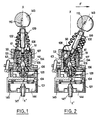
- the manipulator essentially comprises a housing 101 on which is articulated an operating lever 102 which can be moved apart by transverse thrust F (Figure 2) of a reference position xx '( Figure 1), called neutral, corresponding to the axis of the housing 101, the lever 102 being resiliently biased towards this neutral position.
- the lever 102 controls the position of at least one movable influence member 103 which is associated with at least one sensor 104 fixed to the housing 101 to deliver an electrical signal depending on the position of the lever 102.
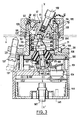
- the operating lever 102 is articulated on the housing 101 by means of a complex articulation 51 comprising a ball joint 50 having a hemispherical head 61 which cooperates with a spherical bearing surface 64 of a cap 59 of a barrel 134, open to his part upper for the passage of the lever 102.
- the latter is angularly integral with the ball joint 50 whose axial extension forms a cavity 62 in which is engaged the spherical head 63 of an auxiliary shaft 52 housed in the housing 101 and which is itself even mounted on a ball joint 105 which carries the movable member (s) of influence 103.
- the ball joint 105 is elastically urged towards an annular bearing surface 106 of the housing 101 and its outer spherical surface bears on the spherical cavity of this bearing, the contact being concentric with center O ( Figure 3).
- this type of manipulator can be advantageously used in applications where it is desired that the amplitude of the signals delivered is the image of the displacements of greater amplitude of the lever.
- the ball 105 carries (FIG. 8), on the side opposite the fixed bearing 106, a ring 122 coaxial with the shaft 52 from which a number of radial ribs 123 emerge.
- the ring 122 and the ribs 123 are engaged respectively in a central circular opening 124 (FIG. 9) and in radial slots 125 formed in an elastic membrane 126 on which the ball 105 is supported.
- This membrane 126 forms tongues 127 which are selectively engaged by the base of the ball 105 according to the orientation of the lever 102. In the neutral position of the latter, each sector 128 of the base of the ball 105 between two ribs 123 consecutive is pressed equally against a corresponding tongue 127 of the membrane 126.
- the periphery of the membrane 126 which has (see FIG. 9) centering notches 129 engaged in lugs 131 of the housing 101, is clamped between an annular shoulder of the housing 101 and the base of the annular surface 106. The fixing of the assembly is ensured by screws 33 engaged in tapped recesses of the pins 131 of the housing 101.
- the threaded lower end 2b of the shaft 52 which passes through an opening 5a of the ball joint 105, opens beyond the ring 122 and receives a nut 140 which secures and centers the influence members 103 by tightening those -this against the ring 122 of the ball joint 105.
- the ring 122 has two pins 22a, 22b ( Figure 8) for fixing the orientation of the members 103 by entering a centering hole 30 ( Figure 3) thereof.
- the electronic circuits to which the position sensors 104 influenced by the movable members 103 belong are disposed in a chamber 144 of the housing 101 closed by a bottom 145 and separated from the ball joint 105 by a partition 46 made of electrically insulating material.
- the end part of the barrel 134 which surmounts the housing 101 is threaded and receives a clamping ring 135 which contributes to the fixing of the manipulator on a plate A (FIG. 3), in opposition to setting screws 137 carried by a flange 38, it - even supported on the shoulder of the housing 101.
- the upper end of the barrel 134 is closed by a flexible cylindrical bellows 139 for sealing, clamped at its base by the threaded ring 135 and at its top by the button 143 screwed onto the threaded end 110 of the lever 102.
- Means are provided opposing the angular displacements of the lever 102 for an elastic reaction differentiated according to the orientation which is given to it. imposed in relation to its neutral position.
- These means include two associated cams 107 and 108 whose active surfaces 109 and 111 have profiles arranged to provide a significant variation in the force required to move the lever 102 from its neutral position according to the orientation that the operator wants to give it. . Details of the profiles of these cams will be provided below with reference to FIGS. 4 and 5.
- the angularly fixed cam 107 is coaxial with the neutral position XX ′ and the other 108, angularly orientable as a function of the position of the lever 102, is coaxial with the latter.
- the angularly fixed cam 107 (FIG. 3) is carried by a sliding plunger 53 surrounding the auxiliary shaft 52 and movable coaxially in the neutral position X-X 'of the lever 102.
- the pusher 53 is hollow and has a cylindrical skirt 55 which slides inside the chamber 134b of the barrel 134, the rotation of the pusher 53 around the axis XX 'being prevented by a longitudinal rib 71 of the skirt 55 in engagement with a groove 72 in the chamber 134b (see Figures 3 and 5).
- the skirt 55 which surrounds the auxiliary shaft 52 and the return spring 112 has at its upper part a crown 56 whose wall 109 opposite the ball 105 constitutes the active surface of the cam 107.
- the periphery of the ball joint 50 is wavy and constitutes the active surface 111 of the cam 108.
- the active surfaces 109, 111 of the cams 107, 108 are resiliently biased towards one another by the helical spring 112 which is supported between a shoulder 65 of the annular surface 106 and the crown 56 of the pusher 53.
- the thrust of the spring 112 also ensures the support of the hemispherical head 61 against the surface 64.
- FIGS. 4 and 5 and respectively 6 and 7 illustrate two alternative embodiments of the pusher 53 carrying the cam 107 and of the ball joint 50 carrying the cam 108 integral in rotation with the operating lever 102.
- the cams 107, 108 of the variant of FIGS. 6 and 7 have a continuous wavy contour having a succession of inflection points, while those of FIGS. 4 and 5 have a discontinuous wavy contour respectively forming a succession of edges 82 and of hollow 83 (see Figure 5) or curved parts 74 (see Figure 4).
- the first pair corresponds to two orthogonal planes P, Q and the second pair, non-privileged, corresponds to the R and S orientations of lever 102 in the bisector plans of the previous ones.
- the planes P and Q correspond to the hollow parts of the profile 109 of the cam 107 and the planes R and S to the vertices of this same profile.
- FIG. 10 illustrates an alternative embodiment of the manipulators described respectively with reference to FIGS. 1 to 9.
- the members having similar functions bear the same references assigned an index a.
- the auxiliary shaft 52a is connected to the housing 101a by means of a pseudo-articulation constituted by an elastic mass 75, for example of elastomeric material, the periphery 76 of which adheres to the lower surface 77 of an annular bearing surface 78 integral of housing 101a.
- the end of the auxiliary shaft 52a opposite the operating button 143a carries a sleeve 79 which is immobilized by overmolding in the elastomer mass 75.
- This sleeve 79 carries the organs 103a of influence of the position sensors belonging to the electronic circuits of the manipulator (not shown).
- the spring 112a for biasing the cams 107a, 108a towards one another is mounted to bear on a washer 81 which is supported by a shoulder 84 of the annular bearing surface 78 of the housing 101a.
- a pseudoarticulation is described in FR - A - 2,559,305 already cited.
- the elastic mass 75 replaces economically but without allowing angular guidance, the articulation ball 105 supported by the elastic membrane 126 of the previous embodiment.
Landscapes
- Physics & Mathematics (AREA)
- General Physics & Mathematics (AREA)
- Engineering & Computer Science (AREA)
- Automation & Control Theory (AREA)
- Manipulator (AREA)
- Mechanical Control Devices (AREA)
- Switches With Compound Operations (AREA)
- Position Input By Displaying (AREA)
Applications Claiming Priority (2)
| Application Number | Priority Date | Filing Date | Title |
|---|---|---|---|
| FR8607289A FR2599185B1 (fr) | 1986-05-22 | 1986-05-22 | Manipulateur analogique a orientations privilegiees |
| FR8607289 | 1986-05-22 |
Publications (2)
| Publication Number | Publication Date |
|---|---|
| EP0246968A1 EP0246968A1 (fr) | 1987-11-25 |
| EP0246968B1 true EP0246968B1 (fr) | 1991-08-07 |
Family
ID=9335477
Family Applications (1)
| Application Number | Title | Priority Date | Filing Date |
|---|---|---|---|
| EP87401126A Expired - Lifetime EP0246968B1 (fr) | 1986-05-22 | 1987-05-20 | Manipulateur analogique à orientations privilégiées |
Country Status (8)
| Country | Link |
|---|---|
| US (1) | US4784008A (https=) |
| EP (1) | EP0246968B1 (https=) |
| CH (1) | CH674101A5 (https=) |
| DE (1) | DE3771928D1 (https=) |
| DK (1) | DK169800B1 (https=) |
| FR (2) | FR2599185B1 (https=) |
| GB (1) | GB2190987B (https=) |
| IT (1) | IT1206063B (https=) |
Families Citing this family (29)
| Publication number | Priority date | Publication date | Assignee | Title |
|---|---|---|---|---|
| WO1990009565A1 (en) * | 1989-02-14 | 1990-08-23 | Michael Alan Stern | Opto-electrical joystick switch |
| DE4017696A1 (de) * | 1990-06-01 | 1991-12-05 | Bosch Gmbh Robert | Steuergeber |
| US5068498A (en) * | 1990-08-14 | 1991-11-26 | Wico Distribution Corp. | Joystick for mounting on dual-width panels |
| US5140313A (en) * | 1991-01-17 | 1992-08-18 | O Che Wen | Joy stick assembly |
| DE4127730A1 (de) * | 1991-08-22 | 1993-03-04 | Ford Werke Ag | Schalthebellagerung fuer getriebe von kraftfahrzeugen |
| FR2689262B1 (fr) * | 1992-03-27 | 1994-05-06 | Telemecanique | Appareil de commande a levier. |
| US5313853A (en) * | 1992-12-14 | 1994-05-24 | Grand Haven Stamped Products Company, Div. Of Jsj Corporation | Flat spring biased shifter |
| WO1994019735A1 (de) * | 1993-02-20 | 1994-09-01 | Nbb Nachrichtentechnik Gmbh & Co. Kg | Handsteuergerät mit einem steuerknüppel |
| US5619021A (en) * | 1993-11-19 | 1997-04-08 | Sumitomo Wiring Systems, Ltd. | Lever switch device, method for activating switches in a lever switch device, and method for outputting data signals |
| US5691517A (en) * | 1993-11-19 | 1997-11-25 | Sumitomo Wiring Systems, Ltd. | Multidirectional lever switch device |
| US5773773A (en) * | 1993-11-22 | 1998-06-30 | Chrysler Corporation | Joystick with detent mechanism for tactile feedback centering |
| US5493931A (en) * | 1994-02-14 | 1996-02-27 | Grand Haven Stamped Products Company, Div. Of Jsj Corp. | Vehicle shifter |
| US5592856A (en) * | 1995-02-15 | 1997-01-14 | New Venture Gear, Inc. | Self-centering shifter assembly |
| US5744765A (en) * | 1995-06-19 | 1998-04-28 | Sumitomo Wiring Systems, Ltd. | Lever switch with support walls for supporting movable contact points and method of detecting an operating direction of a lever switch |
| US5675309A (en) * | 1995-06-29 | 1997-10-07 | Devolpi Dean | Curved disc joystick pointing device |
| US6082212A (en) * | 1997-07-25 | 2000-07-04 | Crown Equipment Corporation | Multi-function control handle |
| JP3694392B2 (ja) * | 1997-08-22 | 2005-09-14 | アルプス電気株式会社 | 複合操作型電気部品 |
| JP3746374B2 (ja) * | 1998-05-26 | 2006-02-15 | アルプス電気株式会社 | 多方向入力装置 |
| GB2366924B (en) * | 2000-09-13 | 2002-09-18 | Unique Product & Design Co Ltd | Electric carrier with a motor controlled by a relative positional mechanism |
| JP2002312047A (ja) * | 2001-04-16 | 2002-10-25 | Alps Electric Co Ltd | 手動入力装置 |
| FR2857762A1 (fr) * | 2003-07-18 | 2005-01-21 | Daniel Bignon | Mecanisme de commande par cable comportant un organe elastiquement deformable d'assistance a la manoeuvre du cable |
| DE602004010763T2 (de) * | 2003-10-14 | 2008-04-30 | Alps Electric Co., Ltd. | Steuerknüppeleingabegerät |
| DE102005035526A1 (de) * | 2004-07-28 | 2006-03-23 | Marquardt Gmbh | Elektrischer Schalter |
| US9429978B2 (en) * | 2013-01-25 | 2016-08-30 | Woodward, Inc. | Passive control stick |
| JP6686498B2 (ja) * | 2015-08-31 | 2020-04-22 | オムロン株式会社 | スイッチ |
| EP3367205A1 (de) * | 2017-02-24 | 2018-08-29 | RAFI GmbH & Co. KG | Steuer-vorrichtung |
| US11921536B2 (en) * | 2022-01-26 | 2024-03-05 | Woodward, Inc. | Soft stop force gradient for control stick |
| GB202208912D0 (en) * | 2022-06-17 | 2022-08-10 | Dexter James | Modular joystick controller |
| WO2023242547A1 (en) * | 2022-06-17 | 2023-12-21 | Scorpion Joystick Ltd | Joystick |
Citations (2)
| Publication number | Priority date | Publication date | Assignee | Title |
|---|---|---|---|---|
| US3827313A (en) * | 1973-01-24 | 1974-08-06 | Square D Co | Miniaturized joystick and cam structure with push button switch operating means |
| EP0043809A2 (en) * | 1980-07-04 | 1982-01-13 | Hydrino Ab | Device in a multi-way lever |
Family Cites Families (11)
| Publication number | Priority date | Publication date | Assignee | Title |
|---|---|---|---|---|
| US2808476A (en) * | 1954-06-25 | 1957-10-01 | Gen Motors Corp | Electric switch |
| US3219782A (en) * | 1962-08-08 | 1965-11-23 | Cincinnati Milling Machine Co | Joystick control switch with electromagnetic detent |
| DE1268251B (de) * | 1966-07-09 | 1968-05-16 | Siemens Ag | Schaltgeraet mit einer schwenkbaren Schaltstange |
| CH531749A (de) * | 1971-05-14 | 1972-12-15 | Saab Scania Ab | Steuerhebelanordnung |
| US3731013A (en) * | 1972-01-07 | 1973-05-01 | C Nightengale | Switch control means |
| US3818154A (en) * | 1973-04-09 | 1974-06-18 | S Presentey | Joystick type controller for switches |
| DE7340888U (de) * | 1973-11-15 | 1974-02-21 | Maecker K Gmbh | Schwenkhebelschalter mit wenigstens zwei Schaltstellungen |
| GB2046022A (en) * | 1979-03-14 | 1980-11-05 | Shelton G G | Electric switches |
| SE443672B (sv) * | 1982-12-23 | 1986-03-03 | Akermans Verkstad Ab | Styrspakanordning |
| FR2559305B1 (fr) * | 1984-02-08 | 1986-10-17 | Telemecanique Electrique | Manipulateur analogique |
| DE3442287A1 (de) * | 1984-11-20 | 1986-05-22 | SWF Auto-Electric GmbH, 7120 Bietigheim-Bissingen | Elektischer schalter |
-
1986
- 1986-05-22 FR FR8607289A patent/FR2599185B1/fr not_active Expired
- 1986-05-22 FR FR868607290A patent/FR2599186B1/fr not_active Expired
-
1987
- 1987-05-15 GB GB8711476A patent/GB2190987B/en not_active Expired - Lifetime
- 1987-05-15 CH CH1877/87A patent/CH674101A5/fr not_active IP Right Cessation
- 1987-05-20 EP EP87401126A patent/EP0246968B1/fr not_active Expired - Lifetime
- 1987-05-20 DE DE8787401126T patent/DE3771928D1/de not_active Expired - Lifetime
- 1987-05-21 US US07/052,474 patent/US4784008A/en not_active Expired - Fee Related
- 1987-05-21 IT IT8747960A patent/IT1206063B/it active
- 1987-05-21 DK DK259187A patent/DK169800B1/da not_active IP Right Cessation
Patent Citations (2)
| Publication number | Priority date | Publication date | Assignee | Title |
|---|---|---|---|---|
| US3827313A (en) * | 1973-01-24 | 1974-08-06 | Square D Co | Miniaturized joystick and cam structure with push button switch operating means |
| EP0043809A2 (en) * | 1980-07-04 | 1982-01-13 | Hydrino Ab | Device in a multi-way lever |
Also Published As
| Publication number | Publication date |
|---|---|
| DE3771928D1 (de) | 1991-09-12 |
| DK259187D0 (da) | 1987-05-21 |
| FR2599186A2 (fr) | 1987-11-27 |
| EP0246968A1 (fr) | 1987-11-25 |
| DK169800B1 (da) | 1995-02-27 |
| US4784008A (en) | 1988-11-15 |
| FR2599185B1 (fr) | 1988-11-10 |
| GB8711476D0 (en) | 1987-06-17 |
| FR2599186B1 (fr) | 1988-11-25 |
| GB2190987A (en) | 1987-12-02 |
| IT1206063B (it) | 1989-04-14 |
| GB2190987B (en) | 1990-07-04 |
| IT8747960A0 (it) | 1987-05-21 |
| CH674101A5 (https=) | 1990-04-30 |
| DK259187A (da) | 1987-11-23 |
| FR2599185A1 (fr) | 1987-11-27 |
Similar Documents
| Publication | Publication Date | Title |
|---|---|---|
| EP0246968B1 (fr) | Manipulateur analogique à orientations privilégiées | |
| EP0103327B1 (fr) | Dispositif interrupteur à plusieurs voies, tel qu'une commande multidirectionnelle pour jeu électronique | |
| EP2204719B1 (fr) | Joystick à effet Hall, procédé de fabrication et manette correspondants | |
| EP0635858B1 (fr) | Manipulateur à actionnement multimode | |
| EP2033063B1 (fr) | Dispositif de commande electrique | |
| FR2954980A1 (fr) | Joystick a ressorts de compensation, procede de fabrication et manette correspondants. | |
| FR2913811A1 (fr) | Organe de commande multidirectionnel ergonomique | |
| WO2005106908A1 (fr) | Bouton rotatif pour circuit electrique | |
| EP0642075A1 (fr) | Procédé et dispositif pour la gestion des déplacements relatifs d'un curseur par rapport à l'image affichée sur un dispositif de visualisation | |
| EP0267078B1 (fr) | Ensemble de palier de rampe de détection de position pour un inverseur de poussée de turbosoufflante | |
| FR2957187A1 (fr) | Commutateur electrique a effet tactile a double action | |
| WO2019053066A1 (fr) | Dispositif de commande pour interface homme-machine à éléments électro-actifs | |
| EP1977304B1 (fr) | Perfectionnements aux peripheriques d'entree pour ordinateur ou similaire | |
| EP4127857B1 (fr) | Interface homme-machine | |
| EP0500000B1 (fr) | Elément de commande formant souris | |
| EP1416506A2 (fr) | Organe de commande à bouton de manipulation rotatif autour de plusieurs axes | |
| WO2000030136A1 (fr) | Detecteur de position avec mecanisme d'orientation | |
| EP2192604B1 (fr) | Dispositif d'entrée de données à sensation tactile améliorée | |
| EP1607268B1 (fr) | Système d'indexage mécanique, notamment pour commutateur électrique | |
| WO2002099825A1 (fr) | Dispositif de commande pour vehicule automobile destine notamment a piloter un ordinateur de bord | |
| EP0368754A1 (fr) | Dispositif de commutation électrique, commandable mécaniquement de façon réglable | |
| EP0225211A1 (fr) | Dispositif de sécurité de commande de marche arrière pour levier de vitesse cassé | |
| CA1291799C (fr) | Dispositif anti-inversion du mouvement relatif de deux organes, respectivement male et femelle, dont l'un est actionne manuellement | |
| FR2773877A1 (fr) | Transducteur comprenant un arbre de commande actionne a rotation, notamment sous forme de commutateur | |
| EP1047985A1 (fr) | Dispositif de telecommande, notamment manipulateur hydraulique |
Legal Events
| Date | Code | Title | Description |
|---|---|---|---|
| PUAI | Public reference made under article 153(3) epc to a published international application that has entered the european phase |
Free format text: ORIGINAL CODE: 0009012 |
|
| 17P | Request for examination filed |
Effective date: 19870523 |
|
| AK | Designated contracting states |
Kind code of ref document: A1 Designated state(s): CH DE LI NL SE |
|
| RBV | Designated contracting states (corrected) |
Designated state(s): DE NL SE |
|
| 17Q | First examination report despatched |
Effective date: 19900305 |
|
| GRAA | (expected) grant |
Free format text: ORIGINAL CODE: 0009210 |
|
| AK | Designated contracting states |
Kind code of ref document: B1 Designated state(s): DE NL SE |
|
| REF | Corresponds to: |
Ref document number: 3771928 Country of ref document: DE Date of ref document: 19910912 |
|
| PLBE | No opposition filed within time limit |
Free format text: ORIGINAL CODE: 0009261 |
|
| STAA | Information on the status of an ep patent application or granted ep patent |
Free format text: STATUS: NO OPPOSITION FILED WITHIN TIME LIMIT |
|
| 26N | No opposition filed | ||
| EAL | Se: european patent in force in sweden |
Ref document number: 87401126.5 |
|
| PGFP | Annual fee paid to national office [announced via postgrant information from national office to epo] |
Ref country code: NL Payment date: 19990416 Year of fee payment: 13 |
|
| PGFP | Annual fee paid to national office [announced via postgrant information from national office to epo] |
Ref country code: DE Payment date: 19990508 Year of fee payment: 13 |
|
| PGFP | Annual fee paid to national office [announced via postgrant information from national office to epo] |
Ref country code: SE Payment date: 19990512 Year of fee payment: 13 |
|
| PG25 | Lapsed in a contracting state [announced via postgrant information from national office to epo] |
Ref country code: SE Free format text: LAPSE BECAUSE OF NON-PAYMENT OF DUE FEES Effective date: 20000521 |
|
| PG25 | Lapsed in a contracting state [announced via postgrant information from national office to epo] |
Ref country code: NL Free format text: LAPSE BECAUSE OF NON-PAYMENT OF DUE FEES Effective date: 20001201 |
|
| EUG | Se: european patent has lapsed |
Ref document number: 87401126.5 |
|
| NLV4 | Nl: lapsed or anulled due to non-payment of the annual fee |
Effective date: 20001201 |
|
| PG25 | Lapsed in a contracting state [announced via postgrant information from national office to epo] |
Ref country code: DE Free format text: LAPSE BECAUSE OF NON-PAYMENT OF DUE FEES Effective date: 20010301 |