EP0246772A1 - Système de suspension pour véhicule à moteur - Google Patents
Système de suspension pour véhicule à moteur Download PDFInfo
- Publication number
- EP0246772A1 EP0246772A1 EP87303863A EP87303863A EP0246772A1 EP 0246772 A1 EP0246772 A1 EP 0246772A1 EP 87303863 A EP87303863 A EP 87303863A EP 87303863 A EP87303863 A EP 87303863A EP 0246772 A1 EP0246772 A1 EP 0246772A1
- Authority
- EP
- European Patent Office
- Prior art keywords
- suspension system
- damping
- setting
- settings
- sprung mass
- Prior art date
- Legal status (The legal status is an assumption and is not a legal conclusion. Google has not performed a legal analysis and makes no representation as to the accuracy of the status listed.)
- Granted
Links
Images


Classifications
-
- B—PERFORMING OPERATIONS; TRANSPORTING
- B60—VEHICLES IN GENERAL
- B60G—VEHICLE SUSPENSION ARRANGEMENTS
- B60G17/00—Resilient suspensions having means for adjusting the spring or vibration-damper characteristics, for regulating the distance between a supporting surface and a sprung part of vehicle or for locking suspension during use to meet varying vehicular or surface conditions, e.g. due to speed or load
- B60G17/015—Resilient suspensions having means for adjusting the spring or vibration-damper characteristics, for regulating the distance between a supporting surface and a sprung part of vehicle or for locking suspension during use to meet varying vehicular or surface conditions, e.g. due to speed or load the regulating means comprising electric or electronic elements
- B60G17/018—Resilient suspensions having means for adjusting the spring or vibration-damper characteristics, for regulating the distance between a supporting surface and a sprung part of vehicle or for locking suspension during use to meet varying vehicular or surface conditions, e.g. due to speed or load the regulating means comprising electric or electronic elements characterised by the use of a specific signal treatment or control method
-
- F—MECHANICAL ENGINEERING; LIGHTING; HEATING; WEAPONS; BLASTING
- F16—ENGINEERING ELEMENTS AND UNITS; GENERAL MEASURES FOR PRODUCING AND MAINTAINING EFFECTIVE FUNCTIONING OF MACHINES OR INSTALLATIONS; THERMAL INSULATION IN GENERAL
- F16F—SPRINGS; SHOCK-ABSORBERS; MEANS FOR DAMPING VIBRATION
- F16F9/00—Springs, vibration-dampers, shock-absorbers, or similarly-constructed movement-dampers using a fluid or the equivalent as damping medium
- F16F9/06—Springs, vibration-dampers, shock-absorbers, or similarly-constructed movement-dampers using a fluid or the equivalent as damping medium using both gas and liquid
- F16F9/08—Springs, vibration-dampers, shock-absorbers, or similarly-constructed movement-dampers using a fluid or the equivalent as damping medium using both gas and liquid where gas is in a chamber with a flexible wall
- F16F9/088—Springs, vibration-dampers, shock-absorbers, or similarly-constructed movement-dampers using a fluid or the equivalent as damping medium using both gas and liquid where gas is in a chamber with a flexible wall comprising a gas spring with a flexible wall provided within the cylinder on the piston rod of a monotubular damper or within the inner tube of a bitubular damper
-
- B—PERFORMING OPERATIONS; TRANSPORTING
- B60—VEHICLES IN GENERAL
- B60G—VEHICLE SUSPENSION ARRANGEMENTS
- B60G2400/00—Indexing codes relating to detected, measured or calculated conditions or factors
- B60G2400/10—Acceleration; Deceleration
- B60G2400/102—Acceleration; Deceleration vertical
-
- B—PERFORMING OPERATIONS; TRANSPORTING
- B60—VEHICLES IN GENERAL
- B60G—VEHICLE SUSPENSION ARRANGEMENTS
- B60G2400/00—Indexing codes relating to detected, measured or calculated conditions or factors
- B60G2400/10—Acceleration; Deceleration
- B60G2400/106—Acceleration; Deceleration longitudinal with regard to vehicle, e.g. braking
-
- B—PERFORMING OPERATIONS; TRANSPORTING
- B60—VEHICLES IN GENERAL
- B60G—VEHICLE SUSPENSION ARRANGEMENTS
- B60G2400/00—Indexing codes relating to detected, measured or calculated conditions or factors
- B60G2400/20—Speed
- B60G2400/204—Vehicle speed
-
- B—PERFORMING OPERATIONS; TRANSPORTING
- B60—VEHICLES IN GENERAL
- B60G—VEHICLE SUSPENSION ARRANGEMENTS
- B60G2400/00—Indexing codes relating to detected, measured or calculated conditions or factors
- B60G2400/20—Speed
- B60G2400/206—Body oscillation speed; Body vibration frequency
-
- B—PERFORMING OPERATIONS; TRANSPORTING
- B60—VEHICLES IN GENERAL
- B60G—VEHICLE SUSPENSION ARRANGEMENTS
- B60G2400/00—Indexing codes relating to detected, measured or calculated conditions or factors
- B60G2400/30—Propulsion unit conditions
- B60G2400/33—Throttle position
-
- B—PERFORMING OPERATIONS; TRANSPORTING
- B60—VEHICLES IN GENERAL
- B60G—VEHICLE SUSPENSION ARRANGEMENTS
- B60G2400/00—Indexing codes relating to detected, measured or calculated conditions or factors
- B60G2400/40—Steering conditions
-
- B—PERFORMING OPERATIONS; TRANSPORTING
- B60—VEHICLES IN GENERAL
- B60G—VEHICLE SUSPENSION ARRANGEMENTS
- B60G2401/00—Indexing codes relating to the type of sensors based on the principle of their operation
- B60G2401/10—Piezoelectric elements
-
- B—PERFORMING OPERATIONS; TRANSPORTING
- B60—VEHICLES IN GENERAL
- B60G—VEHICLE SUSPENSION ARRANGEMENTS
- B60G2500/00—Indexing codes relating to the regulated action or device
- B60G2500/10—Damping action or damper
- B60G2500/102—Damping action or damper stepwise
-
- B—PERFORMING OPERATIONS; TRANSPORTING
- B60—VEHICLES IN GENERAL
- B60G—VEHICLE SUSPENSION ARRANGEMENTS
- B60G2600/00—Indexing codes relating to particular elements, systems or processes used on suspension systems or suspension control systems
- B60G2600/02—Retarders, delaying means, dead zones, threshold values, cut-off frequency, timer interruption
-
- B—PERFORMING OPERATIONS; TRANSPORTING
- B60—VEHICLES IN GENERAL
- B60G—VEHICLE SUSPENSION ARRANGEMENTS
- B60G2600/00—Indexing codes relating to particular elements, systems or processes used on suspension systems or suspension control systems
- B60G2600/14—Differentiating means, i.e. differential control
-
- B—PERFORMING OPERATIONS; TRANSPORTING
- B60—VEHICLES IN GENERAL
- B60G—VEHICLE SUSPENSION ARRANGEMENTS
- B60G2600/00—Indexing codes relating to particular elements, systems or processes used on suspension systems or suspension control systems
- B60G2600/22—Magnetic elements
- B60G2600/26—Electromagnets; Solenoids
-
- B—PERFORMING OPERATIONS; TRANSPORTING
- B60—VEHICLES IN GENERAL
- B60G—VEHICLE SUSPENSION ARRANGEMENTS
- B60G2600/00—Indexing codes relating to particular elements, systems or processes used on suspension systems or suspension control systems
- B60G2600/60—Signal noise suppression; Electronic filtering means
- B60G2600/602—Signal noise suppression; Electronic filtering means high pass
-
- B—PERFORMING OPERATIONS; TRANSPORTING
- B60—VEHICLES IN GENERAL
- B60G—VEHICLE SUSPENSION ARRANGEMENTS
- B60G2600/00—Indexing codes relating to particular elements, systems or processes used on suspension systems or suspension control systems
- B60G2600/60—Signal noise suppression; Electronic filtering means
- B60G2600/604—Signal noise suppression; Electronic filtering means low pass
-
- B—PERFORMING OPERATIONS; TRANSPORTING
- B60—VEHICLES IN GENERAL
- B60G—VEHICLE SUSPENSION ARRANGEMENTS
- B60G2800/00—Indexing codes relating to the type of movement or to the condition of the vehicle and to the end result to be achieved by the control action
- B60G2800/01—Attitude or posture control
- B60G2800/012—Rolling condition
-
- B—PERFORMING OPERATIONS; TRANSPORTING
- B60—VEHICLES IN GENERAL
- B60G—VEHICLE SUSPENSION ARRANGEMENTS
- B60G2800/00—Indexing codes relating to the type of movement or to the condition of the vehicle and to the end result to be achieved by the control action
- B60G2800/01—Attitude or posture control
- B60G2800/014—Pitch; Nose dive
-
- B—PERFORMING OPERATIONS; TRANSPORTING
- B60—VEHICLES IN GENERAL
- B60G—VEHICLE SUSPENSION ARRANGEMENTS
- B60G2800/00—Indexing codes relating to the type of movement or to the condition of the vehicle and to the end result to be achieved by the control action
- B60G2800/22—Braking, stopping
Definitions
- This invention relates to a suspension system for a motor vehicle.
- the suspension of a vehicle has traditionally consisted of a hub and wheel supported by a rubber tyre with a relatively soft spring supporting the body above the hub.
- the mass supported by the spring is considered “sprung” and the mass not supported by the spring, but supported by the tyre is considered “unsprung”.
- the purpose of the spring is to isolate the body from road undulations.
- the first of these, the resonance of the sprung mass on the spring manifests itself in a four-wheel car as the "primary ride” resonances and these are usually described by the terms “bounce”, “heave”, “pitch” and “roll”.
- the frequencies of these resonances typically occur in the range 0.8 - 4.0 Hz.
- the second resonance, that of the unsprung mass on the spring stiffness offered by the tyre is called 'wheel-hop' and typically occurs at frequencies in the range 10 - 15 Hz.
- the traditional suspension described above will isolate the body, or sprung mass, from road inputs above the primary ride frequencies, with the exception that, at wheel hop frequency, the resonance enhances transmission to the body of any road inputs of that frequency. Resonance at any of the primary ride frequencies also enhances transmission giving larger body motions than would occur if the suspension were infinitely rigid.
- This system has the disadvantage that it is relatively complex and hence expensive to produce.
- a suspension system for a vehicle comprising: at least one resilient means connecting a sprung mass and an unsprung mass; at least one damping means switchable between a relatively soft setting and a relatively stiff setting for damping relative motion between the sprung mass and the unsprung mass; a sensor means for sensing motion of the sprung mass; filter means for filtering a signal from the sensor to select a predetermined band width of frequencies of motion of the sprung mass; and control means for switching the damping means between the relatively soft and relatively stiff settings in response to a signal received from the sensor means characterised in that each of the damping means has a relatively stiff and soft setting in both the bump and rebound directions and that the damping means are switched to the relatively stiff setting when the motion of the sprung mass in either direction exceeds a predetermined level set for that direction of motion.
- the pre-determined level may be a level of vertical acceleration.
- the shock absorbers may be switched to their relatively stiffer setting only while the pre-determined level is exceeded.
- damping settings may be switched to the relatively stiff setting at the first peak vertical acceleration of the sprung mass following the pre-determined level being exceeded.
- the damping effect in each direction may be restored to the relatively soft settings at the first peak in acceleration of the sprung mass which dores not exceed the pre-determined level.
- damping settings may be restored to the relatively soft setting.
- the pre-determined level may be a level of vertical velocity of the sprung mass, in which case the damper settings may be switched to the rleatively stiff setting on the first occasion that the direction of motion changes after a pre-determined level of vertical velocity has been exceeded and may be restored to the relatively soft setting on the first occasion when the direction of motion of the sprung mass changes following a peak in velocity which does not exceed the pre-determined level.
- the suspension system may have in addition to the relatively stiff and soft settings a further relatively harder setting the control means being arranged to switch the damping means between the relatively stiff and soft settings below a pre-determined vehicle speed and between the relatively stiff and harder settings above the pre-determined vehicle speed.
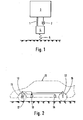
- Figure 1 is a schematic diagram of a conventional suspension system as described above in which a spring 1 and damper, 2 connect a sprung mass 3 and an unsprung mass 4.
- a spring 5 is also shown to represent the spring provided by the tyre between the'ground and the unsprung mass 4.
- the suspension system according to the first embodiment of the invention seeks to compromise between the requirement to provide low damping, to prevent the transmission of vibration at wheel-hop', and the requirement to provide high damping to prevent 'float' at primary ride frequency.
- a motor vehicle having a body 13; a number of road wheels 15 and a suspension system to provide a damped resilient connection between the wheels 15 and the body 13 forming a sprung mass.
- the suspension system comprises a number of dampers or shock absorbers 12, a number of road springs (not shown) an accelerometer 16 connected to the body 13, a microprocessor based control system 18, and a vehicle forward speed transducer 17.
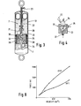
- Each of the shock absorbers 12 has a casing 26 in which is slidably supported a piston 25 adapted for connection to part of the body 13 of the vehicle by means of a tubular rod 22.
- the piston 25 includes a number of bypass passages 28 and first and second solenoid valves 21,24.
- the first solenoid valve 21 closes when energised to increase the stiffness of the shock absorber in the bump direction of travel and the second solenoid valve 24 closes when energised to increase the stiffness of the shock absorber in the rebound direction of travel.
- the first and second solenoid valves 21 and 24 are connected to the control system 18 by means of a multi-cored wire 23 which passes along the bore of the tubular rod 22.
- the position that the sphere 33 adopts therefore determines the damping effect of the shock absorber 12, if the orifice 32 is closed off by the sphere 33 then fluid 7 can only be transferred from one side of the piston 25 to the other through the bypass passages 28 thereby greatly increasing the damping effect of the shock absorber. If the solenoid is not energised then the sphere 33 is moved back by the flow of the fluid 7 through the orifice 32 and the restriction to flow is that primarily cause by the orifice 32 itself and the damping effect is thus reduced.
- the other solenoid valve operates in the same manner as that previously described but being mounted in the piston 25 in the opposite sense so that it controls the flow of fluid 7 during rebound motion of the body 13.
- the piston 25 may of course be provided with conventional valves in addition to the solenoid valves mentioned to provide different damping effects in opposite directions when the solenoid valve for that direction of motion is closed.
- each of the shock absorbers 12 is entirely . conventional in construction and needs no further description.
- the accelerometer 16 in the form of a piezoelectric accelerometers measures the vertical acceleration of the vehicle body 13, and sends a signal indicative of this movement to the control system 18 to act as the primary control parameter for the suspension system.
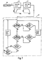
- the control system 18 comprises a first filter 40 to filter out frequencies below 0.3 Hz, a second filter 41 to filter out frequencies above 4.5 Hz, a central processor unit including a pre-programmed RAM unit 45A,45B, a pre-programmed ROM unit 46 and a pair of power amplifiers 43A,43B.
- a signal from the accelerometer 16 is transmitted to the filters 40,41 for signal conditioning.
- the filtered signal which represents acceleration of-the body 13 only in the range of primary ride frequency is the sent to the central proccessor unit 42.
- the signal is converted into a digital signal and then is read in as the primary data for the program stored in the RAM part of the central proccessor 42.
- the program reads the data from the accelerometer 16 and compares it with predetermined threshold levels of vertical acceleration for the bump and rebound directions of motion which are stored in digital form in the ROM 46.
- a control signal is sent to the amplifiers 43A,43B by the respective RAM 45A.
- the signal received by the amplifiers 43A,43B causes them to be activated and supply an energising signal to each of the solenoid valves 21,24.
- the energisation of the valves 21,24 will cause the damping of the body 13 to be increased from its normally relatively soft setting to a relatively stiff setting. The damping will stay at this relatively stiff setting until the central proccessor unit 42 senses that the level.
- a control signal is sent from RAM 45B to the amplifiers 43A,43B.
- the signal received by the. amplifier 43A,43B causes them to be activated and supply an energising signal to each of the solenoid valves 21,24.
- the energisation of the valves 21,24 will cause the damping of the body 13 to be increased from its normally relatively soft setting to a relatively stiff setting.
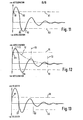
- the damping will stay at this relatively stiff setting until the central proccessor unit 42 senses that the level of acceleration in that direction has fallen below the pre-determined threshold level X2 such as at point R2 at which time the control signal to the amplifiers 43A,43B and the energising signal to the solenoid valves 21,24 will be switched off restoring the shock absorbers to their normally relatively soft setting.
- the pre-determined threshold level X2 such as at point R2 at which time the control signal to the amplifiers 43A,43B and the energising signal to the solenoid valves 21,24 will be switched off restoring the shock absorbers to their normally relatively soft setting.
- the pre-determined level X1 of vertical acceleration in the bump direction is set at a higher level than the pre-determined level - X2 for the rebound direction.
- the level X1 is set at..1.5 to 3.0 times that of level X2.
- Figure 8 illustrates typical characteristics of the soft and stiff settings of the shock absorbers 12.
- the vehicle is thus controlled to within set limits of vertical acceleration within the limited frequency range related to the body primary ride frequency by increasing the damping only under these clearly defined conditions.
- the softer damping can then be used at all other times to reduce high frequency input transmission to the sprung mass.
- the system is able to respond very quickly whenever the acceleration thresholds are exceeded due to the rapid response times of the solenoid valves 21,24 used within the shock absorbers 12.
- a response time of 10msec can be achieved with this arrangement which means that the shock absorbers 12 are quite capable of being switched into and out of the stiffer setting within one cycle of the motion of the vehicle body.
- the shock absorbers 12 can be otherwise conventional so there is no difficulty in arranging different levels of damping to be applied in the bump and rebound directions.
- a time delay TD is therefore provided as part of the control program, if the time delay TD is exceeded then the shock absorbers 12 are restored to their relatively soft setting.
- the acceleration signal from the accelerometer 16 is integrated to provide a signal indicative of vertical velocity of the body 13 which is then compared to pre-determined threshold levels UL,LL of velocity. If the vertical velocity of the body exceeds one of the pre-determined threshold levels UL, LL such as at point VI then the shock absorbers 12 are switched from their relatively soft setting to their relatively stiff setting on the next occasion when the direction of motion changes, that is to say when the velocity is zero, such as at point S1. The shock absorbers 12 will remain in this relatively stiff setting until the first occasion, following a peak in velocity that does not exceed one of the levels UL, LL, when the direction of motion changes such as at point S2.
- the integration of the signal from the accelerometer 16 may be done electronically by providing an integrator unit 29 as shown on Figures 9 and 10 or it can be done mathematically as part of the control system program.
- the signal from the forward speed transducer 17 for example may be used to alter the pre-determined threshold levels so that as the forward speed of the vehicle increases the threshold levels of vertical acceleration or velocity are reduced thereby taking into account the increasing dynamic effects on the vehicle.
- the system may be provided with shock absorbers having more than two settings.
- the shock absorber has a third solenoid valve operable to change the damping effect in the bump direction from the relatively stiff setting to a relatively hard setting when actuated and a fourth solenoid valve operable to change the damping effect in the rebound direction from the relatively stiff setting to the relatively hard setting when actuated.
- a signal indicative of vehicle forward. speed is supplied by the forward speed transducer 17 to the central processor 42 and is used to determine which of the settings is most appropriate. For example the shock absorbers are switched between the relatively soft setting and the relatively stiff setting at low speeds and between the relatively stiff setting and the relatively hard setting at higher speeds.
- the system may also be extended to provide individual control at each corner of the vehicle body by the provision of an accelerometer at each corner above the adjacent wheel.
- an accelerometer at each corner above the adjacent wheel.
- ride thresholds as described above, but also roll and pitch control with their. own discrete threshold levels and frequency filtering can be provided. This can apply to roll and pitch movements induced by ride motion or those esulting from braking, acceleration or steering manoeuvers.
- suitable sensors are provided in the braking, throttle and steering systems to sense movements therein and particularly the rate of change of movement.
- the relative movement between the wheel and the vehicle body may be sensed by displacement transducers, accelerometers or any other means, and the initiation of stiffer damping prevented when the wheel and body are moving in the same direction.
Landscapes
- Engineering & Computer Science (AREA)
- Mechanical Engineering (AREA)
- General Engineering & Computer Science (AREA)
- Vehicle Body Suspensions (AREA)
Applications Claiming Priority (2)
| Application Number | Priority Date | Filing Date | Title |
|---|---|---|---|
| GB8610842 | 1986-05-02 | ||
| GB868610842A GB8610842D0 (en) | 1986-05-02 | 1986-05-02 | Suspension system |
Publications (2)
| Publication Number | Publication Date |
|---|---|
| EP0246772A1 true EP0246772A1 (fr) | 1987-11-25 |
| EP0246772B1 EP0246772B1 (fr) | 1990-08-22 |
Family
ID=10597286
Family Applications (1)
| Application Number | Title | Priority Date | Filing Date |
|---|---|---|---|
| EP87303863A Expired EP0246772B1 (fr) | 1986-05-02 | 1987-04-30 | Système de suspension pour véhicule à moteur |
Country Status (4)
| Country | Link |
|---|---|
| US (1) | US4765648A (fr) |
| EP (1) | EP0246772B1 (fr) |
| DE (1) | DE3764399D1 (fr) |
| GB (1) | GB8610842D0 (fr) |
Cited By (19)
| Publication number | Priority date | Publication date | Assignee | Title |
|---|---|---|---|---|
| FR2629395A1 (fr) * | 1988-03-29 | 1989-10-06 | Boge Ag | Dispositif pour la commande assistee par ordinateur d'amortisseurs d'une suspension de vehicule en fonction de l'etat de la route |
| EP0341883A2 (fr) * | 1988-05-09 | 1989-11-15 | Lord Corporation | Méthode et dispositif de commande hybride analogue numérique pour le calcul de la vitesse absolue dans un système de suspension active |
| DE4017255A1 (de) * | 1989-05-29 | 1990-12-06 | Mitsubishi Electric Corp | Steuervorrichtung fuer eine trageinheit |
| DE4017256A1 (de) * | 1989-05-29 | 1990-12-06 | Mitsubishi Electric Corp | Steuervorrichtung fuer eine trageinheit |
| DE4017254A1 (de) * | 1989-05-29 | 1990-12-06 | Mitsubishi Electric Corp | Steuervorrichtung fuer eine trageinheit |
| WO1990014970A1 (fr) * | 1989-06-08 | 1990-12-13 | Robert Bosch Gmbh | Procede et dispositif pour amortir des sequences de mouvement |
| GB2234212A (en) * | 1989-05-31 | 1991-01-30 | Mitsubishi Electric Corp | Control of damping in a vehicle suspension |
| GB2236083A (en) * | 1989-09-04 | 1991-03-27 | Nissan Motor | Vehicle suspension control system with sensor resonance compensation |
| EP0426338A1 (fr) * | 1989-11-02 | 1991-05-08 | General Motors Corporation | Dispositif de suspension de véhicule |
| EP0545687A2 (fr) * | 1991-12-06 | 1993-06-09 | Kayaba Kogyo Kabushiki Kaisha | Système de suspension |
| EP0556070A2 (fr) * | 1992-02-14 | 1993-08-18 | Mitsubishi Jidosha Kogyo Kabushiki Kaisha | Méthode de détermination de l'état de la surface de la route et dispositif de commande de suspension |
| GB2273473A (en) * | 1992-12-03 | 1994-06-22 | Bosch Gmbh Robert | System for vehicle suspension control and/or regulation |
| GB2282784A (en) * | 1993-10-08 | 1995-04-19 | Acg France | Vehicle suspension system |
| DE4042452C2 (de) * | 1989-05-29 | 1996-03-07 | Mitsubishi Electric Corp | Steuervorrichtung für eine Fahrzeugaufhängung |
| WO1996007293A1 (fr) * | 1994-08-31 | 1996-03-07 | Blaupunkt-Werke Gmbh | Dispositif servant a reguler l'intensite sonore d'un autoradio en fonction du niveau sonore du vehicule |
| DE4042453C2 (de) * | 1989-05-29 | 1996-03-07 | Mitsubishi Electric Corp | Steuervorrichtung für eine Fahrzeugaufhängung |
| WO2011032560A1 (fr) | 2009-09-15 | 2011-03-24 | Ecomove Aps | Moyen de transport et véhicule |
| US8000480B2 (en) | 2003-06-17 | 2011-08-16 | Mollon Eric L | Automotive audio system adapted for roadway conditions |
| EP4046833A1 (fr) * | 2021-02-23 | 2022-08-24 | Fox Factory, Inc. | Véhicule et capteur de bosse |
Families Citing this family (61)
| Publication number | Priority date | Publication date | Assignee | Title |
|---|---|---|---|---|
| US4869444A (en) * | 1986-09-30 | 1989-09-26 | The Boeing Company | Adjustable two-stage aircraft landing gear system |
| DE3738284A1 (de) * | 1986-12-09 | 1988-06-30 | Bosch Gmbh Robert | Vorrichtung zur aktiven fahrwerkregelung bei kraftfahrzeugen |
| GB2205285B (en) * | 1987-04-24 | 1991-05-08 | Fuji Heavy Ind Ltd | Active suspension system of vehicle |
| JPH069846Y2 (ja) * | 1987-11-05 | 1994-03-16 | 三菱自動車工業株式会社 | アクテイブサスペンシヨン制御装置 |
| JPH0667684B2 (ja) * | 1988-06-16 | 1994-08-31 | 富士重工業株式会社 | 自動車用アクティブサスペンションの制御装置 |
| JP2752668B2 (ja) * | 1988-11-18 | 1998-05-18 | 株式会社ユニシアジェックス | サスペンションシステム |
| JPH082724B2 (ja) * | 1988-12-20 | 1996-01-17 | マツダ株式会社 | 車両のサスペンション装置 |
| FR2645981B1 (fr) * | 1989-04-17 | 1991-07-26 | Aerospatiale | Dispositif de commande en deplacement sans vibrations d'un element optique dans un interferometre stellaire et interferometre stellaire le comportant |
| JP3056748B2 (ja) * | 1989-05-15 | 2000-06-26 | 富士重工業株式会社 | 車両用アクテイブサスペンションの制御装置 |
| DE69029628T2 (de) * | 1989-09-11 | 1997-05-22 | Toyota Motor Co Ltd | Aufhängungsregelsystem |
| GB2239506B (en) * | 1989-12-08 | 1993-08-25 | Toyota Motor Co Ltd | Suspension control system |
| JPH03189218A (ja) * | 1989-12-19 | 1991-08-19 | Mitsubishi Electric Corp | サスペンション制御装置 |
| GB2279425B (en) * | 1991-01-31 | 1995-08-16 | Fichtel & Sachs Ag | Process and arrangement for controlling a vibration damper |
| DE4136224A1 (de) * | 1991-01-31 | 1992-08-06 | Fichtel & Sachs Ag | Verfahren und einrichtung zur steuerung eines schwingungsdaempfers |
| US5430646A (en) * | 1991-02-22 | 1995-07-04 | Atsugi Unisia Corporation | System and method for controlling damping force coefficient of shock absorber applicable to automotive supension |
| US5235512A (en) * | 1991-06-24 | 1993-08-10 | Ford Motor Company | Self-tuning speed control for a vehicle |
| US5490068A (en) * | 1991-07-30 | 1996-02-06 | Atsugi Unisia Corporation | Suspension control system for automotive vehicle including apparatus for controlling shock absorber damping force coefficient |
| JP2954411B2 (ja) * | 1991-12-19 | 1999-09-27 | 株式会社ユニシアジェックス | 車両懸架装置 |
| US5255191A (en) * | 1992-03-26 | 1993-10-19 | General Motors Corporation | Vehicle suspension control with relative suspension position sensor and differentiator |
| JPH06143968A (ja) * | 1992-10-30 | 1994-05-24 | Mitsubishi Motors Corp | サスペンション制御装置 |
| US5483448A (en) * | 1992-12-14 | 1996-01-09 | Ford Motor Company | Adaptive vehicle suspension system with mechanism for varying controller gains in response to changing road roughness conditions |
| US5363300A (en) * | 1993-02-01 | 1994-11-08 | General Motors Corporation | Vehicle acceleration sensor |
| US5955855A (en) * | 1997-04-09 | 1999-09-21 | Medar, Inc. | Method and system for tuning a drive to its coupled motor to minimize motor resonance and sensing device for use therein |
| JP4200404B2 (ja) * | 1999-03-31 | 2008-12-24 | 株式会社日立製作所 | サスペンション制御装置 |
| US6637561B1 (en) * | 1999-11-11 | 2003-10-28 | Raytheon Company | Vehicle suspension system |
| US6418856B2 (en) | 1999-11-11 | 2002-07-16 | Raytheon Company | Passive steering assembly for a guided vehicle |
| US6308636B1 (en) | 1999-11-11 | 2001-10-30 | Raytheon Company | In-vehicle switch mechanism |
| US6298791B1 (en) | 1999-11-11 | 2001-10-09 | Raytheon Company | Lateral suspension assembly for a guided vehicle system |
| US7364003B2 (en) * | 2005-02-25 | 2008-04-29 | Caterpillar Inc. | Systems and methods for the mitigation of hop |
| JP2009137545A (ja) * | 2007-12-10 | 2009-06-25 | Toyota Motor Corp | 減衰力制御装置 |
| US9033122B2 (en) | 2009-01-07 | 2015-05-19 | Fox Factory, Inc. | Method and apparatus for an adjustable damper |
| US10060499B2 (en) | 2009-01-07 | 2018-08-28 | Fox Factory, Inc. | Method and apparatus for an adjustable damper |
| US8857580B2 (en) | 2009-01-07 | 2014-10-14 | Fox Factory, Inc. | Remotely operated bypass for a suspension damper |
| US11306798B2 (en) | 2008-05-09 | 2022-04-19 | Fox Factory, Inc. | Position sensitive suspension damping with an active valve |
| US10047817B2 (en) | 2009-01-07 | 2018-08-14 | Fox Factory, Inc. | Method and apparatus for an adjustable damper |
| US9452654B2 (en) | 2009-01-07 | 2016-09-27 | Fox Factory, Inc. | Method and apparatus for an adjustable damper |
| US8627932B2 (en) | 2009-01-07 | 2014-01-14 | Fox Factory, Inc. | Bypass for a suspension damper |
| US20100170760A1 (en) | 2009-01-07 | 2010-07-08 | John Marking | Remotely Operated Bypass for a Suspension Damper |
| US8393446B2 (en) | 2008-08-25 | 2013-03-12 | David M Haugen | Methods and apparatus for suspension lock out and signal generation |
| US9422018B2 (en) | 2008-11-25 | 2016-08-23 | Fox Factory, Inc. | Seat post |
| US10036443B2 (en) | 2009-03-19 | 2018-07-31 | Fox Factory, Inc. | Methods and apparatus for suspension adjustment |
| US9140325B2 (en) | 2009-03-19 | 2015-09-22 | Fox Factory, Inc. | Methods and apparatus for selective spring pre-load adjustment |
| US11299233B2 (en) | 2009-01-07 | 2022-04-12 | Fox Factory, Inc. | Method and apparatus for an adjustable damper |
| US9038791B2 (en) | 2009-01-07 | 2015-05-26 | Fox Factory, Inc. | Compression isolator for a suspension damper |
| US10821795B2 (en) | 2009-01-07 | 2020-11-03 | Fox Factory, Inc. | Method and apparatus for an adjustable damper |
| US9556925B2 (en) | 2009-01-07 | 2017-01-31 | Fox Factory, Inc. | Suspension damper with by-pass valves |
| US8936139B2 (en) | 2009-03-19 | 2015-01-20 | Fox Factory, Inc. | Methods and apparatus for suspension adjustment |
| US8672106B2 (en) | 2009-10-13 | 2014-03-18 | Fox Factory, Inc. | Self-regulating suspension |
| EP2312180B1 (fr) | 2009-10-13 | 2019-09-18 | Fox Factory, Inc. | Appareil pour contrôler un amortisseur hydraulique |
| US10697514B2 (en) | 2010-01-20 | 2020-06-30 | Fox Factory, Inc. | Remotely operated bypass for a suspension damper |
| DE102010015425A1 (de) * | 2010-04-19 | 2011-10-20 | Audi Ag | Vorrichtung zum Betreiben einer Antriebseinheit eines Kraftfahrzeugs |
| EP2402239B1 (fr) | 2010-07-02 | 2020-09-02 | Fox Factory, Inc. | Tige de selle réglable |
| EP2530355B1 (fr) | 2011-05-31 | 2019-09-04 | Fox Factory, Inc. | Appareil pour amortissement de suspension sensible au positionnement et/ou réglable |
| EP3567272B1 (fr) | 2011-09-12 | 2021-05-26 | Fox Factory, Inc. | Procédés et appareil de réglage de suspension |
| US11279199B2 (en) | 2012-01-25 | 2022-03-22 | Fox Factory, Inc. | Suspension damper with by-pass valves |
| US10330171B2 (en) | 2012-05-10 | 2019-06-25 | Fox Factory, Inc. | Method and apparatus for an adjustable damper |
| US10737546B2 (en) | 2016-04-08 | 2020-08-11 | Fox Factory, Inc. | Electronic compression and rebound control |
| JP6478063B2 (ja) * | 2016-05-13 | 2019-03-06 | トヨタ自動車株式会社 | 車両用減衰力制御装置 |
| US20200039316A1 (en) * | 2017-04-05 | 2020-02-06 | ClearMotion, Inc. | Active force cancellation at structural interfaces |
| US11117781B2 (en) * | 2018-05-02 | 2021-09-14 | Otis Elevator Company | Vertical bounce detection and mitigation |
| CN116034064A (zh) * | 2020-07-10 | 2023-04-28 | 动态清晰公司 | 集成式车辆制动系统 |
Citations (8)
| Publication number | Priority date | Publication date | Assignee | Title |
|---|---|---|---|---|
| US3124368A (en) * | 1964-03-10 | Electronic controlled vehicle suspension system | ||
| GB2068308A (en) * | 1980-01-23 | 1981-08-12 | Lucas Industries Ltd | Control system for vehicle hydraulic suspension |
| US4506909A (en) * | 1981-12-28 | 1985-03-26 | Nippondenso Co., Ltd. | Shock absorber control system and method of controlling the same |
| GB2150258A (en) * | 1983-10-20 | 1985-06-26 | Tokico Ltd | Hydraulic shock absorber with adjustable damping force |
| EP0162818A1 (fr) * | 1984-05-11 | 1985-11-27 | FIAT AUTO S.p.A. | Dispositif pour le réglage d'amortisseurs de suspension, particulièrement pour véhicules à moteur |
| EP0167159A2 (fr) * | 1984-07-04 | 1986-01-08 | Nissan Motor Co., Ltd. | Système de contrôle de la suspension d'un véhicule assurant le confort de circulation et la stabilité de conduite, en particulier le confort de conduite sur routes ondulées |
| EP0205645A1 (fr) * | 1985-06-26 | 1986-12-30 | Hitachi, Ltd. | Système de commande de suspension |
| EP0162448B1 (fr) * | 1984-05-21 | 1989-10-11 | Kabushiki Kaisha Toyota Chuo Kenkyusho | Dispositif de suspension active |
Family Cites Families (5)
| Publication number | Priority date | Publication date | Assignee | Title |
|---|---|---|---|---|
| US3861696A (en) * | 1972-06-01 | 1975-01-21 | Bofors Ab | Device for damping rocking movements occurring in a chassis |
| DE2943486C2 (de) * | 1979-10-27 | 1986-07-17 | Messerschmitt-Boelkow-Blohm Gmbh, 8012 Ottobrunn | Einrichtung zur Stoß- und Schwingungsdämpfung für Fahrzeuge |
| JPS59120509A (ja) * | 1982-12-27 | 1984-07-12 | Toyota Motor Corp | 車両のサスペンシヨン機構におけるシヨツクアブソ−バの減衰力制御装置 |
| US4770438A (en) * | 1984-01-20 | 1988-09-13 | Nissan Motor Co., Ltd. | Automotive suspension control system with road-condition-dependent damping characteristics |
| US4540188A (en) * | 1984-04-19 | 1985-09-10 | General Motors Corporation | Automatic vehicle level control |
-
1986
- 1986-05-02 GB GB868610842A patent/GB8610842D0/en active Pending
-
1987
- 1987-04-30 US US07/044,998 patent/US4765648A/en not_active Expired - Fee Related
- 1987-04-30 DE DE8787303863T patent/DE3764399D1/de not_active Expired - Lifetime
- 1987-04-30 EP EP87303863A patent/EP0246772B1/fr not_active Expired
Patent Citations (8)
| Publication number | Priority date | Publication date | Assignee | Title |
|---|---|---|---|---|
| US3124368A (en) * | 1964-03-10 | Electronic controlled vehicle suspension system | ||
| GB2068308A (en) * | 1980-01-23 | 1981-08-12 | Lucas Industries Ltd | Control system for vehicle hydraulic suspension |
| US4506909A (en) * | 1981-12-28 | 1985-03-26 | Nippondenso Co., Ltd. | Shock absorber control system and method of controlling the same |
| GB2150258A (en) * | 1983-10-20 | 1985-06-26 | Tokico Ltd | Hydraulic shock absorber with adjustable damping force |
| EP0162818A1 (fr) * | 1984-05-11 | 1985-11-27 | FIAT AUTO S.p.A. | Dispositif pour le réglage d'amortisseurs de suspension, particulièrement pour véhicules à moteur |
| EP0162448B1 (fr) * | 1984-05-21 | 1989-10-11 | Kabushiki Kaisha Toyota Chuo Kenkyusho | Dispositif de suspension active |
| EP0167159A2 (fr) * | 1984-07-04 | 1986-01-08 | Nissan Motor Co., Ltd. | Système de contrôle de la suspension d'un véhicule assurant le confort de circulation et la stabilité de conduite, en particulier le confort de conduite sur routes ondulées |
| EP0205645A1 (fr) * | 1985-06-26 | 1986-12-30 | Hitachi, Ltd. | Système de commande de suspension |
Non-Patent Citations (3)
| Title |
|---|
| PATENT ABSTRACTS OF JAPAN, vol. 10, no. 142 (M-481)[2199], 24th May 1986; & JP-A-61 001 519 (HONDA GIKEN KOGYO K.K.) 07-01-1986 * |
| PATENT ABSTRACTS OF JAPAN, vol. 7, no. 177 (M-233)[1322], 5th August 1983; & JP-A-58 081 245 (KAYABA KOGYO K.K.) 16-05-1983 * |
| PATENT ABSTRACTS OF JAPAN, vol. 8, no. 143 (M-306)[1580], 4th July 1984; & JP-A-59 040 913 (TOYO KOGYO K.K.) 06-03-1984 * |
Cited By (34)
| Publication number | Priority date | Publication date | Assignee | Title |
|---|---|---|---|---|
| FR2629395A1 (fr) * | 1988-03-29 | 1989-10-06 | Boge Ag | Dispositif pour la commande assistee par ordinateur d'amortisseurs d'une suspension de vehicule en fonction de l'etat de la route |
| EP0341883A3 (fr) * | 1988-05-09 | 1991-05-08 | Lord Corporation | Méthode et dispositif de commande hybride analogue numérique pour le calcul de la vitesse absolue dans un système de suspension active |
| EP0341883A2 (fr) * | 1988-05-09 | 1989-11-15 | Lord Corporation | Méthode et dispositif de commande hybride analogue numérique pour le calcul de la vitesse absolue dans un système de suspension active |
| GB2233940B (en) * | 1989-05-29 | 1993-07-07 | Mitsubishi Electric Corp | Control apparatus of support unit |
| DE4042452C2 (de) * | 1989-05-29 | 1996-03-07 | Mitsubishi Electric Corp | Steuervorrichtung für eine Fahrzeugaufhängung |
| DE4017254C2 (de) * | 1989-05-29 | 1996-03-07 | Mitsubishi Electric Corp | Steuervorrichtung für eine Fahrzeugaufhängung |
| GB2233940A (en) * | 1989-05-29 | 1991-01-23 | Mitsubishi Electric Corp | Actively-controlled vehicle suspension |
| DE4042453C2 (de) * | 1989-05-29 | 1996-03-07 | Mitsubishi Electric Corp | Steuervorrichtung für eine Fahrzeugaufhängung |
| GB2234210A (en) * | 1989-05-29 | 1991-01-30 | Mitsubishi Electric Corp | Active control of a vehicle suspension in response to vibration |
| DE4017255C2 (de) * | 1989-05-29 | 1996-02-29 | Mitsubishi Electric Corp | Steuervorrichtung für eine Fahrzeugaufhängung |
| DE4017254A1 (de) * | 1989-05-29 | 1990-12-06 | Mitsubishi Electric Corp | Steuervorrichtung fuer eine trageinheit |
| DE4017256A1 (de) * | 1989-05-29 | 1990-12-06 | Mitsubishi Electric Corp | Steuervorrichtung fuer eine trageinheit |
| DE4017255A1 (de) * | 1989-05-29 | 1990-12-06 | Mitsubishi Electric Corp | Steuervorrichtung fuer eine trageinheit |
| US5163704A (en) * | 1989-05-29 | 1992-11-17 | Mitsubishi Denki K.K. | Control apparatus of support unit |
| GB2234210B (en) * | 1989-05-29 | 1993-02-17 | Mitsubishi Electric Corp | Control apparatus of support unit |
| US5072965A (en) * | 1989-05-31 | 1991-12-17 | Mitsubishi Denki K.K. | Suspension control device |
| GB2234212A (en) * | 1989-05-31 | 1991-01-30 | Mitsubishi Electric Corp | Control of damping in a vehicle suspension |
| GB2234212B (en) * | 1989-05-31 | 1993-08-25 | Mitsubishi Electric Corp | Suspension control device |
| WO1990014970A1 (fr) * | 1989-06-08 | 1990-12-13 | Robert Bosch Gmbh | Procede et dispositif pour amortir des sequences de mouvement |
| GB2236083A (en) * | 1989-09-04 | 1991-03-27 | Nissan Motor | Vehicle suspension control system with sensor resonance compensation |
| GB2236083B (en) * | 1989-09-04 | 1993-08-25 | Nissan Motor | Suspension control system |
| EP0426338A1 (fr) * | 1989-11-02 | 1991-05-08 | General Motors Corporation | Dispositif de suspension de véhicule |
| EP0545687A2 (fr) * | 1991-12-06 | 1993-06-09 | Kayaba Kogyo Kabushiki Kaisha | Système de suspension |
| EP0545687A3 (en) * | 1991-12-06 | 1993-08-18 | Kayaba Kogyo Kabushiki Kaisha | Suspension system |
| EP0556070A2 (fr) * | 1992-02-14 | 1993-08-18 | Mitsubishi Jidosha Kogyo Kabushiki Kaisha | Méthode de détermination de l'état de la surface de la route et dispositif de commande de suspension |
| US5539640A (en) * | 1992-02-14 | 1996-07-23 | Mitsubishi Jidosha Kogyo Kabushiki Kaisha | Road surface condition determining method and suspension controlling device |
| EP0556070A3 (fr) * | 1992-02-14 | 1995-07-19 | Mitsubishi Motors Corp | |
| GB2273473A (en) * | 1992-12-03 | 1994-06-22 | Bosch Gmbh Robert | System for vehicle suspension control and/or regulation |
| GB2282784A (en) * | 1993-10-08 | 1995-04-19 | Acg France | Vehicle suspension system |
| WO1996007293A1 (fr) * | 1994-08-31 | 1996-03-07 | Blaupunkt-Werke Gmbh | Dispositif servant a reguler l'intensite sonore d'un autoradio en fonction du niveau sonore du vehicule |
| US8000480B2 (en) | 2003-06-17 | 2011-08-16 | Mollon Eric L | Automotive audio system adapted for roadway conditions |
| WO2011032560A1 (fr) | 2009-09-15 | 2011-03-24 | Ecomove Aps | Moyen de transport et véhicule |
| US8640806B2 (en) | 2009-09-15 | 2014-02-04 | Ecomove Aps | Transport means and a vehicle |
| EP4046833A1 (fr) * | 2021-02-23 | 2022-08-24 | Fox Factory, Inc. | Véhicule et capteur de bosse |
Also Published As
| Publication number | Publication date |
|---|---|
| EP0246772B1 (fr) | 1990-08-22 |
| DE3764399D1 (de) | 1990-09-27 |
| US4765648A (en) | 1988-08-23 |
| GB8610842D0 (en) | 1986-06-11 |
Similar Documents
| Publication | Publication Date | Title |
|---|---|---|
| EP0246772B1 (fr) | Système de suspension pour véhicule à moteur | |
| US5089966A (en) | Actively controlled automotive suspension system with improved damping characteristics | |
| US5467280A (en) | Vehicular suspension system utilizing variable damping force shock absorber | |
| US9321320B2 (en) | Ride performance optimization in an active suspension system | |
| US4936425A (en) | Method of operating a vibration attenuating system having semiactive damper means | |
| US5390121A (en) | Banded on-off control method for semi-active dampers | |
| EP1446592B1 (fr) | Systeme de regulation sans coupure de la rigidite d'un ressort dans un systeme de ressort liquide | |
| US5944153A (en) | Suspension control system | |
| EP1707407A1 (fr) | Suspension pneumatique et système de suspension contrôlé électroniquement | |
| US5377107A (en) | System and method for controlling damping force characteristic of shock absorber applicable to automotive suspension | |
| US5765115A (en) | Pneumatic tilt stabilization suspension system | |
| EP0255720B1 (fr) | Suspension pour véhicule | |
| JPH0662052B2 (ja) | 車輪懸架装置のためのばね機構 | |
| JPS6337725B2 (fr) | ||
| US5521821A (en) | Suspension control system for automotive vehicle | |
| US5802478A (en) | Automotive vehicle suspension control system | |
| US5979885A (en) | Damping coefficient control apparatus for damping mechanism in vehicle suspension system | |
| EP0311114B1 (fr) | Système de suspension à réglage actif pour véhicule automobile à caractéristiques d'amortissement variables avec la vitesse du véhicule | |
| US5526262A (en) | Automotive suspension control system utilizing variable damping force shock absorber | |
| US5559700A (en) | Continuously variable damping system | |
| US4909534A (en) | Actively controlled automotive suspension system with variable damping coefficient and/or spring coefficient | |
| US5161816A (en) | Suspension control apparatus | |
| JPH05162527A (ja) | 車両支持機構の調整装置 | |
| US5555173A (en) | Damping factor switching in vehicle shock absorbers | |
| US5706196A (en) | Method and apparatus for determining the velocity of a vehicle body |
Legal Events
| Date | Code | Title | Description |
|---|---|---|---|
| PUAI | Public reference made under article 153(3) epc to a published international application that has entered the european phase |
Free format text: ORIGINAL CODE: 0009012 |
|
| AK | Designated contracting states |
Kind code of ref document: A1 Designated state(s): DE FR GB IT |
|
| 17P | Request for examination filed |
Effective date: 19880426 |
|
| 17Q | First examination report despatched |
Effective date: 19880727 |
|
| RAP1 | Party data changed (applicant data changed or rights of an application transferred) |
Owner name: ROVER GROUP LIMITED |
|
| GRAA | (expected) grant |
Free format text: ORIGINAL CODE: 0009210 |
|
| AK | Designated contracting states |
Kind code of ref document: B1 Designated state(s): DE FR GB IT |
|
| REF | Corresponds to: |
Ref document number: 3764399 Country of ref document: DE Date of ref document: 19900927 |
|
| ET | Fr: translation filed | ||
| ITF | It: translation for a ep patent filed |
Owner name: ING. C. GREGORJ S.P.A. |
|
| REG | Reference to a national code |
Ref country code: GB Ref legal event code: 732 |
|
| ITTA | It: last paid annual fee | ||
| PLBE | No opposition filed within time limit |
Free format text: ORIGINAL CODE: 0009261 |
|
| STAA | Information on the status of an ep patent application or granted ep patent |
Free format text: STATUS: NO OPPOSITION FILED WITHIN TIME LIMIT |
|
| 26N | No opposition filed | ||
| PGFP | Annual fee paid to national office [announced via postgrant information from national office to epo] |
Ref country code: DE Payment date: 19950629 Year of fee payment: 9 |
|
| PG25 | Lapsed in a contracting state [announced via postgrant information from national office to epo] |
Ref country code: DE Effective date: 19970101 |
|
| REG | Reference to a national code |
Ref country code: FR Ref legal event code: CA |
|
| PGFP | Annual fee paid to national office [announced via postgrant information from national office to epo] |
Ref country code: FR Payment date: 19980312 Year of fee payment: 12 |
|
| PGFP | Annual fee paid to national office [announced via postgrant information from national office to epo] |
Ref country code: GB Payment date: 19980320 Year of fee payment: 12 |
|
| PG25 | Lapsed in a contracting state [announced via postgrant information from national office to epo] |
Ref country code: GB Free format text: LAPSE BECAUSE OF NON-PAYMENT OF DUE FEES Effective date: 19990430 |
|
| GBPC | Gb: european patent ceased through non-payment of renewal fee |
Effective date: 19990430 |
|
| PG25 | Lapsed in a contracting state [announced via postgrant information from national office to epo] |
Ref country code: FR Free format text: LAPSE BECAUSE OF NON-PAYMENT OF DUE FEES Effective date: 19991231 |
|
| REG | Reference to a national code |
Ref country code: FR Ref legal event code: ST |
|
| PG25 | Lapsed in a contracting state [announced via postgrant information from national office to epo] |
Ref country code: IT Free format text: LAPSE BECAUSE OF NON-PAYMENT OF DUE FEES;WARNING: LAPSES OF ITALIAN PATENTS WITH EFFECTIVE DATE BEFORE 2007 MAY HAVE OCCURRED AT ANY TIME BEFORE 2007. THE CORRECT EFFECTIVE DATE MAY BE DIFFERENT FROM THE ONE RECORDED. Effective date: 20050430 |