EP0246727A2 - Disjoncteur équipé d'une serrure - Google Patents
Disjoncteur équipé d'une serrure Download PDFInfo
- Publication number
- EP0246727A2 EP0246727A2 EP87301284A EP87301284A EP0246727A2 EP 0246727 A2 EP0246727 A2 EP 0246727A2 EP 87301284 A EP87301284 A EP 87301284A EP 87301284 A EP87301284 A EP 87301284A EP 0246727 A2 EP0246727 A2 EP 0246727A2
- Authority
- EP
- European Patent Office
- Prior art keywords
- crossbar
- circuit breaker
- lock
- engaging portion
- movable
- Prior art date
- Legal status (The legal status is an assumption and is not a legal conclusion. Google has not performed a legal analysis and makes no representation as to the accuracy of the status listed.)
- Granted
Links
Images


Classifications
-
- H—ELECTRICITY
- H01—ELECTRIC ELEMENTS
- H01H—ELECTRIC SWITCHES; RELAYS; SELECTORS; EMERGENCY PROTECTIVE DEVICES
- H01H9/00—Details of switching devices, not covered by groups H01H1/00 - H01H7/00
- H01H9/20—Interlocking, locking, or latching mechanisms
- H01H9/28—Interlocking, locking, or latching mechanisms for locking switch parts by a key or equivalent removable member
- H01H9/285—Locking mechanisms incorporated in the switch assembly and operable by a key or a special tool
Definitions
- This invention relates to a circuit breaker which is equipped with a lock for locking the circuit breaker in an open or closed state.
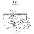
- FIGS 1 and 2 of the accompanying drawings are respectively a vertical cross-sectional view and a phantom perspective view of the essential portions of a circuit breaker disclosed in Japanese Laid-Open Utility Model Application No. 56-1063.
- the moving portions of the circuit breaker are contained within a housing 1 which comprises a base 1a and a cover 1b.
- a stator 2 having a fixed contact 2 mounted thereon is secured to the base 1a.
- a movable element 3 having a moving contact 3a mounted on one end thereof is supported by a contact arm 4 which is secured to a rotating crossbar 5.
- the movable element 3 is pivotably mounted on a pin 6 which passes through holes formed in two sides plates 4a of the contact arm 4 which are located on either side of the movable element 3.
- the other end of the movable element 3 is elastically supported by a spring 7 which is connected to the end of the contact arm 4.
- a C-shaped support member 8 is secured to the upper surface of the contact arm 4 by screws 9.
- the support member 8 supports an electrically-insulating rod 10 which extends perpendicularly upwards from the support member 8 and is secured thereto by a screw 9.
- a cylinder lock 11 for locking the circuit breaker is secured to the cover 1b of the housing 11.
- the lock 11 has a movable portion comprising a plate 11a which is secured to the cylinder of the lock 11 by a screw 9.
- the plate 11a can be rotated about the axis of the lock 11 so as to engage with the electrically-insulating rod 10 by turning a key 12 in the lock 11.
- the operating and trip mechanisms of the circuit breaker have been
- Figures 1 and 2 show the circuit breaker in an off state in which the contacts 2a and 3a are open.
- the plate 11a of the lock 11 is positioned in the path of movement of the electrically-insulating rod 10. Accordingly, the circuit breaker is prevented from operating and is locked in the off state. If the key 12 is rotated 90 degrees in the lock 11 in the direction shown by the arrow 13 in Figure 2, the plate 11a will pivot to the position shown by the dashed lines 11a ⁇ in the figures, out of the path of movement of the electrically-insulating rod 10. In this state, the crossbar 5 is free to pivot, the rod 10 can swing to the position shown by the dashed lines 10 ⁇ , and the circuit breaker can perform its normal switching operation.
- a movable element on which a moving contact is secured is directly pivoted on a crossbar, making a contact arm unnecessary.
- the crossbar has an engaging portion in the form of a protruding arm which is integrally formed thereon.
- a lock for locking the circuit breaker has a movable portion which can engage with the engaging portion of the crossbar.
- the crossbar is molded from a thermosetting resin, and the portion of the movable portion of the lock which engages with the engaging portion of the crossbar is an electrically-insulating rod.
- this circuit breaker is contained inside a housing 1 comprising a base 1a and a cover 1b.
- a stator 2 having a fixed contact 2a mounted thereon is secured to the base 1a.
- a movable element 20 having a moving contact 20a mounted on the end thereof is pivotably supported by a rotating crossbar 21.
- the crossbar 21 can be rotated between the open position shown in the drawings in which the contacts 2a and 20a are open, and a closed position in which the contacts are closed.
- the crossbar 21 is molded from a thermosetting resin and has three square holes 21a formed therein in each of which a movable element 20 can be mounted, although for simplicity, only a single movable element 20 is shown in the drawings.
- the illustrated crossbar 21 is able to support three movable elements 20, but there is no restriction on the number of holes 21a or movable elements 20.
- Each of the movable elements 20 is pivotably mounted on a pin 22 which fits into a pair of grooves 21b formed in the inner walls of one of the square holes 21a.
- a biasing torque is exerted on the movable elements 20 by biasing springs 23 which are mounted on the pins 22 and engage with notches 20b formed in the rear ends of the movable elements 20.
- the biasing springs 23 force the movable elements 20 to pivot about the pins 22 until they contact the bottom surfaces of the square holes 21a.
- the movable elements 20 are mounted on the crossbar 21 by being inserted into the square holes 21a from the back side, as shown in Figure 5.
- the crossbar 21 has a protruding arm 21c which is integrally formed on its upper portion. This arm 21c serves as an engaging member.
- a cylinder lock 11 is mounted on the cover 1b of the housing 1. It has a movable portion comprising a horizontal plate 11a which is secured to the cylinder of the lock 11 by a screw 9, a cylindrical portion 11b which is secured to the underside of the plate 11a at is outer end by another screw 9, and an electrically-insulating rod 11c which is secured to the underside of the cylindrical portion 11b by the same screw 9 which connects the plate 11a and the cylindrical portion 11b.
- the entire movable portion can be pivoted 90 degrees about the axis of the lock 11 between a locked position, shown by the solid lines in Figure 4, and an unlocked position, shown by the dashed lines 11a ⁇ in Figure 4, when a key 12 is turned in the lock 11.
- the electrically-insulating rod 11c engages with the engaging portion, i.e., the protruding arm 21c of the crossbar 21 and prevents the movement of the arm 21c.
- the engaging portion i.e., the protruding arm 21c of the crossbar 21
- a recess 11d having a flat surface which confronts the front surface of the protruding arm 21c is formed in the bottom end of the rod 11c. Since both the rod 11c and the protruding arm 21c are made of electrically-insulating materials, extremely high reliability is obtained.
- the position of the cylindrical portion 11b and the rod 11c along the plate 11a of the movable portion can be freely adjusted so as to minimize play between the rod 11c and the protruding arm 21c of the crossbar 21.
- the movable portion of the lock 11 is in a position such that the rod 11c engages with the protruding arm 21c of the crossbar 21, thus preventing the crossbar 21 from rotating.
- the lock 11 effectively locks the circuit breaker in the off state. If a key 12 is turned in the lock 11 in the direction of the arrow 13 in Figure 4, the movable portion will rotate by 90 degrees until the plate 11a reaches the position shown by the dashed lines 11a ⁇ . In this position, the rod 11c is out of the path of movement of the protruding arm 21c and no longer prevents the crossbar 21c from rotating, and the circuit breaker is free to perform normal switching movement.
- the lock 11 is positioned so as to lock the circuit breaker in an off state in which the contacts 2a and 20a are open. However, by merely altering the location of the lock 11, it can be made to lock the circuit breaker in the on state with the contacts 2a and 3a closed.
- a movable element 20 is directly pivoted on a crossbar 21 so that a contact arm 4 for supporting the movable element 20 is unnecessary. Furthermore, as a protruding arm 21c which engages with the movable portion of a lock is an integral portion of a molded crossbar 21, a separate support member 8 and connecting screws 9 therefor are unnecessary, resulting in a decrease in the number of parts. Also, as it is not necessary to form screw holes in a contact arm 4 or a support member 8, the ease of manufacture is increased and manufacturing costs can be decreased.
- circuit breaker uses the same operating mechanism, trip mechanism, and cylinder lock as a convention circuit breaker, it is simple to retrofit an existing circuit breaker to obtain one according to the present invention.
Landscapes
- Breakers (AREA)
Applications Claiming Priority (2)
| Application Number | Priority Date | Filing Date | Title |
|---|---|---|---|
| JP7828386U JPS62191047U (fr) | 1986-05-23 | 1986-05-23 | |
| JP78283/86 | 1986-05-23 |
Publications (3)
| Publication Number | Publication Date |
|---|---|
| EP0246727A2 true EP0246727A2 (fr) | 1987-11-25 |
| EP0246727A3 EP0246727A3 (en) | 1989-09-20 |
| EP0246727B1 EP0246727B1 (fr) | 1993-08-25 |
Family
ID=13657628
Family Applications (1)
| Application Number | Title | Priority Date | Filing Date |
|---|---|---|---|
| EP19870301284 Expired - Lifetime EP0246727B1 (fr) | 1986-05-23 | 1987-02-13 | Disjoncteur équipé d'une serrure |
Country Status (3)
| Country | Link |
|---|---|
| EP (1) | EP0246727B1 (fr) |
| JP (1) | JPS62191047U (fr) |
| DE (1) | DE3787116T2 (fr) |
Cited By (4)
| Publication number | Priority date | Publication date | Assignee | Title |
|---|---|---|---|---|
| EP1630836A1 (fr) * | 2004-08-25 | 2006-03-01 | EATON Corporation | Dispositif de verrouillage d'un arbre de déclenchement et appareil de commutation électrique l'utilisant |
| EP1944780A1 (fr) * | 2006-12-29 | 2008-07-16 | LS Industrial Systems Co., Ltd | Dispositif de verrou pour disjoncteur |
| EP2325856B1 (fr) * | 2009-11-19 | 2012-12-26 | LS Industrial Systems Co., Ltd | Dispositif de verrouillage pour disjoncteur |
| CN101494125B (zh) * | 2008-01-22 | 2013-02-06 | 赵建平 | 带有安全锁的断路器 |
Citations (3)
| Publication number | Priority date | Publication date | Assignee | Title |
|---|---|---|---|---|
| JPS561063Y2 (fr) * | 1976-08-04 | 1981-01-12 | ||
| EP0145990A2 (fr) * | 1983-12-19 | 1985-06-26 | Westinghouse Electric Corporation | Disjoncteur avec assemblage d'une traverse et d'un contact |
| US4554421A (en) * | 1984-01-09 | 1985-11-19 | Westinghouse Electric Corp. | Molded case circuit breaker with handle lock |
-
1986
- 1986-05-23 JP JP7828386U patent/JPS62191047U/ja active Pending
-
1987
- 1987-02-13 EP EP19870301284 patent/EP0246727B1/fr not_active Expired - Lifetime
- 1987-02-13 DE DE19873787116 patent/DE3787116T2/de not_active Expired - Fee Related
Patent Citations (3)
| Publication number | Priority date | Publication date | Assignee | Title |
|---|---|---|---|---|
| JPS561063Y2 (fr) * | 1976-08-04 | 1981-01-12 | ||
| EP0145990A2 (fr) * | 1983-12-19 | 1985-06-26 | Westinghouse Electric Corporation | Disjoncteur avec assemblage d'une traverse et d'un contact |
| US4554421A (en) * | 1984-01-09 | 1985-11-19 | Westinghouse Electric Corp. | Molded case circuit breaker with handle lock |
Cited By (4)
| Publication number | Priority date | Publication date | Assignee | Title |
|---|---|---|---|---|
| EP1630836A1 (fr) * | 2004-08-25 | 2006-03-01 | EATON Corporation | Dispositif de verrouillage d'un arbre de déclenchement et appareil de commutation électrique l'utilisant |
| EP1944780A1 (fr) * | 2006-12-29 | 2008-07-16 | LS Industrial Systems Co., Ltd | Dispositif de verrou pour disjoncteur |
| CN101494125B (zh) * | 2008-01-22 | 2013-02-06 | 赵建平 | 带有安全锁的断路器 |
| EP2325856B1 (fr) * | 2009-11-19 | 2012-12-26 | LS Industrial Systems Co., Ltd | Dispositif de verrouillage pour disjoncteur |
Also Published As
| Publication number | Publication date |
|---|---|
| EP0246727A3 (en) | 1989-09-20 |
| DE3787116D1 (de) | 1993-09-30 |
| DE3787116T2 (de) | 1994-04-21 |
| JPS62191047U (fr) | 1987-12-04 |
| EP0246727B1 (fr) | 1993-08-25 |
Similar Documents
| Publication | Publication Date | Title |
|---|---|---|
| JP3876003B2 (ja) | ロック可能な回転式ハンドル操作手段を有する回路遮断器 | |
| US4767895A (en) | Removable key off-lock switch having improved locking actuator | |
| US4662665A (en) | Auxiliary lock with an extensible device | |
| US5479800A (en) | Plastic lock | |
| EP0083508A1 (fr) | Structure de contact pour un mécanisme alternant d'un commutateur | |
| EP0246727B1 (fr) | Disjoncteur équipé d'une serrure | |
| CA2818181C (fr) | Appareil de commutation de courant electrique | |
| US3980845A (en) | Circuit breaker operator with defeates interlock mechanism | |
| US6609736B2 (en) | Horizontal motor-driven lock | |
| JPH01500941A (ja) | スィッチ、特に自動車用ステアリングコラムスィッチ | |
| JPH10172388A (ja) | 車両用レバースイッチの構造 | |
| JPH0922642A (ja) | 多方向切換スイッチ | |
| CA2874364C (fr) | Appareil de commutation de courant electrique | |
| CN214755492U (zh) | 直线移位过力矩保护部件 | |
| US6127909A (en) | Breaker mechanism for an electric circuit-breaker | |
| JPH017949Y2 (fr) | ||
| JPH0429461Y2 (fr) | ||
| JPS601478Y2 (ja) | 自動二輪車用の複合スイッチ | |
| JPH0316179Y2 (fr) | ||
| KR200160656Y1 (ko) | 리어시트백 장착용 록 어셈블리 | |
| JPH0632150Y2 (ja) | パチンコ機の施錠装置 | |
| JPH0419667Y2 (fr) | ||
| JPS5820816B2 (ja) | 自動車用コンビネ−シヨンスイツチ | |
| JPH0643954Y2 (ja) | マイクロスイッチ | |
| JP2595390B2 (ja) | 車両ロック機構のアクチュエータ用スイッチ |
Legal Events
| Date | Code | Title | Description |
|---|---|---|---|
| PUAI | Public reference made under article 153(3) epc to a published international application that has entered the european phase |
Free format text: ORIGINAL CODE: 0009012 |
|
| AK | Designated contracting states |
Kind code of ref document: A2 Designated state(s): DE FR GB |
|
| PUAL | Search report despatched |
Free format text: ORIGINAL CODE: 0009013 |
|
| AK | Designated contracting states |
Kind code of ref document: A3 Designated state(s): DE FR GB |
|
| 17P | Request for examination filed |
Effective date: 19891018 |
|
| 17Q | First examination report despatched |
Effective date: 19910918 |
|
| GRAA | (expected) grant |
Free format text: ORIGINAL CODE: 0009210 |
|
| AK | Designated contracting states |
Kind code of ref document: B1 Designated state(s): DE FR GB |
|
| REF | Corresponds to: |
Ref document number: 3787116 Country of ref document: DE Date of ref document: 19930930 |
|
| REG | Reference to a national code |
Ref country code: GB Ref legal event code: 727 |
|
| ET | Fr: translation filed | ||
| REG | Reference to a national code |
Ref country code: GB Ref legal event code: 727A |
|
| REG | Reference to a national code |
Ref country code: GB Ref legal event code: 727B |
|
| PLBE | No opposition filed within time limit |
Free format text: ORIGINAL CODE: 0009261 |
|
| STAA | Information on the status of an ep patent application or granted ep patent |
Free format text: STATUS: NO OPPOSITION FILED WITHIN TIME LIMIT |
|
| REG | Reference to a national code |
Ref country code: GB Ref legal event code: SP |
|
| 26N | No opposition filed | ||
| REG | Reference to a national code |
Ref country code: GB Ref legal event code: 746 Effective date: 19960611 |
|
| REG | Reference to a national code |
Ref country code: FR Ref legal event code: D6 |
|
| PGFP | Annual fee paid to national office [announced via postgrant information from national office to epo] |
Ref country code: FR Payment date: 19990209 Year of fee payment: 13 |
|
| PGFP | Annual fee paid to national office [announced via postgrant information from national office to epo] |
Ref country code: GB Payment date: 19990218 Year of fee payment: 13 |
|
| PGFP | Annual fee paid to national office [announced via postgrant information from national office to epo] |
Ref country code: DE Payment date: 19990223 Year of fee payment: 13 |
|
| PG25 | Lapsed in a contracting state [announced via postgrant information from national office to epo] |
Ref country code: GB Free format text: LAPSE BECAUSE OF NON-PAYMENT OF DUE FEES Effective date: 20000213 |
|
| GBPC | Gb: european patent ceased through non-payment of renewal fee |
Effective date: 20000213 |
|
| PG25 | Lapsed in a contracting state [announced via postgrant information from national office to epo] |
Ref country code: FR Free format text: LAPSE BECAUSE OF NON-PAYMENT OF DUE FEES Effective date: 20001031 |
|
| PG25 | Lapsed in a contracting state [announced via postgrant information from national office to epo] |
Ref country code: DE Free format text: LAPSE BECAUSE OF NON-PAYMENT OF DUE FEES Effective date: 20001201 |
|
| REG | Reference to a national code |
Ref country code: FR Ref legal event code: ST |