EP0246441A2 - Disposition de refroidissement pour moteurs à combustion interne - Google Patents
Disposition de refroidissement pour moteurs à combustion interne Download PDFInfo
- Publication number
- EP0246441A2 EP0246441A2 EP87105299A EP87105299A EP0246441A2 EP 0246441 A2 EP0246441 A2 EP 0246441A2 EP 87105299 A EP87105299 A EP 87105299A EP 87105299 A EP87105299 A EP 87105299A EP 0246441 A2 EP0246441 A2 EP 0246441A2
- Authority
- EP
- European Patent Office
- Prior art keywords
- engine
- cooling water
- turbocharger
- charge air
- air cooler
- Prior art date
- Legal status (The legal status is an assumption and is not a legal conclusion. Google has not performed a legal analysis and makes no representation as to the accuracy of the status listed.)
- Granted
Links
Images

Classifications
-
- F—MECHANICAL ENGINEERING; LIGHTING; HEATING; WEAPONS; BLASTING
- F02—COMBUSTION ENGINES; HOT-GAS OR COMBUSTION-PRODUCT ENGINE PLANTS
- F02B—INTERNAL-COMBUSTION PISTON ENGINES; COMBUSTION ENGINES IN GENERAL
- F02B29/00—Engines characterised by provision for charging or scavenging not provided for in groups F02B25/00, F02B27/00 or F02B33/00 - F02B39/00; Details thereof
- F02B29/04—Cooling of air intake supply
-
- F—MECHANICAL ENGINEERING; LIGHTING; HEATING; WEAPONS; BLASTING
- F01—MACHINES OR ENGINES IN GENERAL; ENGINE PLANTS IN GENERAL; STEAM ENGINES
- F01P—COOLING OF MACHINES OR ENGINES IN GENERAL; COOLING OF INTERNAL-COMBUSTION ENGINES
- F01P3/00—Liquid cooling
- F01P3/20—Cooling circuits not specific to a single part of engine or machine
-
- F—MECHANICAL ENGINEERING; LIGHTING; HEATING; WEAPONS; BLASTING
- F01—MACHINES OR ENGINES IN GENERAL; ENGINE PLANTS IN GENERAL; STEAM ENGINES
- F01P—COOLING OF MACHINES OR ENGINES IN GENERAL; COOLING OF INTERNAL-COMBUSTION ENGINES
- F01P7/00—Controlling of coolant flow
- F01P7/14—Controlling of coolant flow the coolant being liquid
- F01P7/16—Controlling of coolant flow the coolant being liquid by thermostatic control
-
- F—MECHANICAL ENGINEERING; LIGHTING; HEATING; WEAPONS; BLASTING
- F02—COMBUSTION ENGINES; HOT-GAS OR COMBUSTION-PRODUCT ENGINE PLANTS
- F02B—INTERNAL-COMBUSTION PISTON ENGINES; COMBUSTION ENGINES IN GENERAL
- F02B29/00—Engines characterised by provision for charging or scavenging not provided for in groups F02B25/00, F02B27/00 or F02B33/00 - F02B39/00; Details thereof
- F02B29/04—Cooling of air intake supply
- F02B29/0406—Layout of the intake air cooling or coolant circuit
- F02B29/0437—Liquid cooled heat exchangers
- F02B29/0443—Layout of the coolant or refrigerant circuit
-
- F—MECHANICAL ENGINEERING; LIGHTING; HEATING; WEAPONS; BLASTING
- F01—MACHINES OR ENGINES IN GENERAL; ENGINE PLANTS IN GENERAL; STEAM ENGINES
- F01P—COOLING OF MACHINES OR ENGINES IN GENERAL; COOLING OF INTERNAL-COMBUSTION ENGINES
- F01P2060/00—Cooling circuits using auxiliaries
- F01P2060/02—Intercooler
-
- F—MECHANICAL ENGINEERING; LIGHTING; HEATING; WEAPONS; BLASTING
- F01—MACHINES OR ENGINES IN GENERAL; ENGINE PLANTS IN GENERAL; STEAM ENGINES
- F01P—COOLING OF MACHINES OR ENGINES IN GENERAL; COOLING OF INTERNAL-COMBUSTION ENGINES
- F01P2060/00—Cooling circuits using auxiliaries
- F01P2060/12—Turbo charger
-
- Y—GENERAL TAGGING OF NEW TECHNOLOGICAL DEVELOPMENTS; GENERAL TAGGING OF CROSS-SECTIONAL TECHNOLOGIES SPANNING OVER SEVERAL SECTIONS OF THE IPC; TECHNICAL SUBJECTS COVERED BY FORMER USPC CROSS-REFERENCE ART COLLECTIONS [XRACs] AND DIGESTS
- Y02—TECHNOLOGIES OR APPLICATIONS FOR MITIGATION OR ADAPTATION AGAINST CLIMATE CHANGE
- Y02T—CLIMATE CHANGE MITIGATION TECHNOLOGIES RELATED TO TRANSPORTATION
- Y02T10/00—Road transport of goods or passengers
- Y02T10/10—Internal combustion engine [ICE] based vehicles
- Y02T10/12—Improving ICE efficiencies
Definitions
- the invention relates to a cooling arrangement for internal combustion engines of relatively large output with a water-cooled turbocharger, wherein a cooling water forced circulation, which is adjustable via a temperature sensor, comprises a cooler and a pump, and an intercooler is connected upstream at the cooling water inlet of the engine.
- a cooling water forced circulation which is adjustable via a temperature sensor, comprises a cooler and a pump, and an intercooler is connected upstream at the cooling water inlet of the engine.
- the object of the invention is to improve a generic arrangement that enables a reduction in the water flow rate and the pump drive power, as well as to enable favorable conditions with low engine load and a load-dependent self-regulation of the charge air temperature.
- turbocharger and engine are connected in series in the cooling circuit and in that the cooling water is passed first through the turbocharger and then through the engine.
- This arrangement requires a reduced cooling water flow and lower pump output.
- the motor is thus in a high-temperature circuit, which gives special advantages at low loads.
- the reduction in the amount of water through the series connection also enables load-dependent self-regulation of the charge air temperature, since the amount of heat to be dissipated in the engine and in the turbocharger causes a large temperature difference between the cooling water outlet on the engine and the inlet to the turbocharger, and also the integration of the charge air cooler in makes the cooling water circuit possible.
- cooling water circuit is formed by a series connection of the components in the form of charge air cooler, pump, turbocharger, engine, temperature sensor with control device and cooling water cooler.
- the charge air cooler is designed to be multi-flow.
- versatility is understood to mean that the tube bundle is divided into a plurality of sections which are connected in series with one another in order to increase the flow rate of the cooling water by arranging separating webs in the reversing hoods.
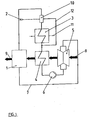
- Fig. 1 is a diagram of an arrangement
- Fig. 2 is a diagram of the temperature profile of the charge air and cooling water over the engine load.
- the cooling water circuit is formed via lines and guided by a pump 6 via an exhaust gas-driven turbocharger 5 and fed exclusively to an internal combustion engine 1 arranged in series.
- a temperature sensor 2 in the cooling water circuit which controls a control arrangement 10 which is in the circuit and is designed, for example, as a three-way valve for setting the cooling water temperature and for this purpose enables a cooling water cooler 3 through which a cooling medium flows to be switched on or bypassed via a bypass line 12.
- the circuit is then passed through a charge air cooler 4 and then connected to the turbocharger 5 via the pump 6.
- the fresh air inlet 8 is guided via the turbocharger 5 through the charge air cooler 4 to the engine 1 and leaves it as exhaust gas 9.
- the amount of heat to be dissipated in the engine 1 and turbocharger 5 causes a large temperature difference between the engine outlet and the turbocharger inlet due to the low cooling water volume flow, so that the charge air cooler 4 can also be integrated into the cooling water circuit.
- the flow temperature at the inlet to the charge air cooler 4 is almost the same as the temperature at the cooling water outlet of the engine 1, which temperature is usually regulated to a high level Warming the charge air to a temperature which is approximately only 5 to 10 K lower than the cooling water temperature and is important for the avoidance of corrosive precipitation.
- the flow temperature at the inlet to the charge air cooler 4 decreases to the extent that the total amount of heat to be removed increases.
- the charge air is cooled to a temperature that is about 10 to 15 K higher than the cooling water supply temperature when the engine is fully loaded.
- turbocharger 5 and engine 1 in the cooling water circuit therefore enables load-dependent self-regulation of the charge air temperature without additional regulating elements.
- a corresponding change in the cooling water volume flow and setpoint adjustment on the temperature sensor 2 thus enable simple adaptation to different, even extreme, environmental conditions, such as operation in the tropics or in the Arctic.
Landscapes
- Engineering & Computer Science (AREA)
- Chemical & Material Sciences (AREA)
- Combustion & Propulsion (AREA)
- Mechanical Engineering (AREA)
- General Engineering & Computer Science (AREA)
- Physics & Mathematics (AREA)
- Thermal Sciences (AREA)
- Supercharger (AREA)
Applications Claiming Priority (2)
| Application Number | Priority Date | Filing Date | Title |
|---|---|---|---|
| DE3617350A DE3617350C1 (de) | 1986-05-23 | 1986-05-23 | Kuehlanordnung fuer Verbrennungskraftmaschinen |
| DE3617350 | 1986-05-23 |
Publications (3)
| Publication Number | Publication Date |
|---|---|
| EP0246441A2 true EP0246441A2 (fr) | 1987-11-25 |
| EP0246441A3 EP0246441A3 (en) | 1988-12-28 |
| EP0246441B1 EP0246441B1 (fr) | 1990-07-04 |
Family
ID=6301453
Family Applications (1)
| Application Number | Title | Priority Date | Filing Date |
|---|---|---|---|
| EP87105299A Expired - Lifetime EP0246441B1 (fr) | 1986-05-23 | 1987-04-10 | Disposition de refroidissement pour moteurs à combustion interne |
Country Status (6)
| Country | Link |
|---|---|
| EP (1) | EP0246441B1 (fr) |
| JP (1) | JPS62279225A (fr) |
| KR (1) | KR910000081B1 (fr) |
| DE (2) | DE3617350C1 (fr) |
| FI (1) | FI92857C (fr) |
| NO (1) | NO161754C (fr) |
Cited By (1)
| Publication number | Priority date | Publication date | Assignee | Title |
|---|---|---|---|---|
| DE19845375A1 (de) * | 1998-10-02 | 2000-04-06 | Asea Brown Boveri | Verfahren und Vorrichtung zur indirekten Kühlung der Strömung in zwischen Rotoren und Statoren von Turbomaschinen ausgebildeten Radialspalten |
Families Citing this family (7)
| Publication number | Priority date | Publication date | Assignee | Title |
|---|---|---|---|---|
| DE3836463C2 (de) * | 1988-10-26 | 1998-09-10 | Ruhrgas Ag | Verfahren und Vorrichtung zur Nutzung der Abwärme eines Prozesses |
| DE4200661C2 (de) * | 1992-01-14 | 1994-07-28 | Horst Ochotzki | Verfahren zum Betrieb eines Schiffsdieselmotors |
| DE4222086A1 (de) * | 1992-07-04 | 1994-01-05 | Kloeckner Humboldt Deutz Ag | Brennkraftmaschine mit einem Verbrennungsluftkühler |
| DE19735306B4 (de) * | 1997-08-14 | 2010-11-11 | Audi Ag | Brennkraftmaschine |
| FR2772426B1 (fr) * | 1997-12-11 | 2000-02-04 | France Etat | Procede de refroidissement d'un moteur a combustion interne |
| DE10022967B4 (de) * | 2000-05-11 | 2007-03-08 | Daimlerchrysler Ag | Flüssigkeitsgekühlter Abgasturbolader |
| EP3517752B1 (fr) | 2018-01-29 | 2023-11-29 | Liebherr-Components Colmar SAS | Moteur à combustion interne comprenant un turbocompresseur |
Family Cites Families (8)
| Publication number | Priority date | Publication date | Assignee | Title |
|---|---|---|---|---|
| DE1476384B1 (de) * | 1965-05-11 | 1970-03-26 | Kloeckner Humboldt Deutz Ag | Fluessigkeitskreislauf fuer eine aufgeladene Brennkraftmaschine |
| DE2156704A1 (de) * | 1970-11-17 | 1972-05-18 | English Electric Diesels Ltd., Newton-le-Wollows, Lancashire (Großbritannien) | Wassergekühlte Brennkraftmaschine mit einem Lader |
| FR2305591A1 (fr) * | 1975-03-24 | 1976-10-22 | Semt | Procede et dispositif de regulation automatique de temperature d'air d'admission d'un moteur diesel fortement suralimente et a bas taux de compression volumetrique |
| DE2545227A1 (de) * | 1975-10-09 | 1977-04-28 | Motoren Werke Mannheim Ag | Vorrichtung zur erleichterung des anlassens eines dieselmotors |
| DE3047672A1 (de) * | 1980-12-18 | 1982-07-22 | Aktiengesellschaft Adolph Saurer, 9320 Arbon | Kuehleinrichtung zur kuehlung einer brennkraftmaschine und der ladeluft |
| NL8102340A (nl) * | 1981-05-12 | 1982-12-01 | Stork Werkspoor Diesel Bv | Werkwijze en inrichting voor het regelen van de temperatuur van het koelmedium bij een warmtebron met variabele warmteopbrengst. |
| FR2514484B1 (fr) * | 1981-10-12 | 1987-02-13 | Valeo | Boite a eau pour un echangeur de chaleur a circulation de liquide comprenant un passage de degazage du liquide et echangeur de chaleur comprenant cette boite a eau |
| DE3335434C2 (de) * | 1983-09-30 | 1985-12-12 | Krupp Mak Maschinenbau Gmbh, 2300 Kiel | Anordnung zur Beeinflussung der Kühlwassertemperatur von Verbrennungskraftmaschinen |
-
1986
- 1986-05-23 DE DE3617350A patent/DE3617350C1/de not_active Expired
-
1987
- 1987-04-10 EP EP87105299A patent/EP0246441B1/fr not_active Expired - Lifetime
- 1987-04-10 DE DE8787105299T patent/DE3763542D1/de not_active Expired - Fee Related
- 1987-04-24 KR KR1019870003967A patent/KR910000081B1/ko not_active Expired
- 1987-05-04 FI FI871947A patent/FI92857C/fi not_active IP Right Cessation
- 1987-05-07 NO NO871901A patent/NO161754C/no unknown
- 1987-05-14 JP JP62116022A patent/JPS62279225A/ja active Pending
Cited By (1)
| Publication number | Priority date | Publication date | Assignee | Title |
|---|---|---|---|---|
| DE19845375A1 (de) * | 1998-10-02 | 2000-04-06 | Asea Brown Boveri | Verfahren und Vorrichtung zur indirekten Kühlung der Strömung in zwischen Rotoren und Statoren von Turbomaschinen ausgebildeten Radialspalten |
Also Published As
| Publication number | Publication date |
|---|---|
| DE3617350C1 (de) | 1987-10-08 |
| NO161754C (no) | 1989-09-20 |
| EP0246441A3 (en) | 1988-12-28 |
| FI92857B (fi) | 1994-09-30 |
| NO871901L (no) | 1987-11-24 |
| EP0246441B1 (fr) | 1990-07-04 |
| FI871947A0 (fi) | 1987-05-04 |
| JPS62279225A (ja) | 1987-12-04 |
| FI871947A7 (fi) | 1987-11-24 |
| DE3763542D1 (de) | 1990-08-09 |
| NO161754B (no) | 1989-06-12 |
| KR880012867A (ko) | 1988-11-29 |
| NO871901D0 (no) | 1987-05-07 |
| KR910000081B1 (ko) | 1991-01-19 |
| FI92857C (fi) | 1995-01-10 |
Similar Documents
| Publication | Publication Date | Title |
|---|---|---|
| EP1101914B1 (fr) | Moteur à combustion interne refroidi par liquide | |
| DE4114704C1 (fr) | ||
| DE2706696A1 (de) | Kolbenbrennkraftmaschine mit abgasturboaufladung und verfahren zu ihrem betrieb | |
| DE102010010594B4 (de) | Kühlkreislauf für eine Brennkraftmaschine | |
| DE4231218C1 (en) | Exhaust-return system for pressure-charged engine - has exhaust turbocharger with compressor in by=pass pipe for gas returned to engine intake | |
| DE3028674A1 (de) | Vorrichtung zur temperaturregelung der ladeluft bei einem verbrennungsmotor | |
| EP0947679A2 (fr) | Moteur à combustion interne avec un turbocompresseur à géométrie variable et procédé pour le fonctionnement d'un tel moteur | |
| DE2640732A1 (de) | Ladeluft-waermetauscheranlage | |
| DE10317003A1 (de) | Kreislaufanordnung zur Kühlung von Ladeluft und Verfahren zum Betreiben einer derartigen Kreislaufanordnung | |
| DE2826373A1 (de) | Aufgeladener dieselmotor | |
| EP0246441A2 (fr) | Disposition de refroidissement pour moteurs à combustion interne | |
| EP0379542B1 (fr) | Dispositif de refroidissement d'un moteur a piston a combustion interne suralimente | |
| DE1128702B (de) | Fluessigkeits-Kuehlanlage fuer Brennkraftmaschinen mit Aufladung | |
| DE102009017719B4 (de) | Vorrichtung und Verfahren zur Regelung der Temperatur der Ladeluft | |
| DE2610378A1 (de) | Kuehleinrichtung fuer einen aufgeladenen wassergekuehlten verbrennungsmotor | |
| DE2545665B2 (de) | Antriebsanlage | |
| DE1526454A1 (de) | Verfahren zum Betrieb einer aufgeladenen Brennkraftmaschine mit Ladeluftkuehlung | |
| DE3406355C2 (fr) | ||
| DE2545227A1 (de) | Vorrichtung zur erleichterung des anlassens eines dieselmotors | |
| EP1728989A1 (fr) | Arrangement des turbocompresseurs à gaz d'échappement à plusieurs étages | |
| DE3043584A1 (de) | Einspritz-brennkraftmaschine | |
| DE102010009290B4 (de) | Kühlmittelkreislauf für eine Brennkraftmaschine mit Abgasrückführung | |
| DE19539604A1 (de) | Kühlsystem für Brennkraftmaschinen | |
| DE2542981C2 (de) | Verfahren zum Betrieb arbeitsraumbildender Brennkraftmaschinen mit Abgasturboaufladung | |
| DE102020213031A1 (de) | Brennkraftmaschine mit einer temperierbaren Druckregelvorrichtung für einen gasförmigen Kraftstoff |
Legal Events
| Date | Code | Title | Description |
|---|---|---|---|
| PUAI | Public reference made under article 153(3) epc to a published international application that has entered the european phase |
Free format text: ORIGINAL CODE: 0009012 |
|
| AK | Designated contracting states |
Kind code of ref document: A2 Designated state(s): DE FR GB SE |
|
| PUAL | Search report despatched |
Free format text: ORIGINAL CODE: 0009013 |
|
| RHK1 | Main classification (correction) |
Ipc: F01P 3/20 |
|
| AK | Designated contracting states |
Kind code of ref document: A3 Designated state(s): DE FR GB SE |
|
| 17P | Request for examination filed |
Effective date: 19890120 |
|
| 17Q | First examination report despatched |
Effective date: 19891116 |
|
| GRAA | (expected) grant |
Free format text: ORIGINAL CODE: 0009210 |
|
| AK | Designated contracting states |
Kind code of ref document: B1 Designated state(s): DE FR GB SE |
|
| REF | Corresponds to: |
Ref document number: 3763542 Country of ref document: DE Date of ref document: 19900809 |
|
| ET | Fr: translation filed | ||
| GBT | Gb: translation of ep patent filed (gb section 77(6)(a)/1977) | ||
| PLBE | No opposition filed within time limit |
Free format text: ORIGINAL CODE: 0009261 |
|
| STAA | Information on the status of an ep patent application or granted ep patent |
Free format text: STATUS: NO OPPOSITION FILED WITHIN TIME LIMIT |
|
| 26N | No opposition filed | ||
| PGFP | Annual fee paid to national office [announced via postgrant information from national office to epo] |
Ref country code: SE Payment date: 19950112 Year of fee payment: 9 |
|
| EAL | Se: european patent in force in sweden |
Ref document number: 87105299.9 |
|
| PGFP | Annual fee paid to national office [announced via postgrant information from national office to epo] |
Ref country code: GB Payment date: 19950330 Year of fee payment: 9 |
|
| PGFP | Annual fee paid to national office [announced via postgrant information from national office to epo] |
Ref country code: FR Payment date: 19950421 Year of fee payment: 9 |
|
| PG25 | Lapsed in a contracting state [announced via postgrant information from national office to epo] |
Ref country code: GB Effective date: 19960410 |
|
| PG25 | Lapsed in a contracting state [announced via postgrant information from national office to epo] |
Ref country code: SE Effective date: 19960411 |
|
| GBPC | Gb: european patent ceased through non-payment of renewal fee |
Effective date: 19960410 |
|
| PG25 | Lapsed in a contracting state [announced via postgrant information from national office to epo] |
Ref country code: FR Effective date: 19961227 |
|
| EUG | Se: european patent has lapsed |
Ref document number: 87105299.9 |
|
| REG | Reference to a national code |
Ref country code: FR Ref legal event code: ST |
|
| PGFP | Annual fee paid to national office [announced via postgrant information from national office to epo] |
Ref country code: DE Payment date: 19980204 Year of fee payment: 12 |
|
| PG25 | Lapsed in a contracting state [announced via postgrant information from national office to epo] |
Ref country code: DE Free format text: LAPSE BECAUSE OF NON-PAYMENT OF DUE FEES Effective date: 20000201 |