EP0246441A2 - Cooling arrangement for internal-combustion engines - Google Patents
Cooling arrangement for internal-combustion engines Download PDFInfo
- Publication number
- EP0246441A2 EP0246441A2 EP87105299A EP87105299A EP0246441A2 EP 0246441 A2 EP0246441 A2 EP 0246441A2 EP 87105299 A EP87105299 A EP 87105299A EP 87105299 A EP87105299 A EP 87105299A EP 0246441 A2 EP0246441 A2 EP 0246441A2
- Authority
- EP
- European Patent Office
- Prior art keywords
- cooling water
- turbocharger
- engine
- cooling
- air cooler
- Prior art date
- Legal status (The legal status is an assumption and is not a legal conclusion. Google has not performed a legal analysis and makes no representation as to the accuracy of the status listed.)
- Granted
Links
Images

Classifications
-
- F—MECHANICAL ENGINEERING; LIGHTING; HEATING; WEAPONS; BLASTING
- F02—COMBUSTION ENGINES; HOT-GAS OR COMBUSTION-PRODUCT ENGINE PLANTS
- F02B—INTERNAL-COMBUSTION PISTON ENGINES; COMBUSTION ENGINES IN GENERAL
- F02B29/00—Engines characterised by provision for charging or scavenging not provided for in groups F02B25/00, F02B27/00 or F02B33/00 - F02B39/00; Details thereof
- F02B29/04—Cooling of air intake supply
-
- F—MECHANICAL ENGINEERING; LIGHTING; HEATING; WEAPONS; BLASTING
- F01—MACHINES OR ENGINES IN GENERAL; ENGINE PLANTS IN GENERAL; STEAM ENGINES
- F01P—COOLING OF MACHINES OR ENGINES IN GENERAL; COOLING OF INTERNAL-COMBUSTION ENGINES
- F01P3/00—Liquid cooling
- F01P3/20—Cooling circuits not specific to a single part of engine or machine
-
- F—MECHANICAL ENGINEERING; LIGHTING; HEATING; WEAPONS; BLASTING
- F01—MACHINES OR ENGINES IN GENERAL; ENGINE PLANTS IN GENERAL; STEAM ENGINES
- F01P—COOLING OF MACHINES OR ENGINES IN GENERAL; COOLING OF INTERNAL-COMBUSTION ENGINES
- F01P7/00—Controlling of coolant flow
- F01P7/14—Controlling of coolant flow the coolant being liquid
- F01P7/16—Controlling of coolant flow the coolant being liquid by thermostatic control
-
- F—MECHANICAL ENGINEERING; LIGHTING; HEATING; WEAPONS; BLASTING
- F02—COMBUSTION ENGINES; HOT-GAS OR COMBUSTION-PRODUCT ENGINE PLANTS
- F02B—INTERNAL-COMBUSTION PISTON ENGINES; COMBUSTION ENGINES IN GENERAL
- F02B29/00—Engines characterised by provision for charging or scavenging not provided for in groups F02B25/00, F02B27/00 or F02B33/00 - F02B39/00; Details thereof
- F02B29/04—Cooling of air intake supply
- F02B29/0406—Layout of the intake air cooling or coolant circuit
- F02B29/0437—Liquid cooled heat exchangers
- F02B29/0443—Layout of the coolant or refrigerant circuit
-
- F—MECHANICAL ENGINEERING; LIGHTING; HEATING; WEAPONS; BLASTING
- F01—MACHINES OR ENGINES IN GENERAL; ENGINE PLANTS IN GENERAL; STEAM ENGINES
- F01P—COOLING OF MACHINES OR ENGINES IN GENERAL; COOLING OF INTERNAL-COMBUSTION ENGINES
- F01P2060/00—Cooling circuits using auxiliaries
- F01P2060/02—Intercooler
-
- F—MECHANICAL ENGINEERING; LIGHTING; HEATING; WEAPONS; BLASTING
- F01—MACHINES OR ENGINES IN GENERAL; ENGINE PLANTS IN GENERAL; STEAM ENGINES
- F01P—COOLING OF MACHINES OR ENGINES IN GENERAL; COOLING OF INTERNAL-COMBUSTION ENGINES
- F01P2060/00—Cooling circuits using auxiliaries
- F01P2060/12—Turbo charger
-
- Y—GENERAL TAGGING OF NEW TECHNOLOGICAL DEVELOPMENTS; GENERAL TAGGING OF CROSS-SECTIONAL TECHNOLOGIES SPANNING OVER SEVERAL SECTIONS OF THE IPC; TECHNICAL SUBJECTS COVERED BY FORMER USPC CROSS-REFERENCE ART COLLECTIONS [XRACs] AND DIGESTS
- Y02—TECHNOLOGIES OR APPLICATIONS FOR MITIGATION OR ADAPTATION AGAINST CLIMATE CHANGE
- Y02T—CLIMATE CHANGE MITIGATION TECHNOLOGIES RELATED TO TRANSPORTATION
- Y02T10/00—Road transport of goods or passengers
- Y02T10/10—Internal combustion engine [ICE] based vehicles
- Y02T10/12—Improving ICE efficiencies
Definitions
- the invention relates to a cooling arrangement for internal combustion engines of relatively large output with a water-cooled turbocharger, wherein a cooling water forced circulation, which is adjustable via a temperature sensor, comprises a cooler and a pump, and an intercooler is connected upstream at the cooling water inlet of the engine.
- a cooling water forced circulation which is adjustable via a temperature sensor, comprises a cooler and a pump, and an intercooler is connected upstream at the cooling water inlet of the engine.
- the object of the invention is to improve a generic arrangement that enables a reduction in the water flow rate and the pump drive power, as well as to enable favorable conditions with low engine load and a load-dependent self-regulation of the charge air temperature.
- turbocharger and engine are connected in series in the cooling circuit and in that the cooling water is passed first through the turbocharger and then through the engine.
- This arrangement requires a reduced cooling water flow and lower pump output.
- the motor is thus in a high-temperature circuit, which gives special advantages at low loads.
- the reduction in the amount of water through the series connection also enables load-dependent self-regulation of the charge air temperature, since the amount of heat to be dissipated in the engine and in the turbocharger causes a large temperature difference between the cooling water outlet on the engine and the inlet to the turbocharger, and also the integration of the charge air cooler in makes the cooling water circuit possible.
- cooling water circuit is formed by a series connection of the components in the form of charge air cooler, pump, turbocharger, engine, temperature sensor with control device and cooling water cooler.
- the charge air cooler is designed to be multi-flow.
- versatility is understood to mean that the tube bundle is divided into a plurality of sections which are connected in series with one another in order to increase the flow rate of the cooling water by arranging separating webs in the reversing hoods.
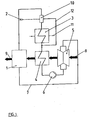
- Fig. 1 is a diagram of an arrangement
- Fig. 2 is a diagram of the temperature profile of the charge air and cooling water over the engine load.
- the cooling water circuit is formed via lines and guided by a pump 6 via an exhaust gas-driven turbocharger 5 and fed exclusively to an internal combustion engine 1 arranged in series.
- a temperature sensor 2 in the cooling water circuit which controls a control arrangement 10 which is in the circuit and is designed, for example, as a three-way valve for setting the cooling water temperature and for this purpose enables a cooling water cooler 3 through which a cooling medium flows to be switched on or bypassed via a bypass line 12.
- the circuit is then passed through a charge air cooler 4 and then connected to the turbocharger 5 via the pump 6.
- the fresh air inlet 8 is guided via the turbocharger 5 through the charge air cooler 4 to the engine 1 and leaves it as exhaust gas 9.
- the amount of heat to be dissipated in the engine 1 and turbocharger 5 causes a large temperature difference between the engine outlet and the turbocharger inlet due to the low cooling water volume flow, so that the charge air cooler 4 can also be integrated into the cooling water circuit.
- the flow temperature at the inlet to the charge air cooler 4 is almost the same as the temperature at the cooling water outlet of the engine 1, which temperature is usually regulated to a high level Warming the charge air to a temperature which is approximately only 5 to 10 K lower than the cooling water temperature and is important for the avoidance of corrosive precipitation.
- the flow temperature at the inlet to the charge air cooler 4 decreases to the extent that the total amount of heat to be removed increases.
- the charge air is cooled to a temperature that is about 10 to 15 K higher than the cooling water supply temperature when the engine is fully loaded.
- turbocharger 5 and engine 1 in the cooling water circuit therefore enables load-dependent self-regulation of the charge air temperature without additional regulating elements.
- a corresponding change in the cooling water volume flow and setpoint adjustment on the temperature sensor 2 thus enable simple adaptation to different, even extreme, environmental conditions, such as operation in the tropics or in the Arctic.
Abstract
Description
Die Erfindung bezieht sich auf eine Kühlanordnung für Verbrennungskraftmaschinen relativ großer Leistung mit einem wassergekühlten Turbolader, wobei ein über einen Temperaturfühler regelbarer, einen Kühler und eine Pumpe umfassender Kühlwasserzwangsumlauf ausgebildet und am Kühlwassereintritt des Motors ein Ladeluftkühler vorgeschaltet ist.The invention relates to a cooling arrangement for internal combustion engines of relatively large output with a water-cooled turbocharger, wherein a cooling water forced circulation, which is adjustable via a temperature sensor, comprises a cooler and a pump, and an intercooler is connected upstream at the cooling water inlet of the engine.
Bei Anordnungen dieser Art ist eine Parallelschaltung von Turbolader und Motor gemäß der DE-OS 30 47 672 vorgesehen. Hierbei besteht der Mangel, daß die erforderliche Kühlwasserdurchsatzmenge relativ hoch ist, um eine zulässige Aufwärmung des Kühlwassers im Turbolader nicht zu überschreiten. Damit ist auch der Aufwand für die Antriebsenergie der Pumpe relativ hoch und es wird das Verhältnis von Verlustenergie zu Nutzenergie ungünstig beeinflußt.In arrangements of this type, a parallel connection of the turbocharger and engine according to DE-OS 30 47 672 is provided. There is a lack here that the required cooling water throughput is relatively high so as not to exceed an admissible heating of the cooling water in the turbocharger. The expenditure for the drive energy of the pump is thus also relatively high and the ratio of lost energy to useful energy is adversely affected.
Aufgabe der Erfindung ist es, eine gattungsgemäße Anordnung zu verbessern, die eine Reduzierung der Wasserdurchsatzmenge und der Pumpenantriebsleistung ermöglicht, sowie günstige Verhältnisse bei geringer Motorbelastung und eine lastabhängige Selbstregelung der Ladelufttemperatur zu ermöglichen.The object of the invention is to improve a generic arrangement that enables a reduction in the water flow rate and the pump drive power, as well as to enable favorable conditions with low engine load and a load-dependent self-regulation of the charge air temperature.
Die Lösung dieser Aufgabe erfolgt erfindungsgemäß dadurch, daß Turbolader und Motor im Kühlkreislauf hintereinander geschaltet sind und daß das Kühlwasser zuerst durch den Turbolader und danach durch den Motor geführt ist.This object is achieved according to the invention in that the turbocharger and engine are connected in series in the cooling circuit and in that the cooling water is passed first through the turbocharger and then through the engine.
Durch diese Anordnung wird ein reduzierter Kühlwasservolumenstrom und geringere Pumpenleistung erforderlich. Der Motor befindet sich damit in einem Hochtemperaturkreis, wobei dieses bei geringen Belastungen besondere Vorteile ergibt. Die Verminderung der Wassermenge durch die Reihenschaltung ermöglicht außerdem eine lastabhängige Selbstregelung der Ladelufttemperatur, da die abzuführende Wärmemenge im Motor und im Turbolader aufgrund des geringen Kühlwasservolumenstroms eine große Temperaturdifferenz zwischen dem Kühlwasseraustritt am Motor und dem Eintritt in den Turbolader bewirkt und auch die Einbindung des Ladeluftkühlers in den Kühlwasserkreislauf möglich macht.This arrangement requires a reduced cooling water flow and lower pump output. The motor is thus in a high-temperature circuit, which gives special advantages at low loads. The reduction in the amount of water through the series connection also enables load-dependent self-regulation of the charge air temperature, since the amount of heat to be dissipated in the engine and in the turbocharger causes a large temperature difference between the cooling water outlet on the engine and the inlet to the turbocharger, and also the integration of the charge air cooler in makes the cooling water circuit possible.
Eine vorteilhafte Anordnung einer Einkreiskühlung wird dadurch gebildet, daß der Kühlwasserkreislauf durch eine Reihenschaltung der Komponenten in Form von Ladeluftkühler, Pumpe, Turbolader, Motor, Temperaturfühler mit Regeleinrichtung und Kühlwasserkühler gebildet ist.An advantageous arrangement of a single-circuit cooling is formed in that the cooling water circuit is formed by a series connection of the components in the form of charge air cooler, pump, turbocharger, engine, temperature sensor with control device and cooling water cooler.
Um den Durchsatz von kleinen Wasser- und großen Luftmengen zu erzielen, ist vorgesehen, daß der Ladeluftkühler vielflutig ausgebildet ist.In order to achieve the throughput of small amounts of water and large amounts of air, it is provided that the charge air cooler is designed to be multi-flow.
Unter Vielflutigkeit wird dabei verstanden, daß kühlwasserseitig durch eine Anordnung von Trennstegen in den Umkehrhauben das Rohrbündel in mehrere Sektionen aufgeteilt wird, die untereinander in Reihe geschaltet sind, um die Strömungsgeschwindigkeit des Kühlwassers zu erhöhen.In this context, versatility is understood to mean that the tube bundle is divided into a plurality of sections which are connected in series with one another in order to increase the flow rate of the cooling water by arranging separating webs in the reversing hoods.
In der Zeichnung ist ein Ausführungsbeispiel der Erfindung schematisch dargestellt. Es zeigen:In the drawing, an embodiment of the invention is shown schematically. Show it:
Bei der dargestellten Anordnung wird der Kühlwasserkreislauf über Leitungen gebildet und durch eine Pumpe 6 über einen abgasgetriebenen Turbolader 5 geführt sowie ausschließlich einer in Reihenschaltung angeordneter Verbrennungskraftmaschine 1 zugeführt. Am Motoraustritt befindet sich im Kühlwasserkreislauf ein Temperaturfühler 2, der eine im Kreislauf liegende Regelanordnung 10 steuert, die beispielsweise als Drei-Wege-Ventil zur Einstellung der Kühlwassertemperatur ausgebildet ist und ermöglicht zu diesem Zweck einen Kühlwasserkühler 3, der von einem Kühlmedium durchströmt wird, einzuschalten bzw. über eine Bypassleitung 12 umgangen wird. Anschließend wird der Kreislauf über einen Ladeluftkühler 4 geführt und dann über die Pumpe 6 an den Turbolader 5 angeschlossen. Der Frischlufteintritt 8 ist über den Turbolader 5 durch den Ladeluftkühler 4 zum Motor 1 geführt und verläßt diesen als Abgas 9.In the arrangement shown, the cooling water circuit is formed via lines and guided by a pump 6 via an exhaust gas-driven turbocharger 5 and fed exclusively to an internal combustion engine 1 arranged in series. At the engine outlet there is a
Die abzuführende Wärmemenge im Motor 1 und Turbolader 5 bewirkt aufgrund des geringen Kühlwasservolumenstroms eine große Temperaturdifferenz zwischen Motoraustritt und Turbolader-Eintritt, so daß auch der Ladeluftkühler 4 in den Kühlwasserkreislauf eingebunden werden kann.The amount of heat to be dissipated in the engine 1 and turbocharger 5 causes a large temperature difference between the engine outlet and the turbocharger inlet due to the low cooling water volume flow, so that the
Im Leerlauf des Motors 1 ist bei geringster abzuführender Wärmemenge die Vorlauftemperatur am Eintritt in den Ladeluftkühler 4 nahezu gleich der meistens auf ein hohes Niveau eingeregelten Temperatur am Kühlwasseraustritt der Kraftmaschine 1. Hierdurch wird eine Anwärmung der Ladeluft auf eine Temperatur bewirkt, die ungefähr nur 5 bis 10 K niedriger als die Kühlwassertemperatur ist und für die Vermeidung von korrodierenden Niederschlägen wichtig ist.When the engine 1 is idling and the smallest amount of heat to be dissipated, the flow temperature at the inlet to the
Mit steigender Belastung des Motors 1 und zunehmender Einschaltung des Kühlwasserkühlers 3 zur Konstanthaltung der Temperatur beim Temperaturfühler 2 sinkt die Vorlauftemperatur am Eintritt in den Ladeluftkühler 4 in dem Maße, wie die abzuführende Gesamtwärmemenge zunimmt. Es erfolgt hierbei eine Abkühlung der Ladeluft auf eine Temperatur, die bei voller Belastung des Motors etwa 10 bis 15 K höher als die Kühlwasser-Vorlauftemperatur ist.With increasing load on the engine 1 and increasing activation of the
Durch die Reihenschaltung von Turbolader 5 und Motor 1 im Kühlwasserkreislauf wird daher eine lastabhängige Selbstregelung der Ladelufttemperatur ohne zusätzliche Regelorgane ermöglicht.The series connection of turbocharger 5 and engine 1 in the cooling water circuit therefore enables load-dependent self-regulation of the charge air temperature without additional regulating elements.
Eine entsprechende Veränderung des Kühlwasservolumenstroms und Sollwertverstellung am Temperaturfühler 2 ermöglichen damit eine einfache Anpassung an unterschiedliche, auch extreme Umgebungsbedingungen, wie einen Betrieb in den Tropen oder in der Arktis.A corresponding change in the cooling water volume flow and setpoint adjustment on the
Claims (3)
Applications Claiming Priority (2)
| Application Number | Priority Date | Filing Date | Title |
|---|---|---|---|
| DE3617350 | 1986-05-23 | ||
| DE3617350A DE3617350C1 (en) | 1986-05-23 | 1986-05-23 | Cooling arrangement for internal combustion engines |
Publications (3)
| Publication Number | Publication Date |
|---|---|
| EP0246441A2 true EP0246441A2 (en) | 1987-11-25 |
| EP0246441A3 EP0246441A3 (en) | 1988-12-28 |
| EP0246441B1 EP0246441B1 (en) | 1990-07-04 |
Family
ID=6301453
Family Applications (1)
| Application Number | Title | Priority Date | Filing Date |
|---|---|---|---|
| EP87105299A Expired - Lifetime EP0246441B1 (en) | 1986-05-23 | 1987-04-10 | Cooling arrangement for internal-combustion engines |
Country Status (6)
| Country | Link |
|---|---|
| EP (1) | EP0246441B1 (en) |
| JP (1) | JPS62279225A (en) |
| KR (1) | KR910000081B1 (en) |
| DE (2) | DE3617350C1 (en) |
| FI (1) | FI92857C (en) |
| NO (1) | NO161754C (en) |
Cited By (1)
| Publication number | Priority date | Publication date | Assignee | Title |
|---|---|---|---|---|
| DE19845375A1 (en) * | 1998-10-02 | 2000-04-06 | Asea Brown Boveri | Indirect cooling process for flow in gap between turbine rotor and stator, involving use of water to cool stator part adjacent to gap |
Families Citing this family (7)
| Publication number | Priority date | Publication date | Assignee | Title |
|---|---|---|---|---|
| DE3836463C2 (en) * | 1988-10-26 | 1998-09-10 | Ruhrgas Ag | Method and device for using waste heat from a process |
| DE4200661C2 (en) * | 1992-01-14 | 1994-07-28 | Horst Ochotzki | Method for operating a marine diesel engine |
| DE4222086A1 (en) * | 1992-07-04 | 1994-01-05 | Kloeckner Humboldt Deutz Ag | IC engine with combustion air cooler - has reduced nitrous oxide emission at full load or high power at lower combustion air temp. |
| DE19735306B4 (en) * | 1997-08-14 | 2010-11-11 | Audi Ag | Internal combustion engine |
| FR2772426B1 (en) * | 1997-12-11 | 2000-02-04 | France Etat | COOLING METHOD OF AN INTERNAL COMBUSTION ENGINE |
| DE10022967B4 (en) * | 2000-05-11 | 2007-03-08 | Daimlerchrysler Ag | Liquid cooled turbocharger |
| US10920651B2 (en) | 2018-01-29 | 2021-02-16 | Liebherr-Components Colmar Sas | Internal combustion engine comprising a turbocharger |
Citations (7)
| Publication number | Priority date | Publication date | Assignee | Title |
|---|---|---|---|---|
| DE2156704A1 (en) * | 1970-11-17 | 1972-05-18 | English Electric Diesels Ltd., Newton-le-Wollows, Lancashire (Großbritannien) | Water-cooled internal combustion engine with a charger |
| FR2305591A1 (en) * | 1975-03-24 | 1976-10-22 | Semt | Diesel engine inlet air temp. control - uses fuel injector position to control valve recycling fluid from cooler |
| DE2545227A1 (en) * | 1975-10-09 | 1977-04-28 | Motoren Werke Mannheim Ag | Supercharged compression ignition engine - maintains combustion air at constant temperature by heater and cooler systems |
| DE3047672A1 (en) * | 1980-12-18 | 1982-07-22 | Aktiengesellschaft Adolph Saurer, 9320 Arbon | COOLING DEVICE FOR COOLING AN INTERNAL COMBUSTION ENGINE AND THE CHARGING AIR |
| WO1982004095A1 (en) * | 1981-05-12 | 1982-11-25 | Werkspoor Diesel Bv Stork | Method and device for coolant temperature control |
| FR2514484A1 (en) * | 1981-10-12 | 1983-04-15 | Valeo | Header tank for vehicle radiator - has collector and separator chambers with partition and gas passage |
| DE3335434A1 (en) * | 1983-09-30 | 1985-04-18 | Krupp Mak Maschinenbau Gmbh, 2300 Kiel | Arrangement for influencing the cooling water temperature of internal combustion engines |
Family Cites Families (1)
| Publication number | Priority date | Publication date | Assignee | Title |
|---|---|---|---|---|
| DE1476384B1 (en) * | 1965-05-11 | 1970-03-26 | Kloeckner Humboldt Deutz Ag | Fluid circuit for a supercharged internal combustion engine |
-
1986
- 1986-05-23 DE DE3617350A patent/DE3617350C1/en not_active Expired
-
1987
- 1987-04-10 DE DE8787105299T patent/DE3763542D1/en not_active Expired - Fee Related
- 1987-04-10 EP EP87105299A patent/EP0246441B1/en not_active Expired - Lifetime
- 1987-04-24 KR KR1019870003967A patent/KR910000081B1/en not_active IP Right Cessation
- 1987-05-04 FI FI871947A patent/FI92857C/en not_active IP Right Cessation
- 1987-05-07 NO NO871901A patent/NO161754C/en unknown
- 1987-05-14 JP JP62116022A patent/JPS62279225A/en active Pending
Patent Citations (7)
| Publication number | Priority date | Publication date | Assignee | Title |
|---|---|---|---|---|
| DE2156704A1 (en) * | 1970-11-17 | 1972-05-18 | English Electric Diesels Ltd., Newton-le-Wollows, Lancashire (Großbritannien) | Water-cooled internal combustion engine with a charger |
| FR2305591A1 (en) * | 1975-03-24 | 1976-10-22 | Semt | Diesel engine inlet air temp. control - uses fuel injector position to control valve recycling fluid from cooler |
| DE2545227A1 (en) * | 1975-10-09 | 1977-04-28 | Motoren Werke Mannheim Ag | Supercharged compression ignition engine - maintains combustion air at constant temperature by heater and cooler systems |
| DE3047672A1 (en) * | 1980-12-18 | 1982-07-22 | Aktiengesellschaft Adolph Saurer, 9320 Arbon | COOLING DEVICE FOR COOLING AN INTERNAL COMBUSTION ENGINE AND THE CHARGING AIR |
| WO1982004095A1 (en) * | 1981-05-12 | 1982-11-25 | Werkspoor Diesel Bv Stork | Method and device for coolant temperature control |
| FR2514484A1 (en) * | 1981-10-12 | 1983-04-15 | Valeo | Header tank for vehicle radiator - has collector and separator chambers with partition and gas passage |
| DE3335434A1 (en) * | 1983-09-30 | 1985-04-18 | Krupp Mak Maschinenbau Gmbh, 2300 Kiel | Arrangement for influencing the cooling water temperature of internal combustion engines |
Non-Patent Citations (1)
| Title |
|---|
| GLASERS ANNALEN, Band 87, Nr. 5, Mai 1963, Seiten 296-312, Berlin, DE; E. PFLUG: "Dieselmotoren, Kühlanlagen und elektrische Ausrüstung der neuen Diesellokomotiven V200" * |
Cited By (1)
| Publication number | Priority date | Publication date | Assignee | Title |
|---|---|---|---|---|
| DE19845375A1 (en) * | 1998-10-02 | 2000-04-06 | Asea Brown Boveri | Indirect cooling process for flow in gap between turbine rotor and stator, involving use of water to cool stator part adjacent to gap |
Also Published As
| Publication number | Publication date |
|---|---|
| NO871901D0 (en) | 1987-05-07 |
| JPS62279225A (en) | 1987-12-04 |
| FI871947A0 (en) | 1987-05-04 |
| KR880012867A (en) | 1988-11-29 |
| NO871901L (en) | 1987-11-24 |
| FI871947A (en) | 1987-11-24 |
| NO161754C (en) | 1989-09-20 |
| FI92857B (en) | 1994-09-30 |
| EP0246441A3 (en) | 1988-12-28 |
| NO161754B (en) | 1989-06-12 |
| FI92857C (en) | 1995-01-10 |
| DE3763542D1 (en) | 1990-08-09 |
| EP0246441B1 (en) | 1990-07-04 |
| DE3617350C1 (en) | 1987-10-08 |
| KR910000081B1 (en) | 1991-01-19 |
Similar Documents
| Publication | Publication Date | Title |
|---|---|---|
| EP1101914B1 (en) | Liquid cooled internal combustion engine | |
| DE102010010594B4 (en) | Cooling circuit for an internal combustion engine | |
| CH624183A5 (en) | ||
| EP0947679A2 (en) | Internal combustion engine with a VTG turbo-charger and method of operating a VTG turbocharged engine | |
| DE60306954T2 (en) | IMPROVED DEVICE FOR THE THERMAL CONTROL OF THE INTAKE AIR OF A COMBUSTION ENGINE AND RECYCLED INTERNAL COMBUSTION ENGINE EXHAUST GAS | |
| DE102012200562A1 (en) | engine system | |
| DE2706696A1 (en) | PISTON ENGINE WITH EXHAUST GAS TURBOCHARGING AND PROCEDURES FOR ITS OPERATION | |
| DE10317003A1 (en) | Circuit arrangement for cooling charge air and method for operating such a circuit arrangement | |
| DE19961825A1 (en) | Cooling-heating circuit with two coolers | |
| DE3028674A1 (en) | DEVICE FOR TEMPERATURE CONTROL OF THE CHARGE AIR IN AN INTERNAL COMBUSTION ENGINE | |
| WO2007012493A1 (en) | Cooling system for a vehicle, and method for the operation of a cooling system | |
| DE10146346A1 (en) | Coolant circuit | |
| EP1623101B1 (en) | Circuit for cooling charge air, and method for operating such a circuit | |
| EP0246441B1 (en) | Cooling arrangement for internal-combustion engines | |
| DE2826373A1 (en) | CHARGED DIESEL ENGINE | |
| DE1128702B (en) | Liquid cooling system for internal combustion engines with charging | |
| EP0379542B1 (en) | Device for cooling a supercharged piston-type internal combustion engine | |
| DE2610378A1 (en) | Cooling system for supercharged IC engine - using single cycle water cooling while supercharged air is heated at low loads | |
| DE2438118A1 (en) | METHOD AND DEVICE FOR HEATING THE INTAKE AIR OF A CHARGED DIESEL ENGINE AT LOW LOADS | |
| DE102009017719B4 (en) | Apparatus and method for controlling the temperature of the charge air | |
| DE19537800A1 (en) | Exhaust gas system with heat exchanger | |
| DE3406355C2 (en) | ||
| EP3739180B1 (en) | Cooling circuit arrangement of a combustion engine | |
| DE2545227A1 (en) | Supercharged compression ignition engine - maintains combustion air at constant temperature by heater and cooler systems | |
| DE3708351A1 (en) | Forced circulation cooling system |
Legal Events
| Date | Code | Title | Description |
|---|---|---|---|
| PUAI | Public reference made under article 153(3) epc to a published international application that has entered the european phase |
Free format text: ORIGINAL CODE: 0009012 |
|
| AK | Designated contracting states |
Kind code of ref document: A2 Designated state(s): DE FR GB SE |
|
| PUAL | Search report despatched |
Free format text: ORIGINAL CODE: 0009013 |
|
| RHK1 | Main classification (correction) |
Ipc: F01P 3/20 |
|
| AK | Designated contracting states |
Kind code of ref document: A3 Designated state(s): DE FR GB SE |
|
| 17P | Request for examination filed |
Effective date: 19890120 |
|
| 17Q | First examination report despatched |
Effective date: 19891116 |
|
| GRAA | (expected) grant |
Free format text: ORIGINAL CODE: 0009210 |
|
| AK | Designated contracting states |
Kind code of ref document: B1 Designated state(s): DE FR GB SE |
|
| REF | Corresponds to: |
Ref document number: 3763542 Country of ref document: DE Date of ref document: 19900809 |
|
| ET | Fr: translation filed | ||
| GBT | Gb: translation of ep patent filed (gb section 77(6)(a)/1977) | ||
| PLBE | No opposition filed within time limit |
Free format text: ORIGINAL CODE: 0009261 |
|
| STAA | Information on the status of an ep patent application or granted ep patent |
Free format text: STATUS: NO OPPOSITION FILED WITHIN TIME LIMIT |
|
| 26N | No opposition filed | ||
| PGFP | Annual fee paid to national office [announced via postgrant information from national office to epo] |
Ref country code: SE Payment date: 19950112 Year of fee payment: 9 |
|
| EAL | Se: european patent in force in sweden |
Ref document number: 87105299.9 |
|
| PGFP | Annual fee paid to national office [announced via postgrant information from national office to epo] |
Ref country code: GB Payment date: 19950330 Year of fee payment: 9 |
|
| PGFP | Annual fee paid to national office [announced via postgrant information from national office to epo] |
Ref country code: FR Payment date: 19950421 Year of fee payment: 9 |
|
| PG25 | Lapsed in a contracting state [announced via postgrant information from national office to epo] |
Ref country code: GB Effective date: 19960410 |
|
| PG25 | Lapsed in a contracting state [announced via postgrant information from national office to epo] |
Ref country code: SE Effective date: 19960411 |
|
| GBPC | Gb: european patent ceased through non-payment of renewal fee |
Effective date: 19960410 |
|
| PG25 | Lapsed in a contracting state [announced via postgrant information from national office to epo] |
Ref country code: FR Effective date: 19961227 |
|
| EUG | Se: european patent has lapsed |
Ref document number: 87105299.9 |
|
| REG | Reference to a national code |
Ref country code: FR Ref legal event code: ST |
|
| PGFP | Annual fee paid to national office [announced via postgrant information from national office to epo] |
Ref country code: DE Payment date: 19980204 Year of fee payment: 12 |
|
| PG25 | Lapsed in a contracting state [announced via postgrant information from national office to epo] |
Ref country code: DE Free format text: LAPSE BECAUSE OF NON-PAYMENT OF DUE FEES Effective date: 20000201 |