EP0246212A2 - Protection against vibrations at a motor driven vibration generating handtool - Google Patents
Protection against vibrations at a motor driven vibration generating handtool Download PDFInfo
- Publication number
- EP0246212A2 EP0246212A2 EP87850151A EP87850151A EP0246212A2 EP 0246212 A2 EP0246212 A2 EP 0246212A2 EP 87850151 A EP87850151 A EP 87850151A EP 87850151 A EP87850151 A EP 87850151A EP 0246212 A2 EP0246212 A2 EP 0246212A2
- Authority
- EP
- European Patent Office
- Prior art keywords
- housing
- arrangement
- handle
- resilient element
- vibration
- Prior art date
- Legal status (The legal status is an assumption and is not a legal conclusion. Google has not performed a legal analysis and makes no representation as to the accuracy of the status listed.)
- Withdrawn
Links
Images


Classifications
-
- B—PERFORMING OPERATIONS; TRANSPORTING
- B25—HAND TOOLS; PORTABLE POWER-DRIVEN TOOLS; MANIPULATORS
- B25F—COMBINATION OR MULTI-PURPOSE TOOLS NOT OTHERWISE PROVIDED FOR; DETAILS OR COMPONENTS OF PORTABLE POWER-DRIVEN TOOLS NOT PARTICULARLY RELATED TO THE OPERATIONS PERFORMED AND NOT OTHERWISE PROVIDED FOR
- B25F5/00—Details or components of portable power-driven tools not particularly related to the operations performed and not otherwise provided for
- B25F5/006—Vibration damping means
-
- B—PERFORMING OPERATIONS; TRANSPORTING
- B25—HAND TOOLS; PORTABLE POWER-DRIVEN TOOLS; MANIPULATORS
- B25D—PERCUSSIVE TOOLS
- B25D17/00—Details of, or accessories for, portable power-driven percussive tools
- B25D17/04—Handles; Handle mountings
- B25D17/043—Handles resiliently mounted relative to the hammer housing
Definitions
- the invention relates to an arrangement for a power-driven, vibrating hand equipment, to prevent injurious vibrations from being transmitted to the operator, the equipment comprising a tool designed to operate directly on a work area, a housing containing drive means for transmitting driving energy to the tool, a handle movably connected to the housing, to be gripped by one hand, and an anti-vibration means arranged between housing and handle, by means of which vibration between housing and handle is reduced.
- the operator is here forced to guide the equipment by gripping the machine housing, which is an element subjected to considerable vibration and the risk of injury to the hand in contact with the machine housing is thus considerable.
- the object of the invention is, in equipment of the type specified in the introduction, to provide an arrangement which with relatively simple means protects the operator from injurious vibrations when he is forced to guide the equipment by gripping the machine housing. This is achieved by arranging a protective element movable in relation to the housing of the drive means, to at least partially cover the housing, and connecting the protective element to the antivibration means arranged between handle and housing, in a manner reducing vibration.
- Such an arrangement enables an unprotected equipment or an equipment where only the handle is protected, to be re-constructed in a relatively simple manner.
- the equipment shown in Figure 1 consists of a chisel hammer 1, comprising a handle 2, a chisel tool 3 and a machine housing 4, holding the drive means of the chisel tool 3.
- Said drive means may comprise a piston operated by blast air, the blast air being supplied through a pipe 5.
- the drive means itself is conventional and is not described further here, particularly since the antivibration arrangement is not limited to the application shown and can be used for many types of vibration-generating gear.
- the upper part of the motor housing 4 is provided with radially projecting flanges 6 with guide holes 7, each lined with a flange bushing 47 of low-friction material, taking a control bolt 8.
- the control bolt comprises a screw-tapped portion 10 which is screwed into a correspondingly tapped hole either directly in the handle 2 or in a connecting element 11 attached to the handle, and a head 9 on the lower side of the flanges 6.
- a number of antivibration inserts 12 are arranged between the handle 2 and the upper side of the flanges 6, one insert for each bolt 8.
- the inserts 12 are hollow, allowing the bolts 8 to pass through and abut the upper side of the flanges 6 and against the handle 2 or the connecting element 11 attached to the handle 2. The handle 2 is thus buffered with respect to the machine housing 4.
- An upper sleeve 14 is arranged around the upper part of the machine housing 4, in order to protect the hand not holding the handle 2, but gripping the machine housing 4.
- a lower sleeve 15 is removably joined to the upper sleeve 14, via a bayonet catch 16, for instance.
- the lower sleeve 15 surrounds the lower part of the machine housing 4 and can be released from the upper sleeve 14 to allow access to a catch 17 for removing the chisel 3 from the upper part of the equipment 1.
- the upper sleeve 14 is provided with a flange section 18 having a number of axial through-holes. The number of holes is the same as the number of bolts 8.
- Each bolt head 9 is provided with a tapped hole into which a screw 13 with head is screwed, thus firmly securing the upper sleeve 14 to the bolts 8 and thus to the handle 2.
- the sleeves 14 and 15 are thus protected from vibrations generating in the machine housing, via the antivibration elements 12 absorbing the vibrations transmitted from machine housing to handle 2.
- the machine housing may be provided with an antivibration ring 20 which prevents the lower sleeve 15 from coming into direct contact with the machine housing 4.
- the antivibration ring 20 is manufactured of a suitably absorbent material such as rubber, and a layer 19 of friction-reducing material such as polytetrafluorethylene, may suitably be arranged between ring 20 and lower sleeve 15, to prevent unnecessary friction between these parts.
- Figures 3 and 4 show in more detail the sleeve arrangement used to isolate the machine housing 4.
- Figure 3 is a view from above and Figure 4 a side view.
- the flange 18 connected to the upper sleeve 14 is here in the form of two flanges 18a and 18b, flange 18b being provided with two attachment holes and flange 18a being provided with one hole.
- the part 18 may equally well be an unbroken, peripheral flange, or it may be divided into several flanges, one for each bolt 8, for instance.
- FIGS. 3 and 4 also show the bayonet catch used. Three catches are utilized here. They are of conventional type consisting of a dowel 21 attached to the upper sleeve 14 and cooperating with an angled slit 22 in the lower sleeve. Other equivalent means such as a screw joint may of course be used instead of the bayonet catch, the lower sleeve 15 being screwed onto the upper sleeve 14.
- the invention is naturally not limited to the double-sleeve embodiment shown here.
- the lower sleeve 15 may be omitted and the single, upper sleeve 14 being allowed to extend to cover the machine housing 4.
- the antivibration element need not necessarily be in the form of a sleeve totally surrounding the machine housing 4. For some applications it may be quite sufficient to use a support element which only partially covers the housing 4, such as the side of the housing the operator uses to align and support the equipment.
- the antivibration member comprises a single element 23 arranged centrally between machine housing 4 and handle 2.
- the antivibration element 23 consists here of a pneumatic ring comprising a cavity 24 which can be pressurized by a suitable medium, e.g. air, via a channel 26.
- the channel 26 contains valve elements, not shown, ensuring that the medium remains in the cavity 24 or permits it to be withdrawn to lower the pressure.
- the antivibration element 23 includes a central guide consisting of an inner guide ring 27 and an outer guide ring 28, the inner guide ring 27 being slidable inside the outer guide ring 28.
- the antivibration element 23 is also provided with resilient walls 29, of rubber, for instance. Since the pressure in the cavity 24 of the element 23 can be altered, the absorption properties can easily be adjusted to the existing requirements. Furthermore, arranging control centrally in the element 23, offers a compact arrangement which takes very little space, especially in radial direction. As in the embodiment shown in Figure 1, two sleeves 14, 15 are provided, each surrounding a part of the machine housing 4. However, the sleeve 14 is different from that in the first example and is here in direct contact with the handle 2.
- the upper part of the upper sleeve 14 is therefore provided with a circular flange 30 facing radially inwards and clamped between the upper portion of the guide ring 27 and the handle 2. Screws 25 are used to secure the handle 2 in the inner guide ring 27, thus securing the flange 30 of the upper sleeve 14 between the inner guide ring 27 and the handle 2.
- the upper sleeve 14 hangs down from the flange 30, close to the antivibration element 23, its lower part surrounding a part of the machine housing 4.
- the lower sleeve 15 is then screwed onto the lower part of the upper sleeve 14.
- the sleeve 14 may of course be similar to that in the first embodiment, and be secured to control bolts radially surrounding the central antivibration element 23. In this case, of course, the element 23 requires no central guide.
- the upper sleeve 14 in the first embodiment may be similar to that described above and may be secured directly to the handle.
- the upper sleeve 14 must then be adjusted to the rest of the arrangement and will be considerably larger in diameter than in the second embodiment, so that it can surround the bolts 8.
- Figures 5 - 8 show an embodiment of an antivibration element particularly suitable for use in manual equipment to achieve the vibration protection described, since it absorbs not only vibrations in the axial direction of the equipment but also vibrations transverse to this direction.
- the handle and the protective element at least partially surrounding the machine housing, are connected to the machine housing, the vibration from the housing thus being absorbed by these elements.
- the unit 31 shown in Figures 5 and 6, comprises a first resilient element 32 of rubber, substantially in the form of a ring.
- a hole 33 extends transversely through the resilient element 32, perpendicular to the cylinder axis.
- Each end of the hole at the outer surface is provided with a sleeve 34 of low-friction material, such as polytetrafluorethylene. Thanks to the sleeves 34, the first resilient element 32 is slidable on a bolt 35 provided with a head, which acts as guide to the resilient element and prevents it from becoming deformed across its direction of spring action.
- the tapped end 36 of the bolt 35 is screwed into a sliding block 37 which can move counter to two springs 38, transversely to the axial direction of the bolt 35, inside a casing 39.
- the sliding block 37, casing 39 and two springs 38 form a second resilient element.
- the casing 39 comprises two attachment flanges 40 provided with holes, with the aid of which the antivibration unit is secured.
- An upper and a lower angular element 42 is vulcanized to the upper and lower side, respectively, of the first resilient element 32.
- Each angular element 41, 42 is provided with a slot 43, 44 initiating in the vicinity of the free end of the angular element and extending axially towards the flange vulcanized to the rubber element 32.
- the two angular elements 41, 42 can slide in relation to each other and are secured to each other across the sliding direction with the aid of a guide and attachment element 45 passing through the slots 43, 44.
- This latter element comprises a dowel with two annular flanges suitably spaced.
- the dowel is provided with a tapped central hole and one of the flanges is in one piece with the dowel while the other annular flange is screwed onto an external thread on the dowel and secured thereto.
- a plate 46 of low-friction material such as polytetrafluorethylene is arranged on the dowel between the free flanges of the angular elements 41, 42.
- the guide bolt 35 can be used to give the first resilient element 32 suitable pre-stressing. The shorter the bolt length, the higher will be the pre-stressing.
- the resilient element 32 may also be pre-stressed by having the slots 43, 44 start at a suitably selected distance from the edge of the free flanges.
- An essential advantage of the antivibration unit 31 is that the spring action of the first resilient element 32 is independent of the direction of load.
- the bolt 35 is primarily responsible for the guidance, but this could also be taken care of by only the angular elements sliding against each other. If the control bolt 35 is omitted, the elements which are then responsible for guidance must of course be dimensioned accordingly.
- the first resilient element can then be secured to the second resilient element by means of a tapped dowel projecting from the flange vulcanized to the lower angular element 42, said dowel being screwed into the sliding block 37.
- U-shaped yoke elements may be vulcanized to the upper and lower sides, respectively of the first resilient element 32.
- Each yoke element comprises free shanks provided with slits, each extending along the first resilient element 32. The portion between the shanks is vulcanized to the first resilient element.
- the free shanks of the lower yoke element are slidably secured to the free shanks of the upper yoke element by an attachment and guide element, in the same way as the free flanges of the angular elements 41, 42 are connected in the embodiment described earlier.
- This antivibration unit is extremely suitable for use in manual equipment, particularly a power saw, but its field of application is also considerably wider. It can be used, for instance, to absorb vibrations in machine tools or as suspension element for the engines in vehicles.
Abstract
Description
- The invention relates to an arrangement for a power-driven, vibrating hand equipment, to prevent injurious vibrations from being transmitted to the operator, the equipment comprising a tool designed to operate directly on a work area, a housing containing drive means for transmitting driving energy to the tool, a handle movably connected to the housing, to be gripped by one hand, and an anti-vibration means arranged between housing and handle, by means of which vibration between housing and handle is reduced.
- An arrangement of this type has been previously used in large chisel hammers, for instance, in order to reduce the vibrations transmitted through the handle to the operator's hand. It has been found to function extremely well in practical work and has radically reduced damage to the hand holding the handle of the tool, due to vibration when fettling castings, for instance. However, it does not solve the problem of vibrations to which the operator's other hand is subjected while supporting and aligning the tool in relation to the work area. It is in fact this hand which receives most of the vibrations in normal fettling work, and consequently the most serious vibration injuries, "white fingers" being the most usual injury. This is the hand used to grip the unprotected chisel or machine housing in order to align the tool. A good solution to this problem when working with large chisel hammers has admittedly been found recently. This is to apply a specially shaped sleeve with known antivibration properties around the chisel, the guiding and supporting hand then grasping this sleeve during the work generating vibrations. This has proved to be an excellent solution and the serious vibration injuries so frequent before have now been completely eliminated, resulting in considerable savings both to society and to the manufacturing company concerned. It is also a great relief for the individual to be spared working with equipment which will in the long term give rise to industrial injury.
- However, it is not always possible to utilize a solution with antivibration handle, e.g. when working in cramped space when the operator is unable to grip the tool itself, or where the tool is of a type making it impossible to utilize such an antivibration sleeve. This applies, for instance, to rotating reciprocating hand drills or a small chisel hammer with short chisel.
- The operator is here forced to guide the equipment by gripping the machine housing, which is an element subjected to considerable vibration and the risk of injury to the hand in contact with the machine housing is thus considerable.
- The object of the invention is, in equipment of the type specified in the introduction, to provide an arrangement which with relatively simple means protects the operator from injurious vibrations when he is forced to guide the equipment by gripping the machine housing. This is achieved by arranging a protective element movable in relation to the housing of the drive means, to at least partially cover the housing, and connecting the protective element to the antivibration means arranged between handle and housing, in a manner reducing vibration.
- Such an arrangement enables an unprotected equipment or an equipment where only the handle is protected, to be re-constructed in a relatively simple manner.
- Equipment already in use can thus also be made safe with respect to vibration, without too extensive measures or costs.
- The invention will be described in more detail in the following, with the aid of a number of embodiments and with reference to the accompanying drawings, in which
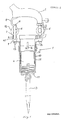
- Figure 1 shows in a partially sectioned side view, a first antivibration arrangement, according to the invention, applied on a chisel hammer,
- Figure 2 shows in partial section an antivibration arrangement according to the invention,
- Figure 3 shows from above a component utilized in the means according to Figure 1,
- Figure 4 shows a side view of the component seen from above in Figure 3,
- Figure 5 shows a section through an antivibration element suitable for use in the arrangement according to the invention,
- Figure 6 shows a side view of the antivibration element shown in Figure 5,
- Figure 7 shows a side view of a component included in the antivibration element according to the invention shown in Figures 5 and 6, and
- Figure 8 shows a section through the component shown in Figure 7.
- The equipment shown in Figure 1 consists of a
chisel hammer 1, comprising ahandle 2, a chisel tool 3 and amachine housing 4, holding the drive means of the chisel tool 3. Said drive means may comprise a piston operated by blast air, the blast air being supplied through apipe 5. The drive means itself is conventional and is not described further here, particularly since the antivibration arrangement is not limited to the application shown and can be used for many types of vibration-generating gear. - The upper part of the
motor housing 4 is provided with radially projecting flanges 6 withguide holes 7, each lined with a flange bushing 47 of low-friction material, taking acontrol bolt 8. The control bolt comprises a screw-tappedportion 10 which is screwed into a correspondingly tapped hole either directly in thehandle 2 or in a connecting element 11 attached to the handle, and ahead 9 on the lower side of the flanges 6. The axial movement of thehandle 2 in relation to themachine housing 4 is thus limited. A number ofantivibration inserts 12 are arranged between thehandle 2 and the upper side of the flanges 6, one insert for eachbolt 8. Theinserts 12 are hollow, allowing thebolts 8 to pass through and abut the upper side of the flanges 6 and against thehandle 2 or the connecting element 11 attached to thehandle 2. Thehandle 2 is thus buffered with respect to themachine housing 4. - An
upper sleeve 14 is arranged around the upper part of themachine housing 4, in order to protect the hand not holding thehandle 2, but gripping themachine housing 4. Alower sleeve 15 is removably joined to theupper sleeve 14, via abayonet catch 16, for instance. Thelower sleeve 15 surrounds the lower part of themachine housing 4 and can be released from theupper sleeve 14 to allow access to acatch 17 for removing the chisel 3 from the upper part of theequipment 1. Theupper sleeve 14 is provided with aflange section 18 having a number of axial through-holes. The number of holes is the same as the number ofbolts 8. Eachbolt head 9 is provided with a tapped hole into which a screw 13 with head is screwed, thus firmly securing theupper sleeve 14 to thebolts 8 and thus to thehandle 2. Thesleeves antivibration elements 12 absorbing the vibrations transmitted from machine housing to handle 2. - A tool without vibration absorption can thus be simply and relatively inexpensively reconstructed to provide satisfactory protection against vibration. Furthermore, it takes little space since the same antivibration element is used for the
sleeves handle 2. To prevent vibrations being transmitted radially to thelower sleeve 15, the machine housing may be provided with an antivibration ring 20 which prevents thelower sleeve 15 from coming into direct contact with themachine housing 4. The antivibration ring 20 is manufactured of a suitably absorbent material such as rubber, and alayer 19 of friction-reducing material such as polytetrafluorethylene, may suitably be arranged between ring 20 andlower sleeve 15, to prevent unnecessary friction between these parts. - Figures 3 and 4 show in more detail the sleeve arrangement used to isolate the
machine housing 4. Figure 3 is a view from above and Figure 4 a side view. Theflange 18 connected to theupper sleeve 14 is here in the form of two flanges 18a and 18b, flange 18b being provided with two attachment holes and flange 18a being provided with one hole. Obviously, thepart 18 may equally well be an unbroken, peripheral flange, or it may be divided into several flanges, one for eachbolt 8, for instance. - Neither is it absolutely necessary to utilize all the
bolts 8 to secure theupper sleeve 14. Figures 3 and 4 also show the bayonet catch used. Three catches are utilized here. They are of conventional type consisting of adowel 21 attached to theupper sleeve 14 and cooperating with anangled slit 22 in the lower sleeve. Other equivalent means such as a screw joint may of course be used instead of the bayonet catch, thelower sleeve 15 being screwed onto theupper sleeve 14. - The invention is naturally not limited to the double-sleeve embodiment shown here. The
lower sleeve 15 may be omitted and the single,upper sleeve 14 being allowed to extend to cover themachine housing 4. Furthermore, the antivibration element need not necessarily be in the form of a sleeve totally surrounding themachine housing 4. For some applications it may be quite sufficient to use a support element which only partially covers thehousing 4, such as the side of the housing the operator uses to align and support the equipment. - It is no doubt obvious that the invention is not limited to an antivibration arrangement as shown in Figure 1. Another example is shown in Figure 2 where the antivibration member comprises a
single element 23 arranged centrally betweenmachine housing 4 andhandle 2. Theantivibration element 23 consists here of a pneumatic ring comprising acavity 24 which can be pressurized by a suitable medium, e.g. air, via achannel 26. Thechannel 26 contains valve elements, not shown, ensuring that the medium remains in thecavity 24 or permits it to be withdrawn to lower the pressure. Theantivibration element 23 includes a central guide consisting of aninner guide ring 27 and anouter guide ring 28, theinner guide ring 27 being slidable inside theouter guide ring 28. An axial key located in axial slots in each guide ring, for instance, ensures that therings antivibration element 23 is also provided withresilient walls 29, of rubber, for instance. Since the pressure in thecavity 24 of theelement 23 can be altered, the absorption properties can easily be adjusted to the existing requirements. Furthermore, arranging control centrally in theelement 23, offers a compact arrangement which takes very little space, especially in radial direction. As in the embodiment shown in Figure 1, twosleeves machine housing 4. However, thesleeve 14 is different from that in the first example and is here in direct contact with thehandle 2. The upper part of theupper sleeve 14 is therefore provided with acircular flange 30 facing radially inwards and clamped between the upper portion of theguide ring 27 and thehandle 2.Screws 25 are used to secure thehandle 2 in theinner guide ring 27, thus securing theflange 30 of theupper sleeve 14 between theinner guide ring 27 and thehandle 2. Theupper sleeve 14 hangs down from theflange 30, close to theantivibration element 23, its lower part surrounding a part of themachine housing 4. Thelower sleeve 15 is then screwed onto the lower part of theupper sleeve 14. Thesleeve 14 may of course be similar to that in the first embodiment, and be secured to control bolts radially surrounding thecentral antivibration element 23. In this case, of course, theelement 23 requires no central guide. - Conversely, the
upper sleeve 14 in the first embodiment may be similar to that described above and may be secured directly to the handle. Theupper sleeve 14 must then be adjusted to the rest of the arrangement and will be considerably larger in diameter than in the second embodiment, so that it can surround thebolts 8. - The embodiments described by way of example apply to chisel hammers. However, the invention can of course be used in all fields where equipment generating vibration is used. Examples are power-driven equipment for sheet-metal working, fettling in the casting industry, weld finishing, in the building industry, stone-work and sculpture, road-building, ship-building, forrestry, etc.
- Figures 5 - 8 show an embodiment of an antivibration element particularly suitable for use in manual equipment to achieve the vibration protection described, since it absorbs not only vibrations in the axial direction of the equipment but also vibrations transverse to this direction. With the aid of a suitable number of antivibration elements, the handle and the protective element at least partially surrounding the machine housing, are connected to the machine housing, the vibration from the housing thus being absorbed by these elements. An extremely important advantage inherent in the elements shown in these figures is that a single unit provides absorption of vibrations in two directions perpendicular to each other, the absorption in one direction being independent of the absorption in the other direction. Furthermore, the level of absorption can be adjusted exactly to the prevailing requirements.
- The
unit 31 shown in Figures 5 and 6, comprises a firstresilient element 32 of rubber, substantially in the form of a ring. Ahole 33 extends transversely through theresilient element 32, perpendicular to the cylinder axis. Each end of the hole at the outer surface is provided with asleeve 34 of low-friction material, such as polytetrafluorethylene. Thanks to thesleeves 34, the firstresilient element 32 is slidable on abolt 35 provided with a head, which acts as guide to the resilient element and prevents it from becoming deformed across its direction of spring action. The tappedend 36 of thebolt 35 is screwed into a slidingblock 37 which can move counter to twosprings 38, transversely to the axial direction of thebolt 35, inside acasing 39. The slidingblock 37, casing 39 and twosprings 38 form a second resilient element. Thecasing 39 comprises twoattachment flanges 40 provided with holes, with the aid of which the antivibration unit is secured. An upper and a lowerangular element 42 is vulcanized to the upper and lower side, respectively, of the firstresilient element 32. Eachangular element slot rubber element 32. The twoangular elements attachment element 45 passing through theslots plate 46 of low-friction material such as polytetrafluorethylene is arranged on the dowel between the free flanges of theangular elements - The
guide bolt 35 can be used to give the firstresilient element 32 suitable pre-stressing. The shorter the bolt length, the higher will be the pre-stressing. Theresilient element 32 may also be pre-stressed by having theslots antivibration unit 31, theattachment flanges 40 are secured to one element, for instance the machine housing in a power-driven manual equipment, while the other element, for instance the handle, is screwed by an attachment bolt into the tapped central hole of theattachment element 45. - An essential advantage of the
antivibration unit 31 is that the spring action of the firstresilient element 32 is independent of the direction of load. - In the embodiment shown, the
bolt 35 is primarily responsible for the guidance, but this could also be taken care of by only the angular elements sliding against each other. If thecontrol bolt 35 is omitted, the elements which are then responsible for guidance must of course be dimensioned accordingly. The first resilient element can then be secured to the second resilient element by means of a tapped dowel projecting from the flange vulcanized to the lowerangular element 42, said dowel being screwed into the slidingblock 37. Instead ofangular elements resilient element 32. Each yoke element comprises free shanks provided with slits, each extending along the firstresilient element 32. The portion between the shanks is vulcanized to the first resilient element. The free shanks of the lower yoke element are slidably secured to the free shanks of the upper yoke element by an attachment and guide element, in the same way as the free flanges of theangular elements
Claims (15)
Applications Claiming Priority (2)
| Application Number | Priority Date | Filing Date | Title |
|---|---|---|---|
| SE8602165 | 1986-05-12 | ||
| SE8602165A SE460266B (en) | 1986-05-12 | 1986-05-12 | VIBRATION PROTECTION IN AN ENGINE-DRIVEN VIBRATION DRIVE HAND TOOL |
Publications (2)
| Publication Number | Publication Date |
|---|---|
| EP0246212A2 true EP0246212A2 (en) | 1987-11-19 |
| EP0246212A3 EP0246212A3 (en) | 1989-05-24 |
Family
ID=20364508
Family Applications (1)
| Application Number | Title | Priority Date | Filing Date |
|---|---|---|---|
| EP87850151A Withdrawn EP0246212A3 (en) | 1986-05-12 | 1987-05-08 | Protection against vibrations at a motor driven vibration generating handtool |
Country Status (2)
| Country | Link |
|---|---|
| EP (1) | EP0246212A3 (en) |
| SE (1) | SE460266B (en) |
Cited By (6)
| Publication number | Priority date | Publication date | Assignee | Title |
|---|---|---|---|---|
| GB2237528A (en) * | 1989-10-31 | 1991-05-08 | Breakers As | Vibration-damped hydraulic hammer |
| EP0680399A1 (en) * | 1993-01-27 | 1995-11-08 | Lord Corporation | Vibration isolator for hand-held vibrating devices |
| US5839517A (en) * | 1993-01-27 | 1998-11-24 | Lord Corporation | Vibration isolator for hand-held vibrating devices |
| ES2200655A1 (en) * | 2001-11-20 | 2004-03-01 | Kaaz Corp | Vibratory harvest for fruit trees. (Machine-translation by Google Translate, not legally binding) |
| GB2429257A (en) * | 2005-08-20 | 2007-02-21 | Bryar Group Ltd | An anti-vibration unit for a petrol impact wrench and an impact wrench incorporating such a unit |
| IT202100005933A1 (en) * | 2021-03-12 | 2022-09-12 | Cembre Spa | IMPACT SCREWDRIVER |
Citations (9)
| Publication number | Priority date | Publication date | Assignee | Title |
|---|---|---|---|---|
| GB191220091A (en) * | 1912-09-03 | 1913-09-03 | George Lawson Robertson | Improvements in Pneumatic Hammers. |
| US1667271A (en) * | 1925-05-16 | 1928-04-24 | Chicago Pneumatic Tool Co | Handle attachment for drills |
| US1792894A (en) * | 1928-04-03 | 1931-02-17 | Chicago Pneumatic Tool Co | Manually-supported power tool |
| US2109964A (en) * | 1935-06-05 | 1938-03-01 | Ingersoll Rand Co | Regulating device for centrifugal compressors |
| DE1503193B1 (en) * | 1964-08-13 | 1970-02-19 | Erich Hahn | Pneumatic impact tool |
| GB1462659A (en) * | 1974-05-20 | 1977-01-26 | Vni I Pk I | Pneumatic hammers |
| FR2504440A1 (en) * | 1981-04-28 | 1982-10-29 | Permon Np | |
| GB2098121A (en) * | 1981-05-07 | 1982-11-17 | Mo Vysshee Teknicheskoe Uchili | Shock-absorbing pneumatic percussive tool |
| EP0207034A1 (en) * | 1985-06-19 | 1986-12-30 | Eskil Sundström | A vibration-absorbing handle |
Family Cites Families (1)
| Publication number | Priority date | Publication date | Assignee | Title |
|---|---|---|---|---|
| US2019964A (en) * | 1933-02-20 | 1935-11-05 | Independent Pneumatic Tool Co | Cushion means for tools |
-
1986
- 1986-05-12 SE SE8602165A patent/SE460266B/en not_active IP Right Cessation
-
1987
- 1987-05-08 EP EP87850151A patent/EP0246212A3/en not_active Withdrawn
Patent Citations (9)
| Publication number | Priority date | Publication date | Assignee | Title |
|---|---|---|---|---|
| GB191220091A (en) * | 1912-09-03 | 1913-09-03 | George Lawson Robertson | Improvements in Pneumatic Hammers. |
| US1667271A (en) * | 1925-05-16 | 1928-04-24 | Chicago Pneumatic Tool Co | Handle attachment for drills |
| US1792894A (en) * | 1928-04-03 | 1931-02-17 | Chicago Pneumatic Tool Co | Manually-supported power tool |
| US2109964A (en) * | 1935-06-05 | 1938-03-01 | Ingersoll Rand Co | Regulating device for centrifugal compressors |
| DE1503193B1 (en) * | 1964-08-13 | 1970-02-19 | Erich Hahn | Pneumatic impact tool |
| GB1462659A (en) * | 1974-05-20 | 1977-01-26 | Vni I Pk I | Pneumatic hammers |
| FR2504440A1 (en) * | 1981-04-28 | 1982-10-29 | Permon Np | |
| GB2098121A (en) * | 1981-05-07 | 1982-11-17 | Mo Vysshee Teknicheskoe Uchili | Shock-absorbing pneumatic percussive tool |
| EP0207034A1 (en) * | 1985-06-19 | 1986-12-30 | Eskil Sundström | A vibration-absorbing handle |
Cited By (9)
| Publication number | Priority date | Publication date | Assignee | Title |
|---|---|---|---|---|
| GB2237528A (en) * | 1989-10-31 | 1991-05-08 | Breakers As | Vibration-damped hydraulic hammer |
| EP0680399A1 (en) * | 1993-01-27 | 1995-11-08 | Lord Corporation | Vibration isolator for hand-held vibrating devices |
| EP0680399A4 (en) * | 1993-01-27 | 1996-01-10 | Lord Corp | Vibration isolator for hand-held vibrating devices. |
| US5839517A (en) * | 1993-01-27 | 1998-11-24 | Lord Corporation | Vibration isolator for hand-held vibrating devices |
| ES2200655A1 (en) * | 2001-11-20 | 2004-03-01 | Kaaz Corp | Vibratory harvest for fruit trees. (Machine-translation by Google Translate, not legally binding) |
| GB2429257A (en) * | 2005-08-20 | 2007-02-21 | Bryar Group Ltd | An anti-vibration unit for a petrol impact wrench and an impact wrench incorporating such a unit |
| IT202100005933A1 (en) * | 2021-03-12 | 2022-09-12 | Cembre Spa | IMPACT SCREWDRIVER |
| EP4056326A1 (en) * | 2021-03-12 | 2022-09-14 | CEMBRE S.p.A. | Impact wrench |
| WO2022190025A1 (en) * | 2021-03-12 | 2022-09-15 | Cembre S.P.A. | Impact tool |
Also Published As
| Publication number | Publication date |
|---|---|
| EP0246212A3 (en) | 1989-05-24 |
| SE8602165L (en) | 1987-11-13 |
| SE460266B (en) | 1989-09-25 |
| SE8602165D0 (en) | 1986-05-13 |
Similar Documents
| Publication | Publication Date | Title |
|---|---|---|
| US4381579A (en) | Handle for a hand-held device | |
| US5692306A (en) | Hand-held working tool | |
| EP1514648B1 (en) | Vibration isolating handle | |
| JPH05208383A (en) | Vibration prevention power tool handle | |
| JP4195125B2 (en) | Drill / chisel device | |
| US20080235913A1 (en) | Handle | |
| US20080148525A1 (en) | Hand power tool with at least one handle | |
| US20050224244A1 (en) | Hand machine tool comprising at least one handle | |
| EP0246212A2 (en) | Protection against vibrations at a motor driven vibration generating handtool | |
| AU3853585A (en) | Percussive "rust" removal tool | |
| PL153240B1 (en) | Vibration damping arrangement for hand tools | |
| JP5984658B2 (en) | Impact tool | |
| US20080190631A1 (en) | Vibration Reduction in Electric Tools | |
| EP0675781A1 (en) | A vibration-free grinding machine | |
| JP4248979B2 (en) | Anti-vibration handle | |
| GB2285007A (en) | Hammer drill | |
| KR960005001Y1 (en) | Breaker chisel assembly | |
| GB2237528A (en) | Vibration-damped hydraulic hammer | |
| JP5537335B2 (en) | Dust collector | |
| JP4672033B2 (en) | Anti-vibration handle | |
| JP4338469B2 (en) | Portable work machine | |
| SU575216A1 (en) | Vibration-damping device to working tool of percussive power-driven hand tools | |
| US20220281091A1 (en) | Side handle assembly for power tool | |
| SU716805A1 (en) | Vibration-protected device for percussive-action hand-operated tools | |
| RU2058880C1 (en) | Device for holding working tool in hand impact machines |
Legal Events
| Date | Code | Title | Description |
|---|---|---|---|
| PUAI | Public reference made under article 153(3) epc to a published international application that has entered the european phase |
Free format text: ORIGINAL CODE: 0009012 |
|
| AK | Designated contracting states |
Kind code of ref document: A2 Designated state(s): AT BE CH DE ES FR GB IT LI NL |
|
| PUAL | Search report despatched |
Free format text: ORIGINAL CODE: 0009013 |
|
| AK | Designated contracting states |
Kind code of ref document: A3 Designated state(s): AT BE CH DE ES FR GB IT LI NL |
|
| 17P | Request for examination filed |
Effective date: 19891121 |
|
| ITF | It: translation for a ep patent filed |
Owner name: PROPRIA PROTEZIONE PROPR. IND. |
|
| 17Q | First examination report despatched |
Effective date: 19910425 |
|
| STAA | Information on the status of an ep patent application or granted ep patent |
Free format text: STATUS: THE APPLICATION IS DEEMED TO BE WITHDRAWN |
|
| 18D | Application deemed to be withdrawn |
Effective date: 19911106 |