EP0245853A2 - Lichtdurchlassendes Material für Anzeigeleuchten - Google Patents
Lichtdurchlassendes Material für Anzeigeleuchten Download PDFInfo
- Publication number
- EP0245853A2 EP0245853A2 EP87106951A EP87106951A EP0245853A2 EP 0245853 A2 EP0245853 A2 EP 0245853A2 EP 87106951 A EP87106951 A EP 87106951A EP 87106951 A EP87106951 A EP 87106951A EP 0245853 A2 EP0245853 A2 EP 0245853A2
- Authority
- EP
- European Patent Office
- Prior art keywords
- light
- transmitting
- layer
- color
- indicator
- Prior art date
- Legal status (The legal status is an assumption and is not a legal conclusion. Google has not performed a legal analysis and makes no representation as to the accuracy of the status listed.)
- Withdrawn
Links
Images

Classifications
-
- F—MECHANICAL ENGINEERING; LIGHTING; HEATING; WEAPONS; BLASTING
- F21—LIGHTING
- F21S—NON-PORTABLE LIGHTING DEVICES; SYSTEMS THEREOF; VEHICLE LIGHTING DEVICES SPECIALLY ADAPTED FOR VEHICLE EXTERIORS
- F21S43/00—Signalling devices specially adapted for vehicle exteriors, e.g. brake lamps, direction indicator lights or reversing lights
- F21S43/20—Signalling devices specially adapted for vehicle exteriors, e.g. brake lamps, direction indicator lights or reversing lights characterised by refractors, transparent cover plates, light guides or filters
- F21S43/255—Filters
-
- F—MECHANICAL ENGINEERING; LIGHTING; HEATING; WEAPONS; BLASTING
- F21—LIGHTING
- F21W—INDEXING SCHEME ASSOCIATED WITH SUBCLASSES F21K, F21L, F21S and F21V, RELATING TO USES OR APPLICATIONS OF LIGHTING DEVICES OR SYSTEMS
- F21W2111/00—Use or application of lighting devices or systems for signalling, marking or indicating, not provided for in codes F21W2102/00 – F21W2107/00
- F21W2111/02—Use or application of lighting devices or systems for signalling, marking or indicating, not provided for in codes F21W2102/00 – F21W2107/00 for roads, paths or the like
Definitions
- the present invention relates to a light-transmitting material which may be employed as a cover for a winker lamp, brake lamp or the like to be mounted on an automobile, or as an outer surface member of the indicating sections of illuminated indicators or decorative means employing light which are provided on household appliances, data communication equipment or the like.
- a winker lamp, brake lamp or the like of an automobile generally has a white-light emitting lamp provided therein and a light-transmitting cover colored orange or red, and is arranged such that, when the lamp is turned on, light emitted therefrom passes through the colored light-transmitting cover and light Having the color of the cover is thereby emitted to transmit predetermined information to the surroundings.
- these lamps are desirable for these lamps to be such that, when the light source is in the OFF state, the color of the external surface of the lamp is the same as the color of the body or exterior trim part of the automobile in the vicinity of the lamp concerned and, hence, is different from the above-described information transmitting color, such as red or orange, and that light having a desired information transmitting color is emitted only when the light source is turned ON.
- the lamps used in a variety of illuminated indicators and decorative means provided in, for example, the console box which is disposed at the driver's seat of an automobile.
- the present invention provides a light-transmitting material comprising a light-transmitting layer which transmits light and has a light color, and a light-shielding layer provided on the reverse surface of the light-transmitting layer.
- the light-shielding layer is composed of a light-shielding portion which transmits substantially no light and a light-transmitting portion which is defined by minute slits, a mesh with minute apertures, or the like, the apertures being provided at a predetermined density.
- the light-shielding portion can be given a deep color using a metal coating or an organic coating.
- the light-transmitting material according to the present invention is employed as an outer surface member of an illuminated indicator, when the indicator is in the OFF state, its exterior appears as a composite color which is composed of the light color of the light-transmitting layer and the color of the light-shielding layer.
- the light-transmitting layer is light blue and the light-shielding portion of the light-shielding layer is blue
- the exterior assumes a deep blue color
- the light-transmitting layer is light blue as in the case of the above and the light-shielding portion is red
- the exterior of the indicator when in the OFF state appears to be reddish purple.
- the color of the light which is emitted from the inside of the indicator when turned on i.e., the color of light from the light source, or the color of light from the light source when it has passed through a predetermined filter
- the light passing through the light-transmitting portion of the light-shielding layer and the light-transmitting layer reaches the surface portion of the indicator without being strongly affected by the light color of the light-transmitting layer, that is, the color of light reaching the surface portion is close to the color of light emitted from the light source, so that the indicating portion is illuminated with light having a color which is different from the color of the exterior of the indicator when in the OFF state. Accordingly, the exterior of the indicator when in the ON state assumes a color which is different from that of the indicator when in the OFF state.
- the color of the exterior of the indicator when in the normal OFF state can be selected almost regardless of the color of the exterior of the indicator when in the ON state (for transmitting predetermined information to the observer). Accordingly, the indicator concerned and surrounding portions can generally be designed free from constraints. Further, a change in color of the exterior as a result of switching the indicator from the OFF state to the ON state gives a very strong impression to the observer and therefore attracts his attention to the indicator. Accordingly, the indicator is capable of exhibiting a superior information transmitting function.
- the light-transmitting portion of the light-shielding layer is formed in the shape of a desired character, pattern or the like, when the indicator is turned on, a pattern of a color which is completely different from the color of the exterior suddenly appears, which effectively attracts the observer's attention.
- the difference between the color of the illuminated character, pattern or the like when the indicator is in the ON state and the composite color of the background thereof represents an excellent visual design feature by its use of a sharp contrast and advantageous effects. Since the light-transmitting material according to the present invention has the light-shielding layer having the above-described structure, the interior of an illuminated indicator employing such a light-transmitting material can be made completely invisible from the outside when the indicator is in the normal state.
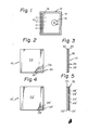
- Fig. 1 shows a basic arrangement of an illuminated indicator 12 such as a winker lamp, a brake lamp or an indicator in a console box provided in an automobile, the indicator 12 employing as its outer surface member or cover a light-transmitting material 10 according to a first embodiment of the present invention.
- an illuminated indicator 12 such as a winker lamp, a brake lamp or an indicator in a console box provided in an automobile
- the indicator 12 employing as its outer surface member or cover a light-transmitting material 10 according to a first embodiment of the present invention.
- the indicator 12 has a casing 14, a lamp 16 as a light source and a color filter 18 which is disposed on the inner side of the light-transmitting material (surface member) 10.
- the filter 18 is defined by an orange filter which transmits only orange light.
- the light-transmitting material 10 consists of an outer light-transmitting layer 22 which is only slightly tinted with such light colors as blue, red or white and an inner light-shielding layer 24 which is formed on the reverse surface of the light-transmitting layer 22.
- the light-shielding layer 24 has a light-shielding portion 26 which is made of a metal or a non-light transmitting paint and which transmits substantially no light, and a light-transmitting portion 28 which is defined by a multiplicity of apertures which are formed in the light-shielding portion 26 at a predetermined density.
- the light-transmitting layer 22 is defined by a colored sheet or film made of acrylic, polyester, polycarbonate, nylon or other synthetic resins, or colored glass.
- the light-transmitting layer 22 does not necessarily need to be completely transparent so long as it transmits light.
- the apertures defining the light-transmitting portion 28 are formed in the light-shielding layer 24 in the form of a mesh, they may be shaped and arranged as desired.
- the apertures may be defined by slits.
- the light-shielding layer 24 may be formed by any of the following various methods. (1) A metal layer is formed on the reverse surface of the light-transmitting layer 22 by vacuum deposition or sputtering, and a mask which corresponds to the pattern of the light-shielding portion 26 of the light-shielding layer 24 is formed on the metal layer by means of pattern printing or a photoresist technique. Then, the non-masked portion is removed by etching to define the light-transmitting portion 28.
- the reverse surface of the light-transmitting layer 22 is first colored by pattern printing, and a metal layer is then formed thereon. Thereafter, a mask is formed on the metal layer by pattern printing or a photoresist technique, and the non-masked portion is removed by etching.
- Figs. 4 and 5 show in combination a light-transmitting material 10' in accordance with a second embodiment of the present invention.
- this light-transmitting material 10' consists of two plate materials 30 and 32.
- the plate material 30 is a light-transmitting material having a light color which is similar to the light-transmitting layer 22 in the first embodiment, and defines a light-transmitting layer 22' in the second embodiment.
- the second plate material 32 is defined by a light-transmitting sheet or film made of acrylic, polyester, polycarbonate, nylon or other synthetic resins, or a light-transmitting sheet of glass.
- a light-shielding layer 24' is formed on the obverse surface of the plate material 32 by a method similar to that employed to form the light-shielding layer 24 in the first embodiment.
- an illuminated indicator 12 employing the above-described light-transmitting material 10 or 10' as its surface member
- the exterior of the indicator 12 assumes a color representing a combination of the color of the light-transmitting layer 22 or 22' of the light-transmitting material 10 or 10' and the color of the outer surface of the light-shielding layer 24 or 24'. If, for example, the light-transmitting layer 22 or 22' is light blue and the outer surface of the light-shielding layer 24 or 24' is deep blue, the exterior of the indicator 12 when in the OFF state appears to be a deep blue.
- the external light is prevented from entering the interior of the indicator 12 by means of the light-shielding layer 24 or 24', there is substantially no risk of the interior of the indicator 12 being seen. If the size of the apertures provided in the light-shielding layer 24 or 24' is made sufficiently small, they can hardly be seen unless special attention is given.
- the light emitted from the lamp 16 passes through the filter 18 and is transmitted by the light-transmitting portion 28 or 28' of the light-shielding layer 24 or 24' and the light-transmitting layer 22 or 22' to the outside. Accordingly, light of a predetermined color, for example, orange light in the case of an orange filter 18, is transmitted by the light-transmitting portion 28 or 28' and the light-transmitting layer 22 or 22'. Since the light-transmitting layer 22 or 22 1 is only slightly tinted as described above, the color of light which is transmitted therethrough is only slightly changed; in the case, for example, of an orange filter 18, the orange light is emitted to the outside with substantially no change in color.
- a predetermined color for example, orange light in the case of an orange filter 18
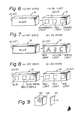
- Figs. 6(a) and 6(b) show in combination an indicator 12 which is designed to be capable of emitting three different kinds of light by utilizing the above-described basic illuminated indicator arrangement. More specifically, the outer light-transmitting layer made of the light-transmitting material 10 of this indicator 12 is slightly tinted black, the light-shielding layer of the material 10 is formed from a black paint, and the light-transmitting portion in the light-shielding layer is defined by three square regions which are spaced apart from each other.
- the lamp provided inside the indicator 12 is defined by a lamp emitting white light, and three filters, that is, orange, red and transparent filters, are provided in that order from the right-hand side as viewed in the figure in correspondence with the three light-transmitting regions, respectively. It should be noted that the transparent filter may be omitted as desired.
- the indicator 12 when the indicator 12 is in the OFF state (shown in Fig. 6(a)), the surface thereof assumes a deep black color, whereas when the indicator 12 is in the ON state (shown in Fig. 6(b)), orange, red and white rays of light are emitted from the three light-transmitting regions in that order from the right to the left as viewed in the f.igure.
- Figs. 7(a) and 7(b) show in combination an illuminated indicator 12 having an arrangement similar to that of the indicator 12 shown in Figs. 6(a) and 6(b).
- the indicator 12 shown in Figs. 7(a) and 7(b) mainly differs from that shown in Figs. 6(a) and 6(b) in that the light-transmitting regions in the light-shielding layer are arranged in the shape of A, B and C so as to display desired patterns.
- Figs. 8(a) and 8(b) show in combination still another example of an application of the present invention.
- the indicator 12 in this example is arranged such that the light-transmitting layer 22 of the light-transmitting material 10 is colored light blue and three light-transmitting regions provided in the light-shielding layer 24 are respectively colored green, red and blue in that order from the right to the left as viewed in the figures, so that, when the light source is in the OFF state, the light-transmitting regions appear to be blue-green, red-purple and blue, respectively, from the right to the left.
- the filter of this indicator 12 is defined by a red filter. Accordingly, when the indicator 12 is turned on, the external portions which appear to be blue-green, red-purple and blue, respectively, when the device is in the OFF state are all illuminated with red light. It should be noted that in this case a lamp which emits red light may be employed in place of the white-light emitting lamp to eliminate the need to employ a red filter.
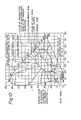
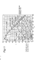
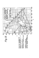
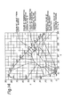
- An illuminated indicator according to the present invention and a conventional illuminated indicator of this type having a structure such as that shown in Fig. 9 were tested under the following conditions.
- the light-transmitting material had the structure shown in Figs. 4 and 5.
- the light-transmitting layer 22' was defined by a light-transmitting material colored light blue, and the light-shielding layer 24' was produced in such a manner that a metal coating was formed on the surface of the plate material 32 by means of sputtering and a pattern of a light-shielding portion was printed on the metal coating with deep blue ink to form a mask, and the metal coating was then subjected to etching to form light-transmitting portions.
- the surface wall material 40 of the indicator shown in Fig. 9 was made by coating a transparent acrylic sheet with a blue paint.
- the lamps 16 and 42 (emitting orange light) of both the indicators were defined by tungsten-filament lamps and the filters 18 and 44 were defined by orange filters.
- the results of the test are shown in Table 1 below.
- "transmittance” is the transmittance of the light-transmitting material 10' of the indicator according to the present invention and that of light transmitted by the surface wall material 40 of the indicator shown in Fig. 9, and "illuminance” means the illuminance of the transmitted light.
- the two indicators were compared with each other under conditions where the illuminance of the transmitted light was set at the same level.
- the filter was removed from each indicator, and a tungsten-filament lamp alone was employed for the light source.
- the two indicators were compared with each other under conditions where the chromaticity of the transmitted light was set to be the same.
- the light-transmitting material according to the present invention permits the color of light transmitted thereby to be close to the color of light from the light source without being affected by the color of the external surface. Accordingly, this light-transmitting material is capable of meeting the requirements described in the section entitled "Background of the Invention".
Landscapes
- Engineering & Computer Science (AREA)
- General Engineering & Computer Science (AREA)
- Illuminated Signs And Luminous Advertising (AREA)
- Optical Filters (AREA)
- Surface Treatment Of Optical Elements (AREA)
Applications Claiming Priority (2)
| Application Number | Priority Date | Filing Date | Title |
|---|---|---|---|
| JP109776/86 | 1986-05-14 | ||
| JP61109776A JPS62266587A (ja) | 1986-05-14 | 1986-05-14 | 発光性表示装置用の透光性材 |
Publications (2)
| Publication Number | Publication Date |
|---|---|
| EP0245853A2 true EP0245853A2 (de) | 1987-11-19 |
| EP0245853A3 EP0245853A3 (de) | 1989-07-12 |
Family
ID=14518936
Family Applications (1)
| Application Number | Title | Priority Date | Filing Date |
|---|---|---|---|
| EP87106951A Withdrawn EP0245853A3 (de) | 1986-05-14 | 1987-05-13 | Lichtdurchlassendes Material für Anzeigeleuchten |
Country Status (2)
| Country | Link |
|---|---|
| EP (1) | EP0245853A3 (de) |
| JP (1) | JPS62266587A (de) |
Cited By (3)
| Publication number | Priority date | Publication date | Assignee | Title |
|---|---|---|---|---|
| EP0622585A1 (de) * | 1993-04-29 | 1994-11-02 | Illinois Tool Works Inc. | Bildtragende Anordnungen |
| EP1253043A3 (de) * | 2001-04-24 | 2006-10-18 | Ichikoh Industries, Ltd. | Leuchteneinrichtung für Fahrzeuge |
| CN115243888A (zh) * | 2020-04-02 | 2022-10-25 | 日写株式会社 | 装饰片及显示装置 |
Families Citing this family (6)
| Publication number | Priority date | Publication date | Assignee | Title |
|---|---|---|---|---|
| JPH0192626U (de) * | 1987-12-14 | 1989-06-16 | ||
| JPH0192625U (de) * | 1987-12-14 | 1989-06-16 | ||
| JPH0192624U (de) * | 1987-12-14 | 1989-06-16 | ||
| JPH02104389U (de) * | 1989-02-07 | 1990-08-20 | ||
| JP5214109B2 (ja) * | 2006-02-03 | 2013-06-19 | 富士通モバイルコミュニケーションズ株式会社 | 表示構造を備えた物品 |
| JP5215108B2 (ja) * | 2008-10-03 | 2013-06-19 | ソニーモバイルコミュニケーションズ株式会社 | 表示装置、表示装置の形成方法、キー装置、キー装置の形成方法、電子機器、及び携帯端末装置 |
Family Cites Families (8)
| Publication number | Priority date | Publication date | Assignee | Title |
|---|---|---|---|---|
| US2286201A (en) * | 1939-04-05 | 1942-06-16 | Clair L Farrand | Opaque apertured signal lens |
| US2907249A (en) * | 1956-10-05 | 1959-10-06 | Electro Seal Corp | Lens for signal lights |
| GB1430580A (en) * | 1972-06-28 | 1976-03-31 | Lucas Electrical Ltd | Multicolour warning lamp assemblies |
| FR2409455A1 (fr) * | 1977-11-21 | 1979-06-15 | Frankani Sa | Vitre pour lanterne de signalisation pour vehicules automobiles et lanterne equipee de cette vitre |
| GB1591013A (en) * | 1978-05-30 | 1981-06-10 | Lucas Industries Ltd | High contrast lamp assembly |
| JPS573020U (de) * | 1980-06-06 | 1982-01-08 | ||
| FR2525322B1 (fr) * | 1982-04-20 | 1987-09-04 | Frankani Sa | Lanterne de signalisation pour vehicule automobile |
| JPS59178479A (ja) * | 1983-03-30 | 1984-10-09 | 株式会社東海理化電機製作所 | 表示装置 |
-
1986
- 1986-05-14 JP JP61109776A patent/JPS62266587A/ja active Pending
-
1987
- 1987-05-13 EP EP87106951A patent/EP0245853A3/de not_active Withdrawn
Cited By (3)
| Publication number | Priority date | Publication date | Assignee | Title |
|---|---|---|---|---|
| EP0622585A1 (de) * | 1993-04-29 | 1994-11-02 | Illinois Tool Works Inc. | Bildtragende Anordnungen |
| EP1253043A3 (de) * | 2001-04-24 | 2006-10-18 | Ichikoh Industries, Ltd. | Leuchteneinrichtung für Fahrzeuge |
| CN115243888A (zh) * | 2020-04-02 | 2022-10-25 | 日写株式会社 | 装饰片及显示装置 |
Also Published As
| Publication number | Publication date |
|---|---|
| JPS62266587A (ja) | 1987-11-19 |
| EP0245853A3 (de) | 1989-07-12 |
Similar Documents
| Publication | Publication Date | Title |
|---|---|---|
| US5404133A (en) | Luminous key top | |
| US5117334A (en) | Illuminated indicator gauge | |
| US6318872B1 (en) | Vehicle light meter having two colored layers with ring member dial | |
| US5023756A (en) | Light diffusion box | |
| DE69517877T2 (de) | Durchscheinender Leuchtstoff-Filter für Anzeigefläche | |
| US6534163B1 (en) | Display board and production method therefor | |
| PL192632B1 (pl) | Tablica wskaźników | |
| US5036440A (en) | Illumination type keytop | |
| US5703625A (en) | Illuminated push button display | |
| JPS58172686A (ja) | 「けい」光表示装置 | |
| EP0245853A2 (de) | Lichtdurchlassendes Material für Anzeigeleuchten | |
| US4518225A (en) | Multicolored liquid crystal displays utilizing photoluminescent transflectors and mask | |
| GB2264897A (en) | Greeting card with stained-glass window effect. | |
| US5032711A (en) | Automotive meter | |
| US4968526A (en) | Method for fabricating a key top | |
| US4417411A (en) | Information display device | |
| US2372124A (en) | Sign construction | |
| JP2004038068A (ja) | 表示体用部材、表示体用部材を使用した表示体及び押釦スイッチ構造体 | |
| JP2725703B2 (ja) | エレクトロルミネッセンス光源用フィルタ | |
| JPS5834466Y2 (ja) | 表示装置 | |
| JP3063080B2 (ja) | 表示装置 | |
| JP3026262B1 (ja) | 表示板 | |
| JP2001343258A (ja) | 照明装置 | |
| JPH0922263A (ja) | 表示装置 | |
| SU830590A1 (ru) | Световое табло |
Legal Events
| Date | Code | Title | Description |
|---|---|---|---|
| PUAI | Public reference made under article 153(3) epc to a published international application that has entered the european phase |
Free format text: ORIGINAL CODE: 0009012 |
|
| AK | Designated contracting states |
Kind code of ref document: A2 Designated state(s): DE FR GB IT |
|
| PUAL | Search report despatched |
Free format text: ORIGINAL CODE: 0009013 |
|
| AK | Designated contracting states |
Kind code of ref document: A3 Designated state(s): DE FR GB IT |
|
| STAA | Information on the status of an ep patent application or granted ep patent |
Free format text: STATUS: THE APPLICATION IS DEEMED TO BE WITHDRAWN |
|
| 18D | Application deemed to be withdrawn |
Effective date: 19900113 |
|
| RIN1 | Information on inventor provided before grant (corrected) |
Inventor name: NAKAGAWA, YOSHIO |