EP0245846A2 - Dispositif prothétique et son procédé de fabrication - Google Patents
Dispositif prothétique et son procédé de fabrication Download PDFInfo
- Publication number
- EP0245846A2 EP0245846A2 EP87106896A EP87106896A EP0245846A2 EP 0245846 A2 EP0245846 A2 EP 0245846A2 EP 87106896 A EP87106896 A EP 87106896A EP 87106896 A EP87106896 A EP 87106896A EP 0245846 A2 EP0245846 A2 EP 0245846A2
- Authority
- EP
- European Patent Office
- Prior art keywords
- anchoring
- bone
- pillars
- prosthesis part
- prosthesis
- Prior art date
- Legal status (The legal status is an assumption and is not a legal conclusion. Google has not performed a legal analysis and makes no representation as to the accuracy of the status listed.)
- Granted
Links
Images


Classifications
-
- A—HUMAN NECESSITIES
- A61—MEDICAL OR VETERINARY SCIENCE; HYGIENE
- A61F—FILTERS IMPLANTABLE INTO BLOOD VESSELS; PROSTHESES; DEVICES PROVIDING PATENCY TO, OR PREVENTING COLLAPSING OF, TUBULAR STRUCTURES OF THE BODY, e.g. STENTS; ORTHOPAEDIC, NURSING OR CONTRACEPTIVE DEVICES; FOMENTATION; TREATMENT OR PROTECTION OF EYES OR EARS; BANDAGES, DRESSINGS OR ABSORBENT PADS; FIRST-AID KITS
- A61F2/00—Filters implantable into blood vessels; Prostheses, i.e. artificial substitutes or replacements for parts of the body; Appliances for connecting them with the body; Devices providing patency to, or preventing collapsing of, tubular structures of the body, e.g. stents
- A61F2/02—Prostheses implantable into the body
- A61F2/30—Joints
- A61F2/3094—Designing or manufacturing processes
- A61F2/30942—Designing or manufacturing processes for designing or making customized prostheses, e.g. using templates, CT or NMR scans, finite-element analysis or CAD-CAM techniques
-
- A—HUMAN NECESSITIES
- A61—MEDICAL OR VETERINARY SCIENCE; HYGIENE
- A61F—FILTERS IMPLANTABLE INTO BLOOD VESSELS; PROSTHESES; DEVICES PROVIDING PATENCY TO, OR PREVENTING COLLAPSING OF, TUBULAR STRUCTURES OF THE BODY, e.g. STENTS; ORTHOPAEDIC, NURSING OR CONTRACEPTIVE DEVICES; FOMENTATION; TREATMENT OR PROTECTION OF EYES OR EARS; BANDAGES, DRESSINGS OR ABSORBENT PADS; FIRST-AID KITS
- A61F2/00—Filters implantable into blood vessels; Prostheses, i.e. artificial substitutes or replacements for parts of the body; Appliances for connecting them with the body; Devices providing patency to, or preventing collapsing of, tubular structures of the body, e.g. stents
- A61F2/02—Prostheses implantable into the body
- A61F2/30—Joints
- A61F2/32—Joints for the hip
- A61F2/36—Femoral heads ; Femoral endoprostheses
- A61F2/3662—Femoral shafts
-
- A—HUMAN NECESSITIES
- A61—MEDICAL OR VETERINARY SCIENCE; HYGIENE
- A61B—DIAGNOSIS; SURGERY; IDENTIFICATION
- A61B17/00—Surgical instruments, devices or methods, e.g. tourniquets
- A61B17/56—Surgical instruments or methods for treatment of bones or joints; Devices specially adapted therefor
- A61B17/58—Surgical instruments or methods for treatment of bones or joints; Devices specially adapted therefor for osteosynthesis, e.g. bone plates, screws, setting implements or the like
- A61B17/68—Internal fixation devices, including fasteners and spinal fixators, even if a part thereof projects from the skin
- A61B17/82—Internal fixation devices, including fasteners and spinal fixators, even if a part thereof projects from the skin for bone cerclage
-
- A—HUMAN NECESSITIES
- A61—MEDICAL OR VETERINARY SCIENCE; HYGIENE
- A61F—FILTERS IMPLANTABLE INTO BLOOD VESSELS; PROSTHESES; DEVICES PROVIDING PATENCY TO, OR PREVENTING COLLAPSING OF, TUBULAR STRUCTURES OF THE BODY, e.g. STENTS; ORTHOPAEDIC, NURSING OR CONTRACEPTIVE DEVICES; FOMENTATION; TREATMENT OR PROTECTION OF EYES OR EARS; BANDAGES, DRESSINGS OR ABSORBENT PADS; FIRST-AID KITS
- A61F2/00—Filters implantable into blood vessels; Prostheses, i.e. artificial substitutes or replacements for parts of the body; Appliances for connecting them with the body; Devices providing patency to, or preventing collapsing of, tubular structures of the body, e.g. stents
- A61F2/02—Prostheses implantable into the body
- A61F2/30—Joints
- A61F2/30767—Special external or bone-contacting surface, e.g. coating for improving bone ingrowth
-
- A—HUMAN NECESSITIES
- A61—MEDICAL OR VETERINARY SCIENCE; HYGIENE
- A61F—FILTERS IMPLANTABLE INTO BLOOD VESSELS; PROSTHESES; DEVICES PROVIDING PATENCY TO, OR PREVENTING COLLAPSING OF, TUBULAR STRUCTURES OF THE BODY, e.g. STENTS; ORTHOPAEDIC, NURSING OR CONTRACEPTIVE DEVICES; FOMENTATION; TREATMENT OR PROTECTION OF EYES OR EARS; BANDAGES, DRESSINGS OR ABSORBENT PADS; FIRST-AID KITS
- A61F2/00—Filters implantable into blood vessels; Prostheses, i.e. artificial substitutes or replacements for parts of the body; Appliances for connecting them with the body; Devices providing patency to, or preventing collapsing of, tubular structures of the body, e.g. stents
- A61F2/02—Prostheses implantable into the body
- A61F2/30—Joints
- A61F2/3094—Designing or manufacturing processes
-
- A—HUMAN NECESSITIES
- A61—MEDICAL OR VETERINARY SCIENCE; HYGIENE
- A61F—FILTERS IMPLANTABLE INTO BLOOD VESSELS; PROSTHESES; DEVICES PROVIDING PATENCY TO, OR PREVENTING COLLAPSING OF, TUBULAR STRUCTURES OF THE BODY, e.g. STENTS; ORTHOPAEDIC, NURSING OR CONTRACEPTIVE DEVICES; FOMENTATION; TREATMENT OR PROTECTION OF EYES OR EARS; BANDAGES, DRESSINGS OR ABSORBENT PADS; FIRST-AID KITS
- A61F2/00—Filters implantable into blood vessels; Prostheses, i.e. artificial substitutes or replacements for parts of the body; Appliances for connecting them with the body; Devices providing patency to, or preventing collapsing of, tubular structures of the body, e.g. stents
- A61F2/02—Prostheses implantable into the body
- A61F2/30—Joints
- A61F2/46—Special tools or methods for implanting or extracting artificial joints, accessories, bone grafts or substitutes, or particular adaptations therefor
- A61F2/4644—Preparation of bone graft, bone plugs or bone dowels, e.g. grinding or milling bone material
-
- A—HUMAN NECESSITIES
- A61—MEDICAL OR VETERINARY SCIENCE; HYGIENE
- A61F—FILTERS IMPLANTABLE INTO BLOOD VESSELS; PROSTHESES; DEVICES PROVIDING PATENCY TO, OR PREVENTING COLLAPSING OF, TUBULAR STRUCTURES OF THE BODY, e.g. STENTS; ORTHOPAEDIC, NURSING OR CONTRACEPTIVE DEVICES; FOMENTATION; TREATMENT OR PROTECTION OF EYES OR EARS; BANDAGES, DRESSINGS OR ABSORBENT PADS; FIRST-AID KITS
- A61F2/00—Filters implantable into blood vessels; Prostheses, i.e. artificial substitutes or replacements for parts of the body; Appliances for connecting them with the body; Devices providing patency to, or preventing collapsing of, tubular structures of the body, e.g. stents
- A61F2/02—Prostheses implantable into the body
- A61F2/28—Bones
- A61F2002/2835—Bone graft implants for filling a bony defect or an endoprosthesis cavity, e.g. by synthetic material or biological material
-
- A—HUMAN NECESSITIES
- A61—MEDICAL OR VETERINARY SCIENCE; HYGIENE
- A61F—FILTERS IMPLANTABLE INTO BLOOD VESSELS; PROSTHESES; DEVICES PROVIDING PATENCY TO, OR PREVENTING COLLAPSING OF, TUBULAR STRUCTURES OF THE BODY, e.g. STENTS; ORTHOPAEDIC, NURSING OR CONTRACEPTIVE DEVICES; FOMENTATION; TREATMENT OR PROTECTION OF EYES OR EARS; BANDAGES, DRESSINGS OR ABSORBENT PADS; FIRST-AID KITS
- A61F2/00—Filters implantable into blood vessels; Prostheses, i.e. artificial substitutes or replacements for parts of the body; Appliances for connecting them with the body; Devices providing patency to, or preventing collapsing of, tubular structures of the body, e.g. stents
- A61F2/02—Prostheses implantable into the body
- A61F2/30—Joints
- A61F2002/30001—Additional features of subject-matter classified in A61F2/28, A61F2/30 and subgroups thereof
- A61F2002/30108—Shapes
- A61F2002/30199—Three-dimensional shapes
- A61F2002/30224—Three-dimensional shapes cylindrical
-
- A—HUMAN NECESSITIES
- A61—MEDICAL OR VETERINARY SCIENCE; HYGIENE
- A61F—FILTERS IMPLANTABLE INTO BLOOD VESSELS; PROSTHESES; DEVICES PROVIDING PATENCY TO, OR PREVENTING COLLAPSING OF, TUBULAR STRUCTURES OF THE BODY, e.g. STENTS; ORTHOPAEDIC, NURSING OR CONTRACEPTIVE DEVICES; FOMENTATION; TREATMENT OR PROTECTION OF EYES OR EARS; BANDAGES, DRESSINGS OR ABSORBENT PADS; FIRST-AID KITS
- A61F2/00—Filters implantable into blood vessels; Prostheses, i.e. artificial substitutes or replacements for parts of the body; Appliances for connecting them with the body; Devices providing patency to, or preventing collapsing of, tubular structures of the body, e.g. stents
- A61F2/02—Prostheses implantable into the body
- A61F2/30—Joints
- A61F2002/30001—Additional features of subject-matter classified in A61F2/28, A61F2/30 and subgroups thereof
- A61F2002/30316—The prosthesis having different structural features at different locations within the same prosthesis; Connections between prosthetic parts; Special structural features of bone or joint prostheses not otherwise provided for
- A61F2002/30317—The prosthesis having different structural features at different locations within the same prosthesis
- A61F2002/30327—The prosthesis having different structural features at different locations within the same prosthesis differing in diameter
-
- A—HUMAN NECESSITIES
- A61—MEDICAL OR VETERINARY SCIENCE; HYGIENE
- A61F—FILTERS IMPLANTABLE INTO BLOOD VESSELS; PROSTHESES; DEVICES PROVIDING PATENCY TO, OR PREVENTING COLLAPSING OF, TUBULAR STRUCTURES OF THE BODY, e.g. STENTS; ORTHOPAEDIC, NURSING OR CONTRACEPTIVE DEVICES; FOMENTATION; TREATMENT OR PROTECTION OF EYES OR EARS; BANDAGES, DRESSINGS OR ABSORBENT PADS; FIRST-AID KITS
- A61F2/00—Filters implantable into blood vessels; Prostheses, i.e. artificial substitutes or replacements for parts of the body; Appliances for connecting them with the body; Devices providing patency to, or preventing collapsing of, tubular structures of the body, e.g. stents
- A61F2/02—Prostheses implantable into the body
- A61F2/30—Joints
- A61F2002/30001—Additional features of subject-matter classified in A61F2/28, A61F2/30 and subgroups thereof
- A61F2002/30316—The prosthesis having different structural features at different locations within the same prosthesis; Connections between prosthetic parts; Special structural features of bone or joint prostheses not otherwise provided for
- A61F2002/30329—Connections or couplings between prosthetic parts, e.g. between modular parts; Connecting elements
- A61F2002/30462—Connections or couplings between prosthetic parts, e.g. between modular parts; Connecting elements retained or tied with a rope, string, thread, wire or cable
-
- A—HUMAN NECESSITIES
- A61—MEDICAL OR VETERINARY SCIENCE; HYGIENE
- A61F—FILTERS IMPLANTABLE INTO BLOOD VESSELS; PROSTHESES; DEVICES PROVIDING PATENCY TO, OR PREVENTING COLLAPSING OF, TUBULAR STRUCTURES OF THE BODY, e.g. STENTS; ORTHOPAEDIC, NURSING OR CONTRACEPTIVE DEVICES; FOMENTATION; TREATMENT OR PROTECTION OF EYES OR EARS; BANDAGES, DRESSINGS OR ABSORBENT PADS; FIRST-AID KITS
- A61F2/00—Filters implantable into blood vessels; Prostheses, i.e. artificial substitutes or replacements for parts of the body; Appliances for connecting them with the body; Devices providing patency to, or preventing collapsing of, tubular structures of the body, e.g. stents
- A61F2/02—Prostheses implantable into the body
- A61F2/30—Joints
- A61F2002/30001—Additional features of subject-matter classified in A61F2/28, A61F2/30 and subgroups thereof
- A61F2002/30316—The prosthesis having different structural features at different locations within the same prosthesis; Connections between prosthetic parts; Special structural features of bone or joint prostheses not otherwise provided for
- A61F2002/30535—Special structural features of bone or joint prostheses not otherwise provided for
- A61F2002/30593—Special structural features of bone or joint prostheses not otherwise provided for hollow
-
- A—HUMAN NECESSITIES
- A61—MEDICAL OR VETERINARY SCIENCE; HYGIENE
- A61F—FILTERS IMPLANTABLE INTO BLOOD VESSELS; PROSTHESES; DEVICES PROVIDING PATENCY TO, OR PREVENTING COLLAPSING OF, TUBULAR STRUCTURES OF THE BODY, e.g. STENTS; ORTHOPAEDIC, NURSING OR CONTRACEPTIVE DEVICES; FOMENTATION; TREATMENT OR PROTECTION OF EYES OR EARS; BANDAGES, DRESSINGS OR ABSORBENT PADS; FIRST-AID KITS
- A61F2/00—Filters implantable into blood vessels; Prostheses, i.e. artificial substitutes or replacements for parts of the body; Appliances for connecting them with the body; Devices providing patency to, or preventing collapsing of, tubular structures of the body, e.g. stents
- A61F2/02—Prostheses implantable into the body
- A61F2/30—Joints
- A61F2002/30001—Additional features of subject-matter classified in A61F2/28, A61F2/30 and subgroups thereof
- A61F2002/30316—The prosthesis having different structural features at different locations within the same prosthesis; Connections between prosthetic parts; Special structural features of bone or joint prostheses not otherwise provided for
- A61F2002/30535—Special structural features of bone or joint prostheses not otherwise provided for
- A61F2002/30602—Shaft made of a bundle of anchoring rods or bristles, e.g. fasciculate shaft
-
- A—HUMAN NECESSITIES
- A61—MEDICAL OR VETERINARY SCIENCE; HYGIENE
- A61F—FILTERS IMPLANTABLE INTO BLOOD VESSELS; PROSTHESES; DEVICES PROVIDING PATENCY TO, OR PREVENTING COLLAPSING OF, TUBULAR STRUCTURES OF THE BODY, e.g. STENTS; ORTHOPAEDIC, NURSING OR CONTRACEPTIVE DEVICES; FOMENTATION; TREATMENT OR PROTECTION OF EYES OR EARS; BANDAGES, DRESSINGS OR ABSORBENT PADS; FIRST-AID KITS
- A61F2/00—Filters implantable into blood vessels; Prostheses, i.e. artificial substitutes or replacements for parts of the body; Appliances for connecting them with the body; Devices providing patency to, or preventing collapsing of, tubular structures of the body, e.g. stents
- A61F2/02—Prostheses implantable into the body
- A61F2/30—Joints
- A61F2/30767—Special external or bone-contacting surface, e.g. coating for improving bone ingrowth
- A61F2/30771—Special external or bone-contacting surface, e.g. coating for improving bone ingrowth applied in original prostheses, e.g. holes or grooves
- A61F2002/30878—Special external or bone-contacting surface, e.g. coating for improving bone ingrowth applied in original prostheses, e.g. holes or grooves with non-sharp protrusions, for instance contacting the bone for anchoring, e.g. keels, pegs, pins, posts, shanks, stems, struts
- A61F2002/30879—Ribs
-
- A—HUMAN NECESSITIES
- A61—MEDICAL OR VETERINARY SCIENCE; HYGIENE
- A61F—FILTERS IMPLANTABLE INTO BLOOD VESSELS; PROSTHESES; DEVICES PROVIDING PATENCY TO, OR PREVENTING COLLAPSING OF, TUBULAR STRUCTURES OF THE BODY, e.g. STENTS; ORTHOPAEDIC, NURSING OR CONTRACEPTIVE DEVICES; FOMENTATION; TREATMENT OR PROTECTION OF EYES OR EARS; BANDAGES, DRESSINGS OR ABSORBENT PADS; FIRST-AID KITS
- A61F2/00—Filters implantable into blood vessels; Prostheses, i.e. artificial substitutes or replacements for parts of the body; Appliances for connecting them with the body; Devices providing patency to, or preventing collapsing of, tubular structures of the body, e.g. stents
- A61F2/02—Prostheses implantable into the body
- A61F2/30—Joints
- A61F2/3094—Designing or manufacturing processes
- A61F2/30942—Designing or manufacturing processes for designing or making customized prostheses, e.g. using templates, CT or NMR scans, finite-element analysis or CAD-CAM techniques
- A61F2002/30952—Designing or manufacturing processes for designing or making customized prostheses, e.g. using templates, CT or NMR scans, finite-element analysis or CAD-CAM techniques using CAD-CAM techniques or NC-techniques
-
- A—HUMAN NECESSITIES
- A61—MEDICAL OR VETERINARY SCIENCE; HYGIENE
- A61F—FILTERS IMPLANTABLE INTO BLOOD VESSELS; PROSTHESES; DEVICES PROVIDING PATENCY TO, OR PREVENTING COLLAPSING OF, TUBULAR STRUCTURES OF THE BODY, e.g. STENTS; ORTHOPAEDIC, NURSING OR CONTRACEPTIVE DEVICES; FOMENTATION; TREATMENT OR PROTECTION OF EYES OR EARS; BANDAGES, DRESSINGS OR ABSORBENT PADS; FIRST-AID KITS
- A61F2/00—Filters implantable into blood vessels; Prostheses, i.e. artificial substitutes or replacements for parts of the body; Appliances for connecting them with the body; Devices providing patency to, or preventing collapsing of, tubular structures of the body, e.g. stents
- A61F2/02—Prostheses implantable into the body
- A61F2/30—Joints
- A61F2/3094—Designing or manufacturing processes
- A61F2/30942—Designing or manufacturing processes for designing or making customized prostheses, e.g. using templates, CT or NMR scans, finite-element analysis or CAD-CAM techniques
- A61F2002/30957—Designing or manufacturing processes for designing or making customized prostheses, e.g. using templates, CT or NMR scans, finite-element analysis or CAD-CAM techniques using a positive or a negative model, e.g. moulds
-
- A—HUMAN NECESSITIES
- A61—MEDICAL OR VETERINARY SCIENCE; HYGIENE
- A61F—FILTERS IMPLANTABLE INTO BLOOD VESSELS; PROSTHESES; DEVICES PROVIDING PATENCY TO, OR PREVENTING COLLAPSING OF, TUBULAR STRUCTURES OF THE BODY, e.g. STENTS; ORTHOPAEDIC, NURSING OR CONTRACEPTIVE DEVICES; FOMENTATION; TREATMENT OR PROTECTION OF EYES OR EARS; BANDAGES, DRESSINGS OR ABSORBENT PADS; FIRST-AID KITS
- A61F2/00—Filters implantable into blood vessels; Prostheses, i.e. artificial substitutes or replacements for parts of the body; Appliances for connecting them with the body; Devices providing patency to, or preventing collapsing of, tubular structures of the body, e.g. stents
- A61F2/02—Prostheses implantable into the body
- A61F2/30—Joints
- A61F2/32—Joints for the hip
- A61F2/36—Femoral heads ; Femoral endoprostheses
- A61F2/3609—Femoral heads or necks; Connections of endoprosthetic heads or necks to endoprosthetic femoral shafts
- A61F2002/3625—Necks
- A61F2002/3631—Necks with an integral complete or partial peripheral collar or bearing shoulder at its base
-
- A—HUMAN NECESSITIES
- A61—MEDICAL OR VETERINARY SCIENCE; HYGIENE
- A61F—FILTERS IMPLANTABLE INTO BLOOD VESSELS; PROSTHESES; DEVICES PROVIDING PATENCY TO, OR PREVENTING COLLAPSING OF, TUBULAR STRUCTURES OF THE BODY, e.g. STENTS; ORTHOPAEDIC, NURSING OR CONTRACEPTIVE DEVICES; FOMENTATION; TREATMENT OR PROTECTION OF EYES OR EARS; BANDAGES, DRESSINGS OR ABSORBENT PADS; FIRST-AID KITS
- A61F2/00—Filters implantable into blood vessels; Prostheses, i.e. artificial substitutes or replacements for parts of the body; Appliances for connecting them with the body; Devices providing patency to, or preventing collapsing of, tubular structures of the body, e.g. stents
- A61F2/02—Prostheses implantable into the body
- A61F2/30—Joints
- A61F2/32—Joints for the hip
- A61F2/36—Femoral heads ; Femoral endoprostheses
- A61F2/3609—Femoral heads or necks; Connections of endoprosthetic heads or necks to endoprosthetic femoral shafts
- A61F2002/365—Connections of heads to necks
-
- A—HUMAN NECESSITIES
- A61—MEDICAL OR VETERINARY SCIENCE; HYGIENE
- A61F—FILTERS IMPLANTABLE INTO BLOOD VESSELS; PROSTHESES; DEVICES PROVIDING PATENCY TO, OR PREVENTING COLLAPSING OF, TUBULAR STRUCTURES OF THE BODY, e.g. STENTS; ORTHOPAEDIC, NURSING OR CONTRACEPTIVE DEVICES; FOMENTATION; TREATMENT OR PROTECTION OF EYES OR EARS; BANDAGES, DRESSINGS OR ABSORBENT PADS; FIRST-AID KITS
- A61F2220/00—Fixations or connections for prostheses classified in groups A61F2/00 - A61F2/26 or A61F2/82 or A61F9/00 or A61F11/00 or subgroups thereof
- A61F2220/0025—Connections or couplings between prosthetic parts, e.g. between modular parts; Connecting elements
- A61F2220/0075—Connections or couplings between prosthetic parts, e.g. between modular parts; Connecting elements sutured, ligatured or stitched, retained or tied with a rope, string, thread, wire or cable
-
- A—HUMAN NECESSITIES
- A61—MEDICAL OR VETERINARY SCIENCE; HYGIENE
- A61F—FILTERS IMPLANTABLE INTO BLOOD VESSELS; PROSTHESES; DEVICES PROVIDING PATENCY TO, OR PREVENTING COLLAPSING OF, TUBULAR STRUCTURES OF THE BODY, e.g. STENTS; ORTHOPAEDIC, NURSING OR CONTRACEPTIVE DEVICES; FOMENTATION; TREATMENT OR PROTECTION OF EYES OR EARS; BANDAGES, DRESSINGS OR ABSORBENT PADS; FIRST-AID KITS
- A61F2230/00—Geometry of prostheses classified in groups A61F2/00 - A61F2/26 or A61F2/82 or A61F9/00 or A61F11/00 or subgroups thereof
- A61F2230/0063—Three-dimensional shapes
- A61F2230/0069—Three-dimensional shapes cylindrical
-
- A—HUMAN NECESSITIES
- A61—MEDICAL OR VETERINARY SCIENCE; HYGIENE
- A61F—FILTERS IMPLANTABLE INTO BLOOD VESSELS; PROSTHESES; DEVICES PROVIDING PATENCY TO, OR PREVENTING COLLAPSING OF, TUBULAR STRUCTURES OF THE BODY, e.g. STENTS; ORTHOPAEDIC, NURSING OR CONTRACEPTIVE DEVICES; FOMENTATION; TREATMENT OR PROTECTION OF EYES OR EARS; BANDAGES, DRESSINGS OR ABSORBENT PADS; FIRST-AID KITS
- A61F2250/00—Special features of prostheses classified in groups A61F2/00 - A61F2/26 or A61F2/82 or A61F9/00 or A61F11/00 or subgroups thereof
- A61F2250/0014—Special features of prostheses classified in groups A61F2/00 - A61F2/26 or A61F2/82 or A61F9/00 or A61F11/00 or subgroups thereof having different values of a given property or geometrical feature, e.g. mechanical property or material property, at different locations within the same prosthesis
- A61F2250/0039—Special features of prostheses classified in groups A61F2/00 - A61F2/26 or A61F2/82 or A61F9/00 or A61F11/00 or subgroups thereof having different values of a given property or geometrical feature, e.g. mechanical property or material property, at different locations within the same prosthesis differing in diameter
-
- A—HUMAN NECESSITIES
- A61—MEDICAL OR VETERINARY SCIENCE; HYGIENE
- A61F—FILTERS IMPLANTABLE INTO BLOOD VESSELS; PROSTHESES; DEVICES PROVIDING PATENCY TO, OR PREVENTING COLLAPSING OF, TUBULAR STRUCTURES OF THE BODY, e.g. STENTS; ORTHOPAEDIC, NURSING OR CONTRACEPTIVE DEVICES; FOMENTATION; TREATMENT OR PROTECTION OF EYES OR EARS; BANDAGES, DRESSINGS OR ABSORBENT PADS; FIRST-AID KITS
- A61F2310/00—Prostheses classified in A61F2/28 or A61F2/30 - A61F2/44 being constructed from or coated with a particular material
- A61F2310/00005—The prosthesis being constructed from a particular material
- A61F2310/00011—Metals or alloys
- A61F2310/00029—Cobalt-based alloys, e.g. Co-Cr alloys or Vitallium
-
- A—HUMAN NECESSITIES
- A61—MEDICAL OR VETERINARY SCIENCE; HYGIENE
- A61F—FILTERS IMPLANTABLE INTO BLOOD VESSELS; PROSTHESES; DEVICES PROVIDING PATENCY TO, OR PREVENTING COLLAPSING OF, TUBULAR STRUCTURES OF THE BODY, e.g. STENTS; ORTHOPAEDIC, NURSING OR CONTRACEPTIVE DEVICES; FOMENTATION; TREATMENT OR PROTECTION OF EYES OR EARS; BANDAGES, DRESSINGS OR ABSORBENT PADS; FIRST-AID KITS
- A61F2310/00—Prostheses classified in A61F2/28 or A61F2/30 - A61F2/44 being constructed from or coated with a particular material
- A61F2310/00389—The prosthesis being coated or covered with a particular material
- A61F2310/00395—Coating or prosthesis-covering structure made of metals or of alloys
- A61F2310/00407—Coating made of titanium or of Ti-based alloys
-
- B—PERFORMING OPERATIONS; TRANSPORTING
- B29—WORKING OF PLASTICS; WORKING OF SUBSTANCES IN A PLASTIC STATE IN GENERAL
- B29L—INDEXING SCHEME ASSOCIATED WITH SUBCLASS B29C, RELATING TO PARTICULAR ARTICLES
- B29L2031/00—Other particular articles
- B29L2031/753—Medical equipment; Accessories therefor
- B29L2031/7532—Artificial members, protheses
Definitions
- the invention relates to a joint prosthesis part according to the preamble of claim 1 and a method for its production.
- the joint prosthesis parts that are made of tissue-compatible metal and plastic material today have, in addition to the joint element that ensures the joint function, an anchoring part that is inserted into a cleared section of a skeletal bone and glued there using polymethyl methacrylate (PMMA). Fine-grained PMMA is usually added to the PMMA to produce a bone cement. See “Encyclopedia Natural Science and Technology", Verlag Moderne Industrie, 1979, keyword “bone cement”. Although it was only possible to reliably attach endoprostheses to skeletal bones through the use of such bone cements, the adhesive bond is disadvantageous because of the very different thermal expansion coefficients of the bone cement and prosthesis material and because of the shrinkage of the bone cement during hardening. Tissue damage can also occur due to the chemical nature of the bone cement and the hardening of the same, and not all bones are guaranteed to be well anchored in individual cases.
- PMMA polymethyl methacrylate
- a certain cancellous volume must also be cleared out of the bone in order to insert the prosthesis part itself.
- the corresponding amount of cancellous material is ground in a cancellous mill and then filled between the anchoring pillars, and in the course of the healing process, the various cancellous particles grow together again and grow around the anchoring arrows, which according to the invention are designed with anchoring collars.
- connection structure between the prosthesis part and the bone is rigid, so that high stresses occur there under shock loads. This can lead to deformities of the bone, which then results in loosening of the prosthesis.
- the connection structure between the prosthesis and Bones that contain living cancellous bone renewable cancellous bone can also heal local weaknesses in the connecting structure; the vicious circle described above has been removed.
- the anchoring pillars running away from the supporting wall of the prosthesis part are trabecularly oriented (run along the main force transmission paths), even after the healing in the bones bearing the prosthesis part, force transmission conditions are very similar to those in healthy bone.
- the force transmission ratios in cement-anchored prostheses are completely different from those in healthy bone, and the bone is not designed for such ratios. Additional difficulties can thus arise even on bone sections further away from the prosthesis part.
- the anchoring collars provided according to the invention on the anchoring pillars serve on the one hand to enlarge the contact area between the anchoring part of the prosthesis part and the cancellous bone; they also serve as a means of preventing a relative movement between the anchoring pillar and cancellous bone and, moreover, as a means of introducing forces into the cancellous bone material in the direction of the trabecular traiectors, in which direction the cancellous bone is particularly resilient.
- a prosthesis part, as specified in claim 8, can be fixed using an external holding element for that time on the skeleton bone within which the cancellous particles grow together and against the anchoring pillars.
- the clear effective outer contour can be quickly adapted in such cases by cutting off a correspondingly long piece from the cantilevered end portions of the anchoring arrows with pliers.
- the anchoring pillars form a very strong mechanical load withstanding framework.
- Connected anchoring posts are also advantageous with regard to the production of the prosthesis part by casting, since only a few ventilation channels are required.
- a prosthesis part as stated in claim 12, is well adapted to the cancellous bone volume available for implantation at the end of the bone. In this way, a particularly good force distribution is obtained.
- the olive-shaped end piece of the prosthesis part facilitates insertion of the prosthesis into the cleared end of the bone under the usually less good visual conditions during the operation.
- secondary anchoring posts with a small cross section can also be provided at a distance from the supporting wall, since the liquid prosthesis material can be supplied during the manufacture of the prosthesis part by swiping over the larger anchoring posts having a larger cross section. In this way, man receives properly formed secondary anchoring posts.
- a prosthetic part according to claim 16 can be regarded as a substantially uniform open-pore structure which essentially fulfills the cancellous bone volume in the bone end after the implantation, the main force transmission lines running in the same way as in naturally grown bone. Because the prosthesis volume is essentially uniformly interspersed with anchoring pillars, the interior of the cage given by the anchoring pillars as a whole can be filled particularly easily with cancellous bone ground to approximately the same grain size in a mill, the ground cancellous bone also remaining well inside the prosthesis part when the grain size is adjusted to the average distance between the anchoring piers. The comminuted cancellous bone can therefore be filled into the prosthesis part before it is implanted and inserted together with the prosthesis part into the cleared bone end.
- part of the cancellous bone volume at the end of the bone is subjected to pressure when in use, while another part of the cancellous bone volume is subjected to tension.
- Such applications can be taken into account particularly well with a prosthesis part according to claim 18, since the anchoring pillars carry truncated cone-shaped anchoring collars which, depending on the orientation, are particularly well suited for absorbing pressure or tensile loads.
- the method specified in claim 21 allows an exact consideration of the shape of the bone that is to be provided with the prosthetic stem. The surgeon can thus work with a prosthesis part that is optimally adapted to the special case.
- the bone model thus produced corresponds exactly to the generally two x-ray images taken in directions perpendicular to one another, while with regard to the less important details of the change in cross-section of the bone, the computer supplements the data available from it.
- the computer also automatically generates a model for the supporting wall of the prosthesis part in such a way that this supporting wall forms a cover which closes the cancellous space and represents a flush continuation of the compact of the bone.
- the computer additionally creates an anchoring pillar occupancy plan, the roughly speaking corresponding computer program working in such a way that it aligns the anchoring pillars along trabecular traiectors and is distributed essentially equally in planes lying vertically on these traiectors.
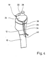
- FIG. 1 shows an upper end section of a femur 10 which is prepared for the implantation of a hip joint prosthesis part.
- the joint ball and the neck of the joint have been completely removed, and the compact solid outer layer (compact) is sawn out on the front side of the bone, so that a window 12 is obtained.
- the cancellous bone from the femur 10 is largely cleared up to the compact, so that a cavity 14 is created. Remnants of the cancellous bone are still visible at 16 in FIG. The sponge-like mesh spaces can be seen there.
- a prosthesis part designated in total by 18, is inserted.
- the latter includes a support wall 20, which essentially has the shape of a double angle, one angled snake 22 running to the minor trochanter, while the second angled leg 24 creates a flush connection to the Adam's arch.
- the support wall 20 thus represents a cap which closes the upper end of the cavity 14 flush.
- a pin 26 is formed on the support wall 20, to which a joint ball 28 can be mechanically fastened, which is indicated by dashed lines in FIG. 1.
- This joint ball works together with a joint socket to be implanted in the pelvis, which is not shown in the drawing.
- the axis of the pin 26 is adjusted in such a way that a valgus position overall, that is to say a position of the joint point which is adjacent to the axis of the bone shaft, and the desired anti-torsion angle are obtained for the joint ball 28.
- a multiplicity of integrally formed anchoring posts 30 extend inwards into the cavity 14.
- the basic direction of extension of the anchoring pillars 30 is essentially parallel to the axis of the pin 26 and thus lies in the main direction of loading (direction of the trabecular traiectors).
- the individual anchoring pillars 30 are somewhat curved, a part of these anchoring pillars being slightly more curved in a section adjacent to the pillar foot, so that these anchoring pillars can be fixed on the second angle leg 24.
- the free ends of the anchoring pillars 30 end at a distance in front of the wall of the cavity 14, which is made of compact in FIG. 1 on the right.
- the anchoring pillars 30 each have a plurality of axially successive anchoring collars 32 which have a rounded edge.
- the anchoring pillars 30 are distributed at substantially the same distance from one another via the cavity 14, so that elongated or columnar free spaces which have essentially the same cross section remain between them.
- the annular end faces of the anchoring collars 32, the thickness of the anchoring collars 32, the axial spacing of the anchoring collars 32, the thickness of the core sections of the anchoring pillars 30, and the length, number and spacing of the anchoring pillars 30 are overall dimensioned such that the local loads are reduced Healing of the prosthetic part on the anchoring pillars of grown cancellous bone is not so large that permanent damage to the cancellous bone occurs, but conversely it is not so small that the mechani desired for the constant renewal of the cancellous bone There are no stimuli and minor destruction on individual meshes.
- short-term loads should occasionally occur in the cancellous bone, which are approximately 120% to 140% of the pressure flow limit of the respective cancellous bone type.
- the load can be around 60% to 80% of the pressure yield limit.
- the cancellous bone contained in the femur with a pressure flow limit of 2.0 N / mm2 this means that 32 surface pressures of a maximum of 2.8 N / mm2 should occur on the anchoring bundles.
- the ring area and number of anchoring collars 32 should be selected accordingly.
- the total surface of the anchoring pillars should be approximately 130% to approximately 270% of the wall surface of the cavity 14, from which the cancellous bone for implanting the prosthetic part is removed.
- the prosthesis part 18 is a one-piece casting which is made of a tissue compatible metal, e.g. CoCrMo biomaterial is produced.
- FIG. 2 shows a second phase of the prosthesis implantation, in which the spaces between the anchoring pillars 30 are filled with ground cancellous material, which was previously removed from the bone to form the cavity 14.
- ground cancellous material which was previously removed from the bone to form the cavity 14.
- FIG. 2 shows a second phase of the prosthesis implantation, in which the spaces between the anchoring pillars 30 are filled with ground cancellous material, which was previously removed from the bone to form the cavity 14.
- FIG. 2 shows a second phase of the prosthesis implantation, in which the spaces between the anchoring pillars 30 are filled with ground cancellous material, which was previously removed from the bone to form the cavity 14.
- FIG. 2 shows a second phase of the prosthesis implantation, in
- FIG. 3 shows the thigh bone after filling the spaces between the anchoring pillars 30 Cancellous particles and after closing the window 12 by the previously sawed-out compact piece 36.
- the compact piece 36 is fixed in its position by two wires 38, 40 made of biomaterial.
- Another wire 42 which is positioned in the groove between the first angle leg 22 and the pin 26, serves to temporarily fix the prosthesis part 18 to the femur until the cancellous material filled between the anchoring pillars 30 grows together and grows against the outer surfaces of the anchoring pillars 30 is.
- This growth of the prosthesis part 18 has progressed to such an extent after about 8 weeks that the prosthesis part 18 is firmly seated. After a year, the anchoring pillars 30 have grown solidly.
- the anchoring collars 32 When the prosthesis part has solidly grown in, the anchoring collars 32 have grown into the cancellous bone, so that no relative movement between the anchoring pillars 30 and the cancellous bone is possible in the longitudinal direction of the pillar. Since there is a large contact area between the cancellous bone and the anchoring pillars, even large static loads can be safely transferred from the prosthesis part 18 to the bone, this transfer taking place via the porous structure having cancellous bone, so that shock loads are damped.
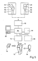
- the prosthesis part 18 is specially manufactured for the special application.
- two X-ray images 44, 48 are assumed, which show the upper end of the femur to be provided with the prosthesis part 18 viewed from the front or viewed from the inside of the pelvis.
- These two to each other Vertical pictures of the upper end of the thigh bone already give quite good information about the spatial geometrical relationships.
- the edge contour of the bone is specified by a line 50 and 52, respectively.
- the surgeon has designated the line on which he wants to sever the joint head by dashed lines 54, 56.
- Lines 58, 60 marked by crosses mark the volume in the upper bone end section in which the surgeon intends to clear out the cancellous bone in order to create the cavity 14. Overall, this space is available for the anchoring piers.
- Lines 50-60 are entered via a digitizing device 62 into a programmable computer 64 which works together with a display device 66 and a hard disk memory 68.
- the computer 64 is connected to a numerically controlled machine tool 70, which mills a 1: 1 model of the upper end of the femur from a block of material, in which the cavity 14 is provided to scale.
- This model is shown in perspective at 72.
- the bone model 72 is derived exclusively from the information which can be gathered from the lines 50-60; Cross sections through the bone model 72 perpendicular to the axis of the bone shaft are thus essentially rectangular. Where such a model is too coarse for practical use, it can be refined in the manner described in more detail below.
- the machine tool 70 under the control of the computer 64, also produces a model 76 of the supporting wall 20 of the prosthesis part 18, which closes the upper end of the bone model 72 flush represents the cover, and a side cover 78, which closes the cavity 14 and represents a model of the compact piece 36.
- a 1: 1 model of the prosthesis part 18 can then be produced by equipping the supporting wall model 76 with 1: 1 models of the anchoring posts 30, which e.g. starting from the continuous material 80 reproduced on an enlarged scale in FIG.
- This pillar model material can be produced in a continuous process; individual model rings for the anchoring collars 32 can also be pushed onto a corresponding core material in a press fit or glued there.
- the computer 64 is also connected to a plotter 82 which, taking into account the cross section of the individual anchoring pillars 30, taking into account the inclination of the pin 26 and taking into account the desired distance between the anchoring pillars 30, generates an occupancy plan for the anchoring pillar models.
- This can e.g. in the form of two side views of the model, which correspond to the viewing directions of the two X-ray images 44 and 48.
- the computer 64 can control the machine tool 70 such that blind holes are drilled into the supporting wall model 76 at the base points of the pillar models, the inclination of which corresponds to the slope of the anchoring pillars 30 at the base point.
- FIG. 7 shows a supporting wall model 76, on which a peg model 84 is attached and which already carries two pillar models 86, 88. Further pillar models must still be attached according to the occupancy plan output by the computer via the plotter 82.
- the pillar models 86, 88 cut to length from the endless pillar model material 80 in such a way that the model bundles corresponding to the anchoring bundles 32 are offset from one another by half a division. This largely prevents circumferentially closed notch arrangements around the cancellous bone columns, which later grow between the anchoring pillars 30.
- the pillar model 88 is bent at its lower end towards the pillar model 86 and connected to the latter, so that a transverse reinforcement in the pillar assembly is also obtained.
- FIG. 8 shows a transverse section through the pillar model arrangement, from which it can be seen that the different pillar models are evenly distributed, so that between them there remain essentially the same cross-sectional area 90, which can be filled with cancellous material.
- the section plane of Figure 8 is chosen to pass through one set of collars (that of pillar models 88) while the collars of the other set of pillar models are outside the plane of the drawing.
- the model of the prosthesis part 18 formed by the supporting wall model 76, the peg model 84 and the various pillar models 86, 88 is made overall of a material which becomes liquid or which evaporates or decomposes when exposed to moderate heat.
- a negative casting mold can then be produced by producing a sand mold and, after it has hardened, the model material is removed by a heat treatment.
- the liquid biomaterial is then poured into the casting mold and, after it has solidified, the casting is removed from the casting mold and cleaned, the molding sand remaining between the anchoring pillars is removed thoroughly, e.g. by sandblasting.
- the blank is then mechanically processed as necessary. eg deburred. This can then be followed by an additional surface treatment, for example polishing and surface coating with titanium.
- the three-dimensional geometric data of various characteristic types of thigh bones are stored on the hard disk memory 68, for example in the form of the edge contours in the longitudinal direction of the shaft of successive cuts, that is to say transverse cuts through the bone.
- the computer checks for the different types of bone deposited, which type can best be brought into line with the digitized edge contours of the x-ray images 44, 48 by means of a similarity transformation (linear expansion or compression). This can be done, for example, by considering the mean square deviation between the edge contour lines 50, 52 obtained by digitization and the corresponding lines of the bone types stored in the fixed location memory 68.
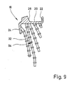
- FIG. 9 shows a section through the central plane of the prosthesis part 18, but for the sake of clarity only the first of the anchoring pillars lying behind the plane of the drawing are shown.
- An opening 92 can be seen in the angled leg 22, through which opening the tension band is serving wire 42 can be pulled, which in turn is fixed in a through hole in the femur 10.
- the anchoring pillars 32 can have the following dimensions, for example, if the prosthesis part is cast from CoCrMo biomaterial: - Core diameter of the anchoring pillars 2 mm - Diameter of the anchoring collars 4 mm - axial distance of the anchoring collars 6 mm - Distance of the anchoring pillars in the area in which they run approximately parallel to each other 8 mm - Length of the anchoring collars according to the space available in cavity 14 (longest anchoring posts still protrude into the uppermost part of the bone shaft) - Inclination of the anchoring collars at a distance from the base approximately according to the inclination of the axis of the pin 26 (longest anchoring pillar curved in the lowest section towards the axis of the bone shaft (continuation of the longest anchoring pillar shown in FIG. 1) - Thickness of the anchoring collars 1 mm
- the angled support wall 20 carries four large core diameter primary anchoring posts 102, 104, 106 and 108, the free ends of which have a prosthesis end piece 110 is cast together, which has essentially the shape of an olive and is smooth on the outside.
- the primary anchoring pillars 102-108 thus form an Eifel tower-like frame construction, the individual anchoring pillars together forming a highly resilient cage, the transverse cross section of which decreases from the supporting wall 20 to the end piece 110.
- the individual anchoring pillars are curved so that they can meet the cancellous volume that can be cleared out in the end of the femur up to the edge.
- the anchoring pillar 106 has a curved pillar section 112 in order to be able to adapt particularly well to the cancellous space.
- the primary anchoring posts 102-108 which extend essentially in the longitudinal direction of the prosthesis, are connected by anchoring posts 114, 116, 118 and 120, which run essentially in the circumferential direction and which lie at different heights.
- the anchoring pillars 102-108 and 114-120 each have a core diameter of 3.5 mm, while anchoring collars 122 arranged on them have an outside diameter of 4.8 mm and follow one another at a distance of 3 mm.
- the axial dimension of the anchoring collars is approximately 0.6 mm in each case.
- the length of the secondary anchoring posts 124 is approximately 15-25 mm, with the secondary anchoring posts 124 also being aligned along trabecular trajectories, and some of these secondary anchoring posts 124 may have curved portions, as shown at 126, therewith they better fit the contour of the cancellous bone volume, and the ends of some of the secondary anchoring posts 124 may also be potted with those of other secondary anchoring posts or with a primary anchoring post, as shown at 128.
- such secondary anchoring pillars can also be used by the primary anchoring pillars 102-108 or by Provide the strong anchoring pillars 114-120 running in the circumferential direction.
- the prosthesis part shown in FIG. 10 thus consists of a cage which specifies the outer contour and is shaped to match the cancellous bone volume of the bone end, the interior of which is essentially uniformly filled with secondary anchoring posts 124. In this way, a very large contact area is obtained between the prosthetic part and the regenerated cancellous bone that has grown firmly between the primary and secondary anchoring posts after implantation. Accordingly, a very uniform and gentle application of force to the end of the bone is obtained. Since, as in the exemplary embodiments described above, no cement or adhesive is required, the anchoring of the prosthetic part takes place purely biomechanically and is thus constantly renewed and supplemented, a good fit of the prosthetic part is also guaranteed in the long term.
- the secondary anchoring posts have a core diameter of 2.5 mm and an outside diameter of their anchoring collars 130 of 4 mm, the anchoring collars again being at a distance of about 3 mm in the longitudinal direction of the pillar.
- Even weaker sized secondary anchoring posts that can replace part of the secondary anchoring posts 124 have a 2.2 mm core diameter, an outside diameter of the anchoring collars of 3 mm and a spacing of the anchoring collars of 3 mm. The distance between these anchoring pillars is 6 to 8 mm.
- the prosthesis part shown in FIG. 10 can be regarded as a linear sponge, which can hold ground cancellous bone well between the secondary anchoring pillars 124. This makes it possible to fill the ground cancellous bone between the secondary anchoring posts 124 before implanting the prosthetic part and to insert the thus filled prosthetic part into the end of the bone.
- This type of procedure does not make it necessary to stuff larger quantities of ground cancellous bone between the anchoring posts 124 after the prosthetic part has been inserted, and it is therefore not necessary to have a large access opening to the implantation site.
- the prosthesis part shown in FIG. 10 is therefore particularly well suited for insertion from the narrow side of the bone end, and this makes it possible to carry out the implantation without detaching the muscle ends that have grown on the bone. This can speed up the healing process considerably.
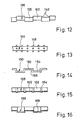
- Figure 11 shows a section of a modified Anchoring pillar 132, which has frusto-conical anchoring collars 134.
- Such an anchoring pillar can be loaded particularly well in the direction in which the forces are directed onto the broad end face of the anchoring collars 134.
- the anchoring pillar 132 in the prosthesis part can be particularly suitable for absorbing compressive loads (wide base surface facing upwards) or for absorbing tensile loads (wide base surface facing downwards).
- Figure 12 shows a section of an anchoring pillar 136 which consists of two nested sets of cylindrical pillar sections 138, 140, the axes of which are parallel and spaced apart. In this way, sickle-shaped shoulders 142 are obtained which assume the function of the annular end faces of the forms of anchoring collars described above.
- the anchor pillar 136 is a one-piece casting or forging.
- anchoring balls 146 are firmly attached to a smooth core, e.g. cast on, which can be overgrown by the bone material.
- FIG. 14 shows an anchoring pillar 150, for example made of titanium, with pillar sections 152 and 154 which run parallel at a transverse distance and are connected by transverse pillar sections 156.
- the anchoring pillar 158 shown in FIG. 15 is a trough-shaped bent sheet metal part with a bottom wall 160 and side walls 162. Beadings 164 running in the transverse direction are embossed, which provide holding possibilities for the bone material both with their outside and with their inside surface.
- the anchoring pillar 160 according to FIG. 16 is also a channel-shaped bent sheet metal part, which, however, now has a semicircular cross section and into which beads 168 are pressed, the width of which corresponds approximately to the bead spacing.
- the outer surface and inner surface offer shoulders against which the renewable bone material can rest.
- anchoring pillars described above have in common that their axis or their main direction of extension in the prosthetic part runs along one of the main directions of tension in the bone and that they provide a large number of radial surfaces which cause an axial relative movement between the anchoring pillar and the grown on it Prevent regenerated bone material and on the one hand gently transfer a small part of the forces to be transferred from the prosthesis to the end of the bone and on the other hand stimulate it to the adjacent cancellous bone volume for natural ongoing regeneration.
Landscapes
- Health & Medical Sciences (AREA)
- Engineering & Computer Science (AREA)
- Orthopedic Medicine & Surgery (AREA)
- Vascular Medicine (AREA)
- Animal Behavior & Ethology (AREA)
- Oral & Maxillofacial Surgery (AREA)
- Biomedical Technology (AREA)
- Heart & Thoracic Surgery (AREA)
- Cardiology (AREA)
- Life Sciences & Earth Sciences (AREA)
- Transplantation (AREA)
- General Health & Medical Sciences (AREA)
- Public Health (AREA)
- Veterinary Medicine (AREA)
- Physics & Mathematics (AREA)
- Geometry (AREA)
- Manufacturing & Machinery (AREA)
- Prostheses (AREA)
Applications Claiming Priority (4)
| Application Number | Priority Date | Filing Date | Title |
|---|---|---|---|
| DE3616665 | 1986-05-16 | ||
| DE3616665 | 1986-05-16 | ||
| DE3707518 | 1987-03-09 | ||
| DE19873707518 DE3707518A1 (de) | 1986-05-16 | 1987-03-09 | Prothesenteil sowie verfahren zu seiner herstellung |
Publications (3)
| Publication Number | Publication Date |
|---|---|
| EP0245846A2 true EP0245846A2 (fr) | 1987-11-19 |
| EP0245846A3 EP0245846A3 (en) | 1988-11-02 |
| EP0245846B1 EP0245846B1 (fr) | 1991-01-02 |
Family
ID=25843851
Family Applications (1)
| Application Number | Title | Priority Date | Filing Date |
|---|---|---|---|
| EP87106896A Expired - Lifetime EP0245846B1 (fr) | 1986-05-16 | 1987-05-12 | Dispositif prothétique et son procédé de fabrication |
Country Status (3)
| Country | Link |
|---|---|
| US (1) | US5002579A (fr) |
| EP (1) | EP0245846B1 (fr) |
| DE (2) | DE3707518A1 (fr) |
Cited By (7)
| Publication number | Priority date | Publication date | Assignee | Title |
|---|---|---|---|---|
| EP0311749A1 (fr) * | 1987-09-17 | 1989-04-19 | Howmedica GmbH | Partie fémorale d'une endoprothèse pour l'articulation de la hanche |
| DE3902775A1 (de) * | 1989-01-31 | 1990-08-02 | Labitzke Reiner Prof Dr Med Ha | Oberschenkelgelenk-prothese |
| EP0442256A2 (fr) * | 1990-02-14 | 1991-08-21 | MAN Ceramics GmbH | Implant osseux |
| FR2690841A1 (fr) * | 1992-05-08 | 1993-11-12 | Ahnfeldt Hartwig | Prothèse d'articulation de la hanche. |
| US5376126A (en) * | 1993-11-12 | 1994-12-27 | Lin; Chih-I | Artificial acetabular joint replacing device |
| WO1995007060A1 (fr) * | 1993-09-07 | 1995-03-16 | Franz Copf | Prothese pour petites articulations |
| EP0826343A2 (fr) * | 1994-08-15 | 1998-03-04 | Shedrick D. Jones | Méthode et appareil pour l'encastrement d'un implant en tissu osseux |
Families Citing this family (108)
| Publication number | Priority date | Publication date | Assignee | Title |
|---|---|---|---|---|
| DE3728686A1 (de) * | 1987-08-27 | 1989-03-09 | Draenert Klaus | Vorspannbares chirurgisches netzwerk |
| DE3822854A1 (de) * | 1988-07-06 | 1990-01-11 | Roland Man Druckmasch | Gelenkprothese fuer ein hueftgelenk |
| EP0647436A1 (fr) * | 1993-10-06 | 1995-04-12 | SMITH & NEPHEW RICHARDS, INC. | Dispositif pour ré-attacher une partie d'os |
| SE501733C2 (sv) * | 1993-12-09 | 1995-05-02 | Nobelpharma Ab | Anordning för att befrämja bentillväxt |
| US6105235A (en) * | 1994-04-28 | 2000-08-22 | Johnson & Johnson Professional, Inc. | Ceramic/metallic articulation component and prosthesis |
| US6494918B1 (en) | 2000-01-30 | 2002-12-17 | Diamicron, Inc. | Component for a prosthetic joint having a diamond load bearing and articulation surface |
| US6596225B1 (en) | 2000-01-31 | 2003-07-22 | Diamicron, Inc. | Methods for manufacturing a diamond prosthetic joint component |
| US6290726B1 (en) | 2000-01-30 | 2001-09-18 | Diamicron, Inc. | Prosthetic hip joint having sintered polycrystalline diamond compact articulation surfaces |
| US7494507B2 (en) * | 2000-01-30 | 2009-02-24 | Diamicron, Inc. | Articulating diamond-surfaced spinal implants |
| US7396505B2 (en) * | 1994-08-12 | 2008-07-08 | Diamicron, Inc. | Use of CoCrMo to augment biocompatibility in polycrystalline diamond compacts |
| US6425922B1 (en) | 2000-01-30 | 2002-07-30 | Diamicron, Inc. | Prosthetic hip joint having at least one sintered polycrystalline diamond compact articulation surface |
| US7077867B1 (en) | 1994-08-12 | 2006-07-18 | Diamicron, Inc. | Prosthetic knee joint having at least one diamond articulation surface |
| US6800095B1 (en) | 1994-08-12 | 2004-10-05 | Diamicron, Inc. | Diamond-surfaced femoral head for use in a prosthetic joint |
| US6497727B1 (en) | 2000-01-30 | 2002-12-24 | Diamicron, Inc. | Component for use in prosthetic hip, the component having a polycrystalline diamond articulation surface and a plurality of substrate layers |
| US6402787B1 (en) | 2000-01-30 | 2002-06-11 | Bill J. Pope | Prosthetic hip joint having at least one sintered polycrystalline diamond compact articulation surface and substrate surface topographical features in said polycrystalline diamond compact |
| CH689725A5 (de) * | 1994-09-08 | 1999-09-30 | Franz Dr Sutter | Gelenkkopf-Prothese. |
| DE19610729A1 (de) * | 1996-03-19 | 1997-09-25 | Franz Prof Dr Med Copf | Prothesenteil |
| DE19613078A1 (de) * | 1996-04-02 | 1997-10-09 | Franz Prof Dr Med Copf | Prothesenteil |
| DE19635307A1 (de) | 1996-09-01 | 1998-03-05 | Copf Franz Prof Dr Med | Prothesenteil |
| US7255712B1 (en) * | 1997-04-15 | 2007-08-14 | Active Implants Corporation | Bone growth promoting implant |
| DE19740689A1 (de) | 1997-09-16 | 1999-03-18 | Franz Prof Dr Med Copf | Oberschenkelprothese |
| US6228123B1 (en) | 1998-08-19 | 2001-05-08 | Depuy Orthopaedics, Inc. | Variable modulus prosthetic hip stem |
| US6410877B1 (en) | 2000-01-30 | 2002-06-25 | Diamicron, Inc. | Methods for shaping and finishing prosthetic joint components including polycrystalline diamond compacts |
| US6709463B1 (en) | 2000-01-30 | 2004-03-23 | Diamicron, Inc. | Prosthetic joint component having at least one solid polycrystalline diamond component |
| EP1455692B1 (fr) | 2001-12-04 | 2010-02-17 | Active Implants Corporation | Implants portant des coussinets pour applications portant une charge |
| DE20120241U1 (de) | 2001-12-14 | 2003-04-24 | Keramed Medizintechnik Gmbh | Gelenk-Endoprothese |
| EP1509161B1 (fr) * | 2002-05-23 | 2009-05-13 | Active Implants Corporation | Implants articulaires et dentaires |
| US7534271B2 (en) * | 2004-01-22 | 2009-05-19 | Smith + Nephew | Femoral hip prosthesis and method of implantation |
| US8353965B2 (en) * | 2004-09-03 | 2013-01-15 | Seitz Jr William H | Small joint orthopedic implants and their manufacture |
| US8377066B2 (en) | 2006-02-27 | 2013-02-19 | Biomet Manufacturing Corp. | Patient-specific elbow guides and associated methods |
| US8282646B2 (en) | 2006-02-27 | 2012-10-09 | Biomet Manufacturing Corp. | Patient specific knee alignment guide and associated method |
| US8568487B2 (en) | 2006-02-27 | 2013-10-29 | Biomet Manufacturing, Llc | Patient-specific hip joint devices |
| US8473305B2 (en) | 2007-04-17 | 2013-06-25 | Biomet Manufacturing Corp. | Method and apparatus for manufacturing an implant |
| US8858561B2 (en) | 2006-06-09 | 2014-10-14 | Blomet Manufacturing, LLC | Patient-specific alignment guide |
| US8298237B2 (en) * | 2006-06-09 | 2012-10-30 | Biomet Manufacturing Corp. | Patient-specific alignment guide for multiple incisions |
| US8070752B2 (en) | 2006-02-27 | 2011-12-06 | Biomet Manufacturing Corp. | Patient specific alignment guide and inter-operative adjustment |
| US9345548B2 (en) | 2006-02-27 | 2016-05-24 | Biomet Manufacturing, Llc | Patient-specific pre-operative planning |
| US8603180B2 (en) | 2006-02-27 | 2013-12-10 | Biomet Manufacturing, Llc | Patient-specific acetabular alignment guides |
| US20150335438A1 (en) | 2006-02-27 | 2015-11-26 | Biomet Manufacturing, Llc. | Patient-specific augments |
| US9173661B2 (en) | 2006-02-27 | 2015-11-03 | Biomet Manufacturing, Llc | Patient specific alignment guide with cutting surface and laser indicator |
| US9339278B2 (en) | 2006-02-27 | 2016-05-17 | Biomet Manufacturing, Llc | Patient-specific acetabular guides and associated instruments |
| US8864769B2 (en) | 2006-02-27 | 2014-10-21 | Biomet Manufacturing, Llc | Alignment guides with patient-specific anchoring elements |
| US8608748B2 (en) * | 2006-02-27 | 2013-12-17 | Biomet Manufacturing, Llc | Patient specific guides |
| US8241293B2 (en) * | 2006-02-27 | 2012-08-14 | Biomet Manufacturing Corp. | Patient specific high tibia osteotomy |
| US8591516B2 (en) | 2006-02-27 | 2013-11-26 | Biomet Manufacturing, Llc | Patient-specific orthopedic instruments |
| US10278711B2 (en) | 2006-02-27 | 2019-05-07 | Biomet Manufacturing, Llc | Patient-specific femoral guide |
| US9918740B2 (en) | 2006-02-27 | 2018-03-20 | Biomet Manufacturing, Llc | Backup surgical instrument system and method |
| US8092465B2 (en) | 2006-06-09 | 2012-01-10 | Biomet Manufacturing Corp. | Patient specific knee alignment guide and associated method |
| US8407067B2 (en) | 2007-04-17 | 2013-03-26 | Biomet Manufacturing Corp. | Method and apparatus for manufacturing an implant |
| US8608749B2 (en) | 2006-02-27 | 2013-12-17 | Biomet Manufacturing, Llc | Patient-specific acetabular guides and associated instruments |
| US9113971B2 (en) | 2006-02-27 | 2015-08-25 | Biomet Manufacturing, Llc | Femoral acetabular impingement guide |
| US8535387B2 (en) | 2006-02-27 | 2013-09-17 | Biomet Manufacturing, Llc | Patient-specific tools and implants |
| US9907659B2 (en) * | 2007-04-17 | 2018-03-06 | Biomet Manufacturing, Llc | Method and apparatus for manufacturing an implant |
| US7967868B2 (en) | 2007-04-17 | 2011-06-28 | Biomet Manufacturing Corp. | Patient-modified implant and associated method |
| US9289253B2 (en) | 2006-02-27 | 2016-03-22 | Biomet Manufacturing, Llc | Patient-specific shoulder guide |
| US8133234B2 (en) * | 2006-02-27 | 2012-03-13 | Biomet Manufacturing Corp. | Patient specific acetabular guide and method |
| US9795399B2 (en) | 2006-06-09 | 2017-10-24 | Biomet Manufacturing, Llc | Patient-specific knee alignment guide and associated method |
| US8265949B2 (en) * | 2007-09-27 | 2012-09-11 | Depuy Products, Inc. | Customized patient surgical plan |
| US8357111B2 (en) * | 2007-09-30 | 2013-01-22 | Depuy Products, Inc. | Method and system for designing patient-specific orthopaedic surgical instruments |
| EP2957237A1 (fr) * | 2007-09-30 | 2015-12-23 | DePuy Products, Inc. | Instrument chirurgical orthopédique personnalisé spécifique d'un patient |
| DE102008014466A1 (de) * | 2008-03-17 | 2009-09-24 | Franz Prof. Dr. med. Copf sen. | Prothesenkörper für eine Oberschenkel-Prothese |
| US20100185202A1 (en) * | 2009-01-16 | 2010-07-22 | Lester Mark B | Customized patient-specific patella resectioning guide |
| US8170641B2 (en) | 2009-02-20 | 2012-05-01 | Biomet Manufacturing Corp. | Method of imaging an extremity of a patient |
| DE102009028503B4 (de) | 2009-08-13 | 2013-11-14 | Biomet Manufacturing Corp. | Resektionsschablone zur Resektion von Knochen, Verfahren zur Herstellung einer solchen Resektionsschablone und Operationsset zur Durchführung von Kniegelenk-Operationen |
| US8470049B2 (en) * | 2009-09-01 | 2013-06-25 | Concept, Design And Development, Llc | Neck sparing total hip implant system |
| US8632547B2 (en) | 2010-02-26 | 2014-01-21 | Biomet Sports Medicine, Llc | Patient-specific osteotomy devices and methods |
| US9066727B2 (en) | 2010-03-04 | 2015-06-30 | Materialise Nv | Patient-specific computed tomography guides |
| US9271744B2 (en) | 2010-09-29 | 2016-03-01 | Biomet Manufacturing, Llc | Patient-specific guide for partial acetabular socket replacement |
| US9968376B2 (en) | 2010-11-29 | 2018-05-15 | Biomet Manufacturing, Llc | Patient-specific orthopedic instruments |
| US9241745B2 (en) | 2011-03-07 | 2016-01-26 | Biomet Manufacturing, Llc | Patient-specific femoral version guide |
| US8715289B2 (en) | 2011-04-15 | 2014-05-06 | Biomet Manufacturing, Llc | Patient-specific numerically controlled instrument |
| US9675400B2 (en) | 2011-04-19 | 2017-06-13 | Biomet Manufacturing, Llc | Patient-specific fracture fixation instrumentation and method |
| US8956364B2 (en) | 2011-04-29 | 2015-02-17 | Biomet Manufacturing, Llc | Patient-specific partial knee guides and other instruments |
| US8668700B2 (en) | 2011-04-29 | 2014-03-11 | Biomet Manufacturing, Llc | Patient-specific convertible guides |
| US8532807B2 (en) | 2011-06-06 | 2013-09-10 | Biomet Manufacturing, Llc | Pre-operative planning and manufacturing method for orthopedic procedure |
| US9084618B2 (en) | 2011-06-13 | 2015-07-21 | Biomet Manufacturing, Llc | Drill guides for confirming alignment of patient-specific alignment guides |
| WO2012173605A1 (fr) * | 2011-06-14 | 2012-12-20 | Concept, Design And Development, Llc | Système d'implant de hanche total épargnant le col du fémur |
| US8764760B2 (en) | 2011-07-01 | 2014-07-01 | Biomet Manufacturing, Llc | Patient-specific bone-cutting guidance instruments and methods |
| US20130001121A1 (en) | 2011-07-01 | 2013-01-03 | Biomet Manufacturing Corp. | Backup kit for a patient-specific arthroplasty kit assembly |
| US8597365B2 (en) | 2011-08-04 | 2013-12-03 | Biomet Manufacturing, Llc | Patient-specific pelvic implants for acetabular reconstruction |
| US9295497B2 (en) | 2011-08-31 | 2016-03-29 | Biomet Manufacturing, Llc | Patient-specific sacroiliac and pedicle guides |
| US9066734B2 (en) | 2011-08-31 | 2015-06-30 | Biomet Manufacturing, Llc | Patient-specific sacroiliac guides and associated methods |
| US9386993B2 (en) | 2011-09-29 | 2016-07-12 | Biomet Manufacturing, Llc | Patient-specific femoroacetabular impingement instruments and methods |
| WO2013062848A1 (fr) | 2011-10-27 | 2013-05-02 | Biomet Manufacturing Corporation | Guides glénoïdes spécifiques d'un patient |
| US9301812B2 (en) | 2011-10-27 | 2016-04-05 | Biomet Manufacturing, Llc | Methods for patient-specific shoulder arthroplasty |
| KR20130046336A (ko) | 2011-10-27 | 2013-05-07 | 삼성전자주식회사 | 디스플레이장치의 멀티뷰 디바이스 및 그 제어방법과, 디스플레이 시스템 |
| US9554910B2 (en) | 2011-10-27 | 2017-01-31 | Biomet Manufacturing, Llc | Patient-specific glenoid guide and implants |
| US9451973B2 (en) | 2011-10-27 | 2016-09-27 | Biomet Manufacturing, Llc | Patient specific glenoid guide |
| US9237950B2 (en) | 2012-02-02 | 2016-01-19 | Biomet Manufacturing, Llc | Implant with patient-specific porous structure |
| US9204977B2 (en) | 2012-12-11 | 2015-12-08 | Biomet Manufacturing, Llc | Patient-specific acetabular guide for anterior approach |
| US9060788B2 (en) | 2012-12-11 | 2015-06-23 | Biomet Manufacturing, Llc | Patient-specific acetabular guide for anterior approach |
| US9839438B2 (en) | 2013-03-11 | 2017-12-12 | Biomet Manufacturing, Llc | Patient-specific glenoid guide with a reusable guide holder |
| US9579107B2 (en) | 2013-03-12 | 2017-02-28 | Biomet Manufacturing, Llc | Multi-point fit for patient specific guide |
| US9826981B2 (en) | 2013-03-13 | 2017-11-28 | Biomet Manufacturing, Llc | Tangential fit of patient-specific guides |
| US9498233B2 (en) | 2013-03-13 | 2016-11-22 | Biomet Manufacturing, Llc. | Universal acetabular guide and associated hardware |
| US9517145B2 (en) | 2013-03-15 | 2016-12-13 | Biomet Manufacturing, Llc | Guide alignment system and method |
| US20150112349A1 (en) | 2013-10-21 | 2015-04-23 | Biomet Manufacturing, Llc | Ligament Guide Registration |
| US10282488B2 (en) | 2014-04-25 | 2019-05-07 | Biomet Manufacturing, Llc | HTO guide with optional guided ACL/PCL tunnels |
| US9408616B2 (en) | 2014-05-12 | 2016-08-09 | Biomet Manufacturing, Llc | Humeral cut guide |
| US9561040B2 (en) | 2014-06-03 | 2017-02-07 | Biomet Manufacturing, Llc | Patient-specific glenoid depth control |
| US9839436B2 (en) | 2014-06-03 | 2017-12-12 | Biomet Manufacturing, Llc | Patient-specific glenoid depth control |
| US9833245B2 (en) | 2014-09-29 | 2017-12-05 | Biomet Sports Medicine, Llc | Tibial tubercule osteotomy |
| US9826994B2 (en) | 2014-09-29 | 2017-11-28 | Biomet Manufacturing, Llc | Adjustable glenoid pin insertion guide |
| US9820868B2 (en) | 2015-03-30 | 2017-11-21 | Biomet Manufacturing, Llc | Method and apparatus for a pin apparatus |
| US10226262B2 (en) | 2015-06-25 | 2019-03-12 | Biomet Manufacturing, Llc | Patient-specific humeral guide designs |
| US10568647B2 (en) | 2015-06-25 | 2020-02-25 | Biomet Manufacturing, Llc | Patient-specific humeral guide designs |
| US10722310B2 (en) | 2017-03-13 | 2020-07-28 | Zimmer Biomet CMF and Thoracic, LLC | Virtual surgery planning system and method |
| US11051829B2 (en) | 2018-06-26 | 2021-07-06 | DePuy Synthes Products, Inc. | Customized patient-specific orthopaedic surgical instrument |
Citations (3)
| Publication number | Priority date | Publication date | Assignee | Title |
|---|---|---|---|---|
| EP0169976A1 (fr) * | 1984-07-03 | 1986-02-05 | GebràDer Sulzer Aktiengesellschaft | Tige d'une prothèse de l'articulation de la hanche présentant à partir de la partie distale un élargissement conique |
| DE3536895A1 (de) * | 1984-11-09 | 1986-05-15 | České vysoké učení technické v Praze, Prag/Praha | Hueftgelenk-endoprothese |
| DE3536894A1 (de) * | 1984-11-09 | 1986-05-15 | České vysoké učení technické v Praze, Prag/Praha | Hueftgelenk-endoprothese |
Family Cites Families (1)
| Publication number | Priority date | Publication date | Assignee | Title |
|---|---|---|---|---|
| US4530114A (en) * | 1982-07-16 | 1985-07-23 | Slobodan Tepic | Total hip joint prostheses |
-
1987
- 1987-03-09 DE DE19873707518 patent/DE3707518A1/de not_active Withdrawn
- 1987-05-12 DE DE8787106896T patent/DE3766878D1/de not_active Expired - Lifetime
- 1987-05-12 EP EP87106896A patent/EP0245846B1/fr not_active Expired - Lifetime
- 1987-05-15 US US07/049,989 patent/US5002579A/en not_active Expired - Fee Related
Patent Citations (3)
| Publication number | Priority date | Publication date | Assignee | Title |
|---|---|---|---|---|
| EP0169976A1 (fr) * | 1984-07-03 | 1986-02-05 | GebràDer Sulzer Aktiengesellschaft | Tige d'une prothèse de l'articulation de la hanche présentant à partir de la partie distale un élargissement conique |
| DE3536895A1 (de) * | 1984-11-09 | 1986-05-15 | České vysoké učení technické v Praze, Prag/Praha | Hueftgelenk-endoprothese |
| DE3536894A1 (de) * | 1984-11-09 | 1986-05-15 | České vysoké učení technické v Praze, Prag/Praha | Hueftgelenk-endoprothese |
Cited By (11)
| Publication number | Priority date | Publication date | Assignee | Title |
|---|---|---|---|---|
| EP0311749A1 (fr) * | 1987-09-17 | 1989-04-19 | Howmedica GmbH | Partie fémorale d'une endoprothèse pour l'articulation de la hanche |
| US4938771A (en) * | 1987-09-17 | 1990-07-03 | Vilmos Vecsei | Femoral portion of a hip joint prosthesis |
| DE3902775A1 (de) * | 1989-01-31 | 1990-08-02 | Labitzke Reiner Prof Dr Med Ha | Oberschenkelgelenk-prothese |
| EP0442256A2 (fr) * | 1990-02-14 | 1991-08-21 | MAN Ceramics GmbH | Implant osseux |
| EP0442256A3 (en) * | 1990-02-14 | 1992-09-30 | Man Technologie Aktiengesellschaft | Bone implant |
| FR2690841A1 (fr) * | 1992-05-08 | 1993-11-12 | Ahnfeldt Hartwig | Prothèse d'articulation de la hanche. |
| WO1995007060A1 (fr) * | 1993-09-07 | 1995-03-16 | Franz Copf | Prothese pour petites articulations |
| US5776202A (en) * | 1993-09-07 | 1998-07-07 | Copf; Franz | Joint prosthesis |
| US5376126A (en) * | 1993-11-12 | 1994-12-27 | Lin; Chih-I | Artificial acetabular joint replacing device |
| EP0826343A2 (fr) * | 1994-08-15 | 1998-03-04 | Shedrick D. Jones | Méthode et appareil pour l'encastrement d'un implant en tissu osseux |
| EP0826343A3 (fr) * | 1994-08-15 | 1998-07-22 | Shedrick D. Jones | Méthode et appareil pour l'encastrement d'un implant en tissu osseux |
Also Published As
| Publication number | Publication date |
|---|---|
| US5002579A (en) | 1991-03-26 |
| DE3707518A1 (de) | 1987-11-26 |
| DE3766878D1 (de) | 1991-02-07 |
| EP0245846B1 (fr) | 1991-01-02 |
| EP0245846A3 (en) | 1988-11-02 |
Similar Documents
| Publication | Publication Date | Title |
|---|---|---|
| EP0245846B1 (fr) | Dispositif prothétique et son procédé de fabrication | |
| DE3106917C2 (de) | Verfahren zur Herstellung eines Implantates als Knochenersatz | |
| DE60022891T2 (de) | Eingeschlagenes orthopädisches knochenstützimplantat | |
| DE69728001T2 (de) | Prothese mit veränderbarer Passungs- und Spannungsverteilung | |
| EP1260200B1 (fr) | Endoprothèse non cimentée de l'articulation de la hanche pour remplacer la surface de la partie proximale du fémur | |
| EP1013236A1 (fr) | Implant dentaire et son procédé de fabrication | |
| DE3639030A1 (de) | Enossales implantat mit polykapillarer struktur | |
| DE2914513B2 (de) | Oberflächenstruktur für Verankerungselemente zur zementfreien Verankerung von Knochenimplantaten | |
| EP0489684A1 (fr) | Implant pour la construction de tissu osseux | |
| EP0502349A1 (fr) | Procédé pour fabriquer un implant avec une structure métallique à pores ouverts recouvrant au moins partiellement sa surface | |
| CH687672A5 (de) | Zur Befestigung eines Zahnersatzes am Kiefer dienendes Implantat. | |
| EP0622056A2 (fr) | Organe d'ancrage implantable pour la réception de prothèses et d'objets similaires | |
| EP0868157B1 (fr) | Implant servant de prothese osseuse | |
| DE4421153A1 (de) | Verfahren zur Herstellung einer Prothese | |
| DE2502884A1 (de) | Mittel zur biologischen implantation von knochen- und gelenkersatz | |
| EP3416594B1 (fr) | Implant pour la reconstruction d'une acétabule et de partie du bassin | |
| DE3416471C2 (de) | Auflage zur Erzeugung einer Oberflächenstruktur für metallene Verankerungselemente von Knochenimplantaten | |
| EP0898469A1 (fr) | Implant et son procede de production | |
| DE3426947A1 (de) | Selbsthaftendes, zementlos implantierbares hueftschaft-implantat | |
| DE19606057C2 (de) | Metallisches Formteil für ein Knochenimplantat | |
| DE2129832A1 (de) | Hueftgelenksprothese und Verfahren zu ihrer Herstellung | |
| EP1336388B1 (fr) | Implant dentaire | |
| EP1326551B1 (fr) | Implant presentant une structure rainuree | |
| DE19915395B4 (de) | Knochenimplantatvorrichtung zur Gewebegenerierung mittels Knochenersatzmaterialien sowie Verfahren zur Herstellung der Knochenimplantatvorrichtung | |
| DE10118985C2 (de) | Hüftgelenkpfannen-System |
Legal Events
| Date | Code | Title | Description |
|---|---|---|---|
| PUAI | Public reference made under article 153(3) epc to a published international application that has entered the european phase |
Free format text: ORIGINAL CODE: 0009012 |
|
| AK | Designated contracting states |
Kind code of ref document: A2 Designated state(s): CH DE FR GB IT LI |
|
| PUAL | Search report despatched |
Free format text: ORIGINAL CODE: 0009013 |
|
| AK | Designated contracting states |
Kind code of ref document: A3 Designated state(s): CH DE FR GB IT LI |
|
| 17P | Request for examination filed |
Effective date: 19881203 |
|
| 17Q | First examination report despatched |
Effective date: 19900111 |
|
| GRAA | (expected) grant |
Free format text: ORIGINAL CODE: 0009210 |
|
| AK | Designated contracting states |
Kind code of ref document: B1 Designated state(s): CH DE FR GB IT LI |
|
| GBT | Gb: translation of ep patent filed (gb section 77(6)(a)/1977) | ||
| REF | Corresponds to: |
Ref document number: 3766878 Country of ref document: DE Date of ref document: 19910207 |
|
| ET | Fr: translation filed | ||
| ITF | It: translation for a ep patent filed |
Owner name: STUDIO JAUMANN |
|
| PLBE | No opposition filed within time limit |
Free format text: ORIGINAL CODE: 0009261 |
|
| STAA | Information on the status of an ep patent application or granted ep patent |
Free format text: STATUS: NO OPPOSITION FILED WITHIN TIME LIMIT |
|
| 26N | No opposition filed | ||
| K2C2 | Correction of patent specification (partial reprint) published |
Effective date: 19910102 |
|
| GBPC | Gb: european patent ceased through non-payment of renewal fee |
Effective date: 19990512 |
|
| REG | Reference to a national code |
Ref country code: GB Ref legal event code: 728V |
|
| REG | Reference to a national code |
Ref country code: GB Ref legal event code: 728Y |
|
| PGFP | Annual fee paid to national office [announced via postgrant information from national office to epo] |
Ref country code: FR Payment date: 20010518 Year of fee payment: 15 |
|
| PGFP | Annual fee paid to national office [announced via postgrant information from national office to epo] |
Ref country code: GB Payment date: 20010525 Year of fee payment: 15 |
|
| PGFP | Annual fee paid to national office [announced via postgrant information from national office to epo] |
Ref country code: CH Payment date: 20010528 Year of fee payment: 15 |
|
| REG | Reference to a national code |
Ref country code: GB Ref legal event code: IF02 |
|
| PG25 | Lapsed in a contracting state [announced via postgrant information from national office to epo] |
Ref country code: GB Free format text: LAPSE BECAUSE OF NON-PAYMENT OF DUE FEES Effective date: 20020512 |
|
| PG25 | Lapsed in a contracting state [announced via postgrant information from national office to epo] |
Ref country code: LI Free format text: LAPSE BECAUSE OF NON-PAYMENT OF DUE FEES Effective date: 20020531 Ref country code: CH Free format text: LAPSE BECAUSE OF NON-PAYMENT OF DUE FEES Effective date: 20020531 |
|
| GBPC | Gb: european patent ceased through non-payment of renewal fee |
Effective date: 20020512 |
|
| REG | Reference to a national code |
Ref country code: CH Ref legal event code: PL |
|
| PG25 | Lapsed in a contracting state [announced via postgrant information from national office to epo] |
Ref country code: FR Free format text: LAPSE BECAUSE OF NON-PAYMENT OF DUE FEES Effective date: 20030131 |
|
| REG | Reference to a national code |
Ref country code: FR Ref legal event code: ST |
|
| PGFP | Annual fee paid to national office [announced via postgrant information from national office to epo] |
Ref country code: DE Payment date: 20040726 Year of fee payment: 18 |
|
| PG25 | Lapsed in a contracting state [announced via postgrant information from national office to epo] |
Ref country code: IT Free format text: LAPSE BECAUSE OF NON-PAYMENT OF DUE FEES Effective date: 20050512 |
|
| PG25 | Lapsed in a contracting state [announced via postgrant information from national office to epo] |
Ref country code: DE Free format text: LAPSE BECAUSE OF NON-PAYMENT OF DUE FEES Effective date: 20051201 |