EP0244883A2 - Procédé de saisissage de données par ligne de transmission utilisant des capteurs optiques - Google Patents
Procédé de saisissage de données par ligne de transmission utilisant des capteurs optiques Download PDFInfo
- Publication number
- EP0244883A2 EP0244883A2 EP87200279A EP87200279A EP0244883A2 EP 0244883 A2 EP0244883 A2 EP 0244883A2 EP 87200279 A EP87200279 A EP 87200279A EP 87200279 A EP87200279 A EP 87200279A EP 0244883 A2 EP0244883 A2 EP 0244883A2
- Authority
- EP
- European Patent Office
- Prior art keywords
- modulation
- frequency
- optical
- low
- receiving device
- Prior art date
- Legal status (The legal status is an assumption and is not a legal conclusion. Google has not performed a legal analysis and makes no representation as to the accuracy of the status listed.)
- Granted
Links
Images

Classifications
-
- G—PHYSICS
- G01—MEASURING; TESTING
- G01D—MEASURING NOT SPECIALLY ADAPTED FOR A SPECIFIC VARIABLE; ARRANGEMENTS FOR MEASURING TWO OR MORE VARIABLES NOT COVERED IN A SINGLE OTHER SUBCLASS; TARIFF METERING APPARATUS; MEASURING OR TESTING NOT OTHERWISE PROVIDED FOR
- G01D5/00—Mechanical means for transferring the output of a sensing member; Means for converting the output of a sensing member to another variable where the form or nature of the sensing member does not constrain the means for converting; Transducers not specially adapted for a specific variable
- G01D5/26—Mechanical means for transferring the output of a sensing member; Means for converting the output of a sensing member to another variable where the form or nature of the sensing member does not constrain the means for converting; Transducers not specially adapted for a specific variable characterised by optical transfer means, i.e. using infrared, visible, or ultraviolet light
- G01D5/268—Mechanical means for transferring the output of a sensing member; Means for converting the output of a sensing member to another variable where the form or nature of the sensing member does not constrain the means for converting; Transducers not specially adapted for a specific variable characterised by optical transfer means, i.e. using infrared, visible, or ultraviolet light using optical fibres
-
- H—ELECTRICITY
- H04—ELECTRIC COMMUNICATION TECHNIQUE
- H04B—TRANSMISSION
- H04B10/00—Transmission systems employing electromagnetic waves other than radio-waves, e.g. infrared, visible or ultraviolet light, or employing corpuscular radiation, e.g. quantum communication
- H04B10/50—Transmitters
- H04B10/501—Structural aspects
- H04B10/502—LED transmitters
Definitions
- the invention relates to a method for determining measurement data over an optical transmission path by means of an optical sensor which contains an optical transducer, the optical damping properties of which can be influenced as a function of the measured value and through which a first partial beam of a high-frequency amplitude-modulated optical transmission beam is guided, while a second partial beam this transmission beam is diverted via a delay element and, together with the first partial beam leaving the optical converter, is fed as a reception beam via the transmission path to a receiving device, by means of which the modulation change caused by the sensor is processed and evaluated as information about the measured variable.
- one of the partial beams of the transmitted beam which is not influenced by the transducer of the sensor, is guided through an optical delay line and combined with the time delay with the partial beam influenced by the transducer, and is guided into an optical fiber which is used for transmission to a receiving device.
- the partial beam sent through the delay line forms a reference beam.
- the relative phase angles of the modulation components of the two partial beams are different.
- the resulting phase angle of the received beam is compared with the original phase angle of the transmitted beam.
- the invention is based on the object of designing the method of the type mentioned at the outset in such a way that transmitter-side measurement value acquisition is possible for any optical transmission links of indefinite length without recalibration of the receiving device.
- the solution is achieved in that the optical transmission beam is additionally amplitude-modulated at low frequency, that an original degree of modulation mo of the transmission beam is fixed as the quotient of the low-frequency to high-frequency modulation amplitudes and the receiving device is entered as information that the received modulation degree m 1 of the reception beam influenced by the sensor measured by the receiving device and the ratio of received and original modulation signal is evaluated as information about the measured value.
- Theoretical considerations show that the ratio of the degrees of modulation of the two partial beams is not only independent of the attenuation of the transmission path, but also of its length.
- the modulation frequencies of the high-frequency and the low-frequency modulations are different in the ratio of at least 10 3.
- the high-frequency modulation signal is multiplied by the low-frequency modulation signal and that the peak values of the modulation signals separated by filters are determined.
- a simple, constant circuitry means that an always constant, original degree of modulation m o can be specified.
- Simple circuit designs also result when the high-frequency modulation only overlaps the positive range of the low-frequency modulation. It is not necessary that the duration of the positive half-wave of the low-frequency rectangular modulation be the same as the duration of the negative half-wave. However, it is advantageous that the superimposed high-frequency modulation consists of symmetrical positive and negative half-waves. In principle, this is guaranteed with rectangular modulations regardless of the curvature of the characteristic curve of an LED.
- a particularly simple possibility for forming a known and constant degree of modulation results from the fact that the transmitter sends groups of optical square-wave pulses with a pulse duty factor 1: 1. and that the transmission time of a group is followed by a pause, the length of which is a multiple of the period of the rectangular pulses.
- a particularly high measurement sensitivity is achieved with the method according to the invention if the length of the delay line is approximately an odd multiple of half a wavelength of the high-frequency modulation.
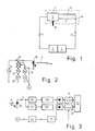
- the known arrangement shown in FIG. 1 consists of sensor 1, transmitter 2 and receiver 3, which are connected to sensor 1 via optical fibers 4 and 5, respectively.
- the optical damping behavior of the transducer 6 is dependent on the measured variable M (eg pressure).
- M eg pressure
- the modulated transmission beam supplied via the FO 4 is divided in the converter into two partial beams, the first of which influenced as much as possible by the measured variable and is conducted into the fiber optic cable 5 via the line 7 and the optical coupler 8.
- the second partial beam (reference beam) which is influenced as little as possible or in the opposite direction to the first partial beam by the measured variable and can also be guided past the converter 6, is passed through the delay line 9 to the coupler 8 and then into the fiber optic cable 5.
- the sum signal is received by the receiver 3, processed and evaluated to form a display representing the measured value M.
- the delay line 9 causes the phases and amplitudes of the modulations of the two partial beams to be different from one another. Any other delay elements could be used instead of a delay line, e.g. luminescent crystals (see Electronics Letters l7, l98l, p. 630).
- the light intensity transmitted by the LED 10 is modulated with high frequency, in particular 100-100 MHz, and low frequency with preferably 0.5 to 2 kHz.
- modulation currents are superimposed on the direct current generated by the direct current source 11 via the superposition element l3.
- the modulation currents are caused by a high-frequency voltage source l4, a low-frequency voltage source l5 and DC voltage sources l6 and l7.
- the voltage sources l4 or l5 can generate sinusoidal or rectangular signals depending on the desired signal profile.
- the optoelectronic converter 18 (photodiode) of the receiver circuit according to FIG. 3 converts the modulated light supplied via the LWL 5 into the same electrical signals in the intensity curve of the light. In addition, however, a dark current I D is superimposed. Through the condens sator C any existing light components of the transmitted signal and the dark current of the optoelectronic converter 18 are blocked.
- the high-pass HP passes the amplified high-frequency modulation signal after peak value rectification into the sample and hold circuit 19 and the low-frequency modulation signal via the low pass TP after amplification and peak value rectification into the sample and hold circuit 20.
- the sample and hold circuits 19 and 20 become clocked with the low-frequency modulation period over the line a coming from the transmitter circuit.
- a delay element 2l enables a desired assignment of the measuring time relative to the maximum of the low-frequency modulation. If the low-frequency modulation is not itself rectangular, 22 rectangular output signals are generated by the threshold switch.
- the evaluation circuit 23 finally decodes the different-frequency modulation signals, so that information proportional to the measured value M can be obtained.
- Circuits which produce rectangular low-frequency modulations in accordance with the signal profiles shown in FIGS. 4 and 5 are particularly simple to implement.
- Transmission times during which high-frequency pulses are transmitted are followed by pauses during which no high-frequency pulses are transmitted.
- Broadcast times and break times can be of different lengths. It is important, however, that the high-frequency modulation frequency HF is much larger than the low-frequency modulation frequency NF or as the low clock frequency of the successive transmission and pause times.
- FIGS. 4, 5 and 6 show signal forms in which the amplitudes of the high-frequency modulations on the transmitter side are twice as large as the amplitudes of the low-frequency modulations.
- the transmission of the offset component I OF as a low-frequency signal gives the advantage that its amplitude can be separated from the constant light components. In particular, dark currents I D of a photodiode of the receiver cannot falsify the value of the offset component.
- FIGS. 4 and 5 each show optical pulse curves on the transmitter side, while on the right-hand side the associated electrical output signals formed by the photodiode 18 are shown.
- the LED l0 whose characteristic 24 has a curved profile, is operated with a control current i 1, which has a time-independent constant component, which causes a constant light I G.
- the LED is operated in an almost linear region of the characteristic curve 24, so that the modulation half-waves are the same.
- Blocks of high-frequency successive pulses are superimposed on the constant component, which cause sinusoidal intensity fluctuations of the transmitted light with the amplitude I HF , which are superimposed on the constant light component I G with an offset intensity I OF .
- the electrical output signal of the photodiode l8 then contains a direct component I ' G , which additionally contains the dark current I D of the photodiode l8.
- a splitting of these current components is not necessary, however, since only the offset component I ' OF is evaluated, which is proportional to the transmitted offset component I OF , unaffected by the dark current I D.
- the value I ' OF is influenced by the measured value M, but not by the delay line 9, while the received signal I' HF additionally due to the effect of the delay line 9 in the relative size Offset portion is reduced.
- the received degree of modulation m 1 has thus changed compared to the transmitted. The extent of this change contains clear information about the measured variable M to be determined.
- the high-frequency modulation in the manner described in FIG. 4 could also take place on the transmitter side with a rectangular profile if a corresponding generator 14 is constructed in a simple manner using toggle switches.
- An evaluation can also be carried out on the receiver side with a circuit according to FIG. 3 if the high-pass filter HP is designed as a band-pass filter, so that only the fundamental harmonic of the rectangular high-frequency transmission modulation is evaluated.
- Transmission T is the ratio of the intensity occurring at the end of a transmission path to the original intensity at the beginning of the transmission path.
- At ⁇ L (2k + l) or if this condition is at least approximated, the greatest measurement sensitivity results.
Landscapes
- Physics & Mathematics (AREA)
- General Physics & Mathematics (AREA)
- Electromagnetism (AREA)
- Engineering & Computer Science (AREA)
- Computer Networks & Wireless Communication (AREA)
- Signal Processing (AREA)
- Optical Communication System (AREA)
- Arrangements For Transmission Of Measured Signals (AREA)
Applications Claiming Priority (2)
| Application Number | Priority Date | Filing Date | Title |
|---|---|---|---|
| DE3606488 | 1986-02-28 | ||
| DE19863606488 DE3606488A1 (de) | 1986-02-28 | 1986-02-28 | Verfahren zur ermittlung von messdaten ueber eine optische uebertragungsstrecke mittels eines optischen sensors |
Publications (3)
| Publication Number | Publication Date |
|---|---|
| EP0244883A2 true EP0244883A2 (fr) | 1987-11-11 |
| EP0244883A3 EP0244883A3 (en) | 1988-12-28 |
| EP0244883B1 EP0244883B1 (fr) | 1991-07-17 |
Family
ID=6295134
Family Applications (1)
| Application Number | Title | Priority Date | Filing Date |
|---|---|---|---|
| EP87200279A Expired - Lifetime EP0244883B1 (fr) | 1986-02-28 | 1987-02-20 | Procédé de saisissage de données par ligne de transmission utilisant des capteurs optiques |
Country Status (4)
| Country | Link |
|---|---|
| US (1) | US4850698A (fr) |
| EP (1) | EP0244883B1 (fr) |
| JP (1) | JPS62204400A (fr) |
| DE (2) | DE3606488A1 (fr) |
Cited By (2)
| Publication number | Priority date | Publication date | Assignee | Title |
|---|---|---|---|---|
| DE3805328A1 (de) * | 1988-02-20 | 1989-08-31 | Asea Brown Boveri | Verfahren zur messwertuebertragung bei einer lichtleiteruebertragung der messwerte |
| DE19548920A1 (de) * | 1994-12-27 | 1996-07-11 | Toshiba Kawasaki Kk | Mit optischer Modulation arbeitender Sensor und diesen Sensor einsetzende Porzeß-Meßgeräteeinrichtung |
Families Citing this family (10)
| Publication number | Priority date | Publication date | Assignee | Title |
|---|---|---|---|---|
| JP2527829B2 (ja) * | 1990-04-25 | 1996-08-28 | 三菱電機株式会社 | 光応用測定装置 |
| FR2664048B1 (fr) * | 1990-06-29 | 1993-08-20 | Centre Nat Rech Scient | Procede et dispositif de detection analogique multicanal. |
| GB9204067D0 (en) * | 1992-02-26 | 1992-04-08 | Sensor Dynamics Ltd | Optical fibre sensor |
| US5535139A (en) * | 1994-04-04 | 1996-07-09 | International Business Machines Corporation | Portable fiber optic splitter tool for multimode optical fiber cable link |
| JP3320996B2 (ja) * | 1996-11-26 | 2002-09-03 | 株式会社東芝 | 波長多重光伝送装置 |
| DE102004004260B3 (de) * | 2004-01-23 | 2005-06-23 | Fraunhofer-Gesellschaft zur Förderung der angewandten Forschung e.V. | Schaltungsanordnung zur Reduzierung von Messfehlern analoger pulsförmiger Messsignale eines Detektors |
| CA2684744C (fr) * | 2007-04-26 | 2016-06-21 | Tyco Healthcare Group Lp | Dispositif d'acces medical multifonctionnel |
| DE102011003306B3 (de) * | 2011-01-28 | 2012-04-05 | Siemens Aktiengesellschaft | Schaltungsanordnung zur Erfassung und Digitalisierung eines analogen Eingangssignals sowie Feldgerät zur Prozessinstrumentierung |
| US9461743B1 (en) * | 2014-07-16 | 2016-10-04 | Rockwell Collins, Inc. | Pulse to digital detection circuit |
| JP2022551699A (ja) * | 2019-10-09 | 2022-12-13 | トリナミクス ゲゼルシャフト ミット ベシュレンクテル ハフツング | 光導電体読み出し回路 |
Family Cites Families (3)
| Publication number | Priority date | Publication date | Assignee | Title |
|---|---|---|---|---|
| SE426345B (sv) * | 1981-05-18 | 1982-12-27 | Asea Ab | Fiberoptiskt metdon for metning av fysikaliska och/eller kemiska storheter, baserat pa sensormaterial med en olinjer ljus in/ljus ut karakteristik |
| JPS5897800A (ja) * | 1981-12-04 | 1983-06-10 | 松下電器産業株式会社 | 光センサ装置 |
| GB8415127D0 (en) * | 1984-06-14 | 1984-07-18 | Davies D E N | Optical displacement sensors |
-
1986
- 1986-02-28 DE DE19863606488 patent/DE3606488A1/de not_active Withdrawn
-
1987
- 1987-02-20 DE DE8787200279T patent/DE3771384D1/de not_active Expired - Lifetime
- 1987-02-20 EP EP87200279A patent/EP0244883B1/fr not_active Expired - Lifetime
- 1987-02-27 JP JP62043284A patent/JPS62204400A/ja active Pending
- 1987-02-27 US US07/020,066 patent/US4850698A/en not_active Expired - Fee Related
Cited By (3)
| Publication number | Priority date | Publication date | Assignee | Title |
|---|---|---|---|---|
| DE3805328A1 (de) * | 1988-02-20 | 1989-08-31 | Asea Brown Boveri | Verfahren zur messwertuebertragung bei einer lichtleiteruebertragung der messwerte |
| DE19548920A1 (de) * | 1994-12-27 | 1996-07-11 | Toshiba Kawasaki Kk | Mit optischer Modulation arbeitender Sensor und diesen Sensor einsetzende Porzeß-Meßgeräteeinrichtung |
| DE19548920C2 (de) * | 1994-12-27 | 2003-05-28 | Toshiba Kawasaki Kk | Optischer Sensor und Verwendung eines solchen Sensors in einer Prozeß-Meßgeräteeinrichtung |
Also Published As
| Publication number | Publication date |
|---|---|
| DE3771384D1 (de) | 1991-08-22 |
| US4850698A (en) | 1989-07-25 |
| JPS62204400A (ja) | 1987-09-09 |
| EP0244883A3 (en) | 1988-12-28 |
| DE3606488A1 (de) | 1987-09-03 |
| EP0244883B1 (fr) | 1991-07-17 |
Similar Documents
| Publication | Publication Date | Title |
|---|---|---|
| EP1529194B1 (fr) | Procede et dispositif de mesure optique de distance | |
| EP0244883B1 (fr) | Procédé de saisissage de données par ligne de transmission utilisant des capteurs optiques | |
| DE68919920T2 (de) | Verfahren und Gerät für digitale Übertragung. | |
| DE69918791T2 (de) | Optischer Impulsgeber zur Erzeugung optischer Pulse mit hohem Tastverhältnis | |
| EP0262461B1 (fr) | Appareil de mesure de vitesse de débit à ultrasons utilisant le procédé à phase-différence | |
| DE1564450B2 (de) | Rauschfreier ueberlagerungsempfaenger fuer moduliertes kohaerentes licht | |
| DE2008256B2 (de) | Laser-entfernungsmessystem mit impulskompression der echos frequenzmodulierter laserimpulse | |
| EP0238134A2 (fr) | Réflectomètre à domaines optiques dans le temps avec réception-hétérodyn | |
| CH616510A5 (fr) | ||
| DE1766049A1 (de) | Optisches Zeitmultiplex-UEbertragungssystem | |
| DE69925476T2 (de) | Rausch-unterdrückungsverfahren und vorrichtung für optische fasersensorarrays im zeitmultiplexbetrieb | |
| DE19537647C1 (de) | Verfahren und Anordnung zur Messung physikalischer Größen von lichtstreuenden bewegten Teilchen mittels eines Laser-Doppler-Anemometers | |
| DE3530011C3 (de) | Verfahren und Vorrichtung zur Unterdrückung des Einflusses von Störlicht bei einer Meßlichtschranke | |
| DE69102644T2 (de) | Demodulationsreferenzsignalquelle. | |
| EP0113889B1 (fr) | Dispositif pour mesurer la vitesse de rotation | |
| EP0362474B1 (fr) | Détecteur d'avertissement pour laser | |
| EP0231980B1 (fr) | Méthode pour la transmission de signaux de mesure d'au moins deux transducteurs par liaison à transmission optique | |
| DE3881111T2 (de) | Korrelator mit optischer faser. | |
| DE3616967C2 (de) | Verfahren und Vorrichtung zur Frequenzregelung eines Atom- oder Molekularstrahlfrequenzstandards | |
| EP0022747A2 (fr) | Procédé et dispositif pour la mesure électro-optique de distance | |
| DE2521067C3 (de) | Verfahren und Vorrichtung zum Ausrichten eines elektrooptischen Entfernungsmessers anhand eines akustischen Richthilfssignals | |
| DE4133131C2 (de) | Anordnung zum Bestimmen von die Lichtintensität beeinflussenden chemischen und/oder physikalischen Größen | |
| DE3316630C2 (de) | Vorrichtung zur Laufzeitbestimmung von Ultraschallimpulsen in einem Fluid | |
| EP0222077B1 (fr) | Dispositif de mesure de la vitesse de rotation | |
| DE3244010A1 (de) | Einrichtung zur messung der rotationsgeschwindigkeit |
Legal Events
| Date | Code | Title | Description |
|---|---|---|---|
| PUAI | Public reference made under article 153(3) epc to a published international application that has entered the european phase |
Free format text: ORIGINAL CODE: 0009012 |
|
| AK | Designated contracting states |
Kind code of ref document: A2 Designated state(s): DE FR GB |
|
| PUAL | Search report despatched |
Free format text: ORIGINAL CODE: 0009013 |
|
| AK | Designated contracting states |
Kind code of ref document: A3 Designated state(s): DE FR GB |
|
| 17P | Request for examination filed |
Effective date: 19890614 |
|
| 17Q | First examination report despatched |
Effective date: 19900914 |
|
| GRAA | (expected) grant |
Free format text: ORIGINAL CODE: 0009210 |
|
| AK | Designated contracting states |
Kind code of ref document: B1 Designated state(s): DE FR GB |
|
| REF | Corresponds to: |
Ref document number: 3771384 Country of ref document: DE Date of ref document: 19910822 |
|
| ET | Fr: translation filed | ||
| GBT | Gb: translation of ep patent filed (gb section 77(6)(a)/1977) | ||
| PLBE | No opposition filed within time limit |
Free format text: ORIGINAL CODE: 0009261 |
|
| STAA | Information on the status of an ep patent application or granted ep patent |
Free format text: STATUS: NO OPPOSITION FILED WITHIN TIME LIMIT |
|
| 26N | No opposition filed | ||
| REG | Reference to a national code |
Ref country code: FR Ref legal event code: CD |
|
| PGFP | Annual fee paid to national office [announced via postgrant information from national office to epo] |
Ref country code: GB Payment date: 19960131 Year of fee payment: 10 |
|
| PGFP | Annual fee paid to national office [announced via postgrant information from national office to epo] |
Ref country code: FR Payment date: 19960228 Year of fee payment: 10 |
|
| PGFP | Annual fee paid to national office [announced via postgrant information from national office to epo] |
Ref country code: DE Payment date: 19960424 Year of fee payment: 10 |
|
| PG25 | Lapsed in a contracting state [announced via postgrant information from national office to epo] |
Ref country code: GB Effective date: 19970220 |
|
| GBPC | Gb: european patent ceased through non-payment of renewal fee |
Effective date: 19970220 |
|
| PG25 | Lapsed in a contracting state [announced via postgrant information from national office to epo] |
Ref country code: FR Effective date: 19971030 |
|
| PG25 | Lapsed in a contracting state [announced via postgrant information from national office to epo] |
Ref country code: DE Effective date: 19971101 |
|
| REG | Reference to a national code |
Ref country code: FR Ref legal event code: ST |