EP0244883A2 - Method for data acquisition over an optical transmission line using optical sensors - Google Patents
Method for data acquisition over an optical transmission line using optical sensors Download PDFInfo
- Publication number
- EP0244883A2 EP0244883A2 EP87200279A EP87200279A EP0244883A2 EP 0244883 A2 EP0244883 A2 EP 0244883A2 EP 87200279 A EP87200279 A EP 87200279A EP 87200279 A EP87200279 A EP 87200279A EP 0244883 A2 EP0244883 A2 EP 0244883A2
- Authority
- EP
- European Patent Office
- Prior art keywords
- modulation
- frequency
- optical
- low
- receiving device
- Prior art date
- Legal status (The legal status is an assumption and is not a legal conclusion. Google has not performed a legal analysis and makes no representation as to the accuracy of the status listed.)
- Granted
Links
- 230000005540 biological transmission Effects 0.000 title claims abstract description 40
- 230000003287 optical effect Effects 0.000 title claims abstract description 36
- 238000000034 method Methods 0.000 title claims abstract description 18
- 238000005259 measurement Methods 0.000 claims abstract description 8
- 238000013016 damping Methods 0.000 claims abstract description 4
- 239000000835 fiber Substances 0.000 description 3
- 238000010586 diagram Methods 0.000 description 2
- 238000011156 evaluation Methods 0.000 description 2
- 239000013307 optical fiber Substances 0.000 description 2
- 230000005693 optoelectronics Effects 0.000 description 2
- 230000035945 sensitivity Effects 0.000 description 2
- 241000158147 Sator Species 0.000 description 1
- 230000003321 amplification Effects 0.000 description 1
- 239000013078 crystal Substances 0.000 description 1
- 230000001419 dependent effect Effects 0.000 description 1
- 230000000694 effects Effects 0.000 description 1
- 238000003199 nucleic acid amplification method Methods 0.000 description 1
- 230000010363 phase shift Effects 0.000 description 1
Images

Classifications
-
- G—PHYSICS
- G01—MEASURING; TESTING
- G01D—MEASURING NOT SPECIALLY ADAPTED FOR A SPECIFIC VARIABLE; ARRANGEMENTS FOR MEASURING TWO OR MORE VARIABLES NOT COVERED IN A SINGLE OTHER SUBCLASS; TARIFF METERING APPARATUS; MEASURING OR TESTING NOT OTHERWISE PROVIDED FOR
- G01D5/00—Mechanical means for transferring the output of a sensing member; Means for converting the output of a sensing member to another variable where the form or nature of the sensing member does not constrain the means for converting; Transducers not specially adapted for a specific variable
- G01D5/26—Mechanical means for transferring the output of a sensing member; Means for converting the output of a sensing member to another variable where the form or nature of the sensing member does not constrain the means for converting; Transducers not specially adapted for a specific variable characterised by optical transfer means, i.e. using infrared, visible, or ultraviolet light
- G01D5/268—Mechanical means for transferring the output of a sensing member; Means for converting the output of a sensing member to another variable where the form or nature of the sensing member does not constrain the means for converting; Transducers not specially adapted for a specific variable characterised by optical transfer means, i.e. using infrared, visible, or ultraviolet light using optical fibres
-
- H—ELECTRICITY
- H04—ELECTRIC COMMUNICATION TECHNIQUE
- H04B—TRANSMISSION
- H04B10/00—Transmission systems employing electromagnetic waves other than radio-waves, e.g. infrared, visible or ultraviolet light, or employing corpuscular radiation, e.g. quantum communication
- H04B10/50—Transmitters
- H04B10/501—Structural aspects
- H04B10/502—LED transmitters
Definitions
- the invention relates to a method for determining measurement data over an optical transmission path by means of an optical sensor which contains an optical transducer, the optical damping properties of which can be influenced as a function of the measured value and through which a first partial beam of a high-frequency amplitude-modulated optical transmission beam is guided, while a second partial beam this transmission beam is diverted via a delay element and, together with the first partial beam leaving the optical converter, is fed as a reception beam via the transmission path to a receiving device, by means of which the modulation change caused by the sensor is processed and evaluated as information about the measured variable.
- one of the partial beams of the transmitted beam which is not influenced by the transducer of the sensor, is guided through an optical delay line and combined with the time delay with the partial beam influenced by the transducer, and is guided into an optical fiber which is used for transmission to a receiving device.
- the partial beam sent through the delay line forms a reference beam.
- the relative phase angles of the modulation components of the two partial beams are different.
- the resulting phase angle of the received beam is compared with the original phase angle of the transmitted beam.
- the invention is based on the object of designing the method of the type mentioned at the outset in such a way that transmitter-side measurement value acquisition is possible for any optical transmission links of indefinite length without recalibration of the receiving device.
- the solution is achieved in that the optical transmission beam is additionally amplitude-modulated at low frequency, that an original degree of modulation mo of the transmission beam is fixed as the quotient of the low-frequency to high-frequency modulation amplitudes and the receiving device is entered as information that the received modulation degree m 1 of the reception beam influenced by the sensor measured by the receiving device and the ratio of received and original modulation signal is evaluated as information about the measured value.
- Theoretical considerations show that the ratio of the degrees of modulation of the two partial beams is not only independent of the attenuation of the transmission path, but also of its length.
- the modulation frequencies of the high-frequency and the low-frequency modulations are different in the ratio of at least 10 3.
- the high-frequency modulation signal is multiplied by the low-frequency modulation signal and that the peak values of the modulation signals separated by filters are determined.
- a simple, constant circuitry means that an always constant, original degree of modulation m o can be specified.
- Simple circuit designs also result when the high-frequency modulation only overlaps the positive range of the low-frequency modulation. It is not necessary that the duration of the positive half-wave of the low-frequency rectangular modulation be the same as the duration of the negative half-wave. However, it is advantageous that the superimposed high-frequency modulation consists of symmetrical positive and negative half-waves. In principle, this is guaranteed with rectangular modulations regardless of the curvature of the characteristic curve of an LED.
- a particularly simple possibility for forming a known and constant degree of modulation results from the fact that the transmitter sends groups of optical square-wave pulses with a pulse duty factor 1: 1. and that the transmission time of a group is followed by a pause, the length of which is a multiple of the period of the rectangular pulses.
- a particularly high measurement sensitivity is achieved with the method according to the invention if the length of the delay line is approximately an odd multiple of half a wavelength of the high-frequency modulation.
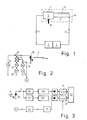
- the known arrangement shown in FIG. 1 consists of sensor 1, transmitter 2 and receiver 3, which are connected to sensor 1 via optical fibers 4 and 5, respectively.
- the optical damping behavior of the transducer 6 is dependent on the measured variable M (eg pressure).
- M eg pressure
- the modulated transmission beam supplied via the FO 4 is divided in the converter into two partial beams, the first of which influenced as much as possible by the measured variable and is conducted into the fiber optic cable 5 via the line 7 and the optical coupler 8.
- the second partial beam (reference beam) which is influenced as little as possible or in the opposite direction to the first partial beam by the measured variable and can also be guided past the converter 6, is passed through the delay line 9 to the coupler 8 and then into the fiber optic cable 5.
- the sum signal is received by the receiver 3, processed and evaluated to form a display representing the measured value M.
- the delay line 9 causes the phases and amplitudes of the modulations of the two partial beams to be different from one another. Any other delay elements could be used instead of a delay line, e.g. luminescent crystals (see Electronics Letters l7, l98l, p. 630).
- the light intensity transmitted by the LED 10 is modulated with high frequency, in particular 100-100 MHz, and low frequency with preferably 0.5 to 2 kHz.
- modulation currents are superimposed on the direct current generated by the direct current source 11 via the superposition element l3.
- the modulation currents are caused by a high-frequency voltage source l4, a low-frequency voltage source l5 and DC voltage sources l6 and l7.
- the voltage sources l4 or l5 can generate sinusoidal or rectangular signals depending on the desired signal profile.
- the optoelectronic converter 18 (photodiode) of the receiver circuit according to FIG. 3 converts the modulated light supplied via the LWL 5 into the same electrical signals in the intensity curve of the light. In addition, however, a dark current I D is superimposed. Through the condens sator C any existing light components of the transmitted signal and the dark current of the optoelectronic converter 18 are blocked.
- the high-pass HP passes the amplified high-frequency modulation signal after peak value rectification into the sample and hold circuit 19 and the low-frequency modulation signal via the low pass TP after amplification and peak value rectification into the sample and hold circuit 20.
- the sample and hold circuits 19 and 20 become clocked with the low-frequency modulation period over the line a coming from the transmitter circuit.
- a delay element 2l enables a desired assignment of the measuring time relative to the maximum of the low-frequency modulation. If the low-frequency modulation is not itself rectangular, 22 rectangular output signals are generated by the threshold switch.
- the evaluation circuit 23 finally decodes the different-frequency modulation signals, so that information proportional to the measured value M can be obtained.
- Circuits which produce rectangular low-frequency modulations in accordance with the signal profiles shown in FIGS. 4 and 5 are particularly simple to implement.
- Transmission times during which high-frequency pulses are transmitted are followed by pauses during which no high-frequency pulses are transmitted.
- Broadcast times and break times can be of different lengths. It is important, however, that the high-frequency modulation frequency HF is much larger than the low-frequency modulation frequency NF or as the low clock frequency of the successive transmission and pause times.
- FIGS. 4, 5 and 6 show signal forms in which the amplitudes of the high-frequency modulations on the transmitter side are twice as large as the amplitudes of the low-frequency modulations.
- the transmission of the offset component I OF as a low-frequency signal gives the advantage that its amplitude can be separated from the constant light components. In particular, dark currents I D of a photodiode of the receiver cannot falsify the value of the offset component.
- FIGS. 4 and 5 each show optical pulse curves on the transmitter side, while on the right-hand side the associated electrical output signals formed by the photodiode 18 are shown.
- the LED l0 whose characteristic 24 has a curved profile, is operated with a control current i 1, which has a time-independent constant component, which causes a constant light I G.
- the LED is operated in an almost linear region of the characteristic curve 24, so that the modulation half-waves are the same.
- Blocks of high-frequency successive pulses are superimposed on the constant component, which cause sinusoidal intensity fluctuations of the transmitted light with the amplitude I HF , which are superimposed on the constant light component I G with an offset intensity I OF .
- the electrical output signal of the photodiode l8 then contains a direct component I ' G , which additionally contains the dark current I D of the photodiode l8.
- a splitting of these current components is not necessary, however, since only the offset component I ' OF is evaluated, which is proportional to the transmitted offset component I OF , unaffected by the dark current I D.
- the value I ' OF is influenced by the measured value M, but not by the delay line 9, while the received signal I' HF additionally due to the effect of the delay line 9 in the relative size Offset portion is reduced.
- the received degree of modulation m 1 has thus changed compared to the transmitted. The extent of this change contains clear information about the measured variable M to be determined.
- the high-frequency modulation in the manner described in FIG. 4 could also take place on the transmitter side with a rectangular profile if a corresponding generator 14 is constructed in a simple manner using toggle switches.
- An evaluation can also be carried out on the receiver side with a circuit according to FIG. 3 if the high-pass filter HP is designed as a band-pass filter, so that only the fundamental harmonic of the rectangular high-frequency transmission modulation is evaluated.
- Transmission T is the ratio of the intensity occurring at the end of a transmission path to the original intensity at the beginning of the transmission path.
- At ⁇ L (2k + l) or if this condition is at least approximated, the greatest measurement sensitivity results.
Abstract
Die Erfindung bezieht sich auf ein Verfahren zur Ermittlung von Meßdaten über eine optische Übertragungsstrecke mittels eines optischen Sensors, welcher einen optischen Wandler enthält, dessen optischen Dämpfungseigenschaften meßwertabhängig beeinflußbar sind und durch welche ein ersten Teilstrahl eines hochfrequent amplitudenmodulierten optischen Sendestrahls geleitet wird, während ein zweiter Teilstrahl dieses Sendestrahls über ein Verzögerungselement umgeleitet und gemeinsam mit dem den optischen Wandler verlassenden ersten Teilstrahl über die Übertragungsstrecke als Empfangsstrahl einer Empfangseinrichtung zugeführt wird, durch welche die vom Sensor bewirkte Modulationsänderung als Information über die Meßgröße aufbereitet und ausgewertet wird.
Eine senderseitige Meßwerterfassung ist bei beliebigen optischen Übertragungsstrecken unbestimmter Länge ohne Nachkalibrierung der Empfangseinrichtung dadurch möglich, daß der optische Sendestrahl zusätzlich niederfrequent moduliert wird, daß ein ursprünglicher Modulationsgrad mo des Sendestrahls als Quotient der hochfrequenten (IHF) zur niederfrequenten (INF) Modulationsamplituden fest vorgegeben und der Empfangseinrichtung 3 als Information eingegeben wird, daß der durch den Sensor beeinflußte empfangene Modulationsgrad des Empfangsstrahls von der Empfangseinrichtung 3 gemessen und das Verhältnis von empfangenem und ursprünglichem Modulationssignal als Information über den Meßwert (M) ausgewertet wird. 
A transmitter-side measurement value acquisition is possible for any optical transmission paths of indefinite length without recalibrating the receiving device in that the optical transmission beam is additionally modulated at low frequency, in that an original degree of modulation m o of the transmission beam is fixed as a quotient of the high-frequency (I HF ) to the low-frequency (I NF ) modulation amplitudes is specified and the receiving device 3 is entered as information that the received degree of modulation of the received beam influenced by the sensor is measured by the receiving device 3 and the ratio of the received and original modulation signal is evaluated as information about the measured value (M).
Description
Die Erfindung bezieht sich auf ein Verfahren zur Ermittlung von Meßdaten über eine optische Übertragungsstrecke mittels eines optischen Sensors, welcher einen optischen Wandler enthält, dessen optischen Dämpfungseigenschaften meßwertabhängig beeinflußbar sind und durch welchen ein erster Teilstrahl eines hochfrequent amplitudenmodulierten optischen Sendestrahls geleitet wird, während ein zweiter Teilstrahl dieses Sendestrahls über ein Verzögerungselement umgeleitet und gemeinsam mit dem den optischen Wandler verlassenden ersten Teilstrahl über die Übertragungsstrecke als Empfangsstrahl einer Empfangseinrichtung zugeführt wird, durch welche die vom Sensor bewirkte Modulationsänderung als Information über die Meßgröße aufbereitet und ausgewertet wird.The invention relates to a method for determining measurement data over an optical transmission path by means of an optical sensor which contains an optical transducer, the optical damping properties of which can be influenced as a function of the measured value and through which a first partial beam of a high-frequency amplitude-modulated optical transmission beam is guided, while a second partial beam this transmission beam is diverted via a delay element and, together with the first partial beam leaving the optical converter, is fed as a reception beam via the transmission path to a receiving device, by means of which the modulation change caused by the sensor is processed and evaluated as information about the measured variable.
Ein derartiges Verfahren ist in "Proceedings of the 2nd International Conference on Fiber Optic Sensors", Stuttgart l984, S. 387 bis 390 beschrieben. Im bekannten Fall wird einer der Teilstrahlen des Sendestrahls, welcher nicht vom Wandler des Sensors beeinflußt wird, durch eine optische Verzögerungsleitung geführt und zeitversetzt mit dem vom Wandler beeinflußten Teilstrahl wieder vereinigt und in eine der Übertragung zu einer Empfangseinrichtung dienende LWL geleitet. Der durch die Verzögerungsleitung gesendete Teilstrahl bildet einen Referenzstrahl. Die relativen Phasenwinkel der Modulationsanteile der beiden Teilstrahlen sind unterschiedlich. Der resultierende Phasenwinkel des empfangenen Strahls wird mit dem Ursprungsphasenwinkel des Sendestrahls verglichen. Aus dem Differenzwinkel bzw. der Phasenverschiebung läßt sich eine Aussage über den Meßwert ableiten welche von evtl. Schwankungen der Dämpfung der Übertragungsstrecke vom und und bis zum Sender unabhängig ist. Allerdings muß die gesamte Länge der Übertragungsstrecke von der Lichtquelle zum Sensor und vom Sensor zur Empfangseinrichtung bekannt sein, da nur unter dieser Voraussetzung die Größe des Meßwerts aus dem Differenzwinkel ermittelt werden kann. Bei einer Änderung der Gesamtlänge der optischen Ubertragungsstrecke muß die Empfangseinrichtung neu kalibriert werden.Such a method is described in "Proceedings of the 2nd International Conference on Fiber Optic Sensors", Stuttgart l984, pp. 387 to 390. In the known case, one of the partial beams of the transmitted beam, which is not influenced by the transducer of the sensor, is guided through an optical delay line and combined with the time delay with the partial beam influenced by the transducer, and is guided into an optical fiber which is used for transmission to a receiving device. The partial beam sent through the delay line forms a reference beam. The relative phase angles of the modulation components of the two partial beams are different. The resulting phase angle of the received beam is compared with the original phase angle of the transmitted beam. From the difference angle or the phase shift, a statement about the measured value can be derived which of any fluctuations in the attenuation of the transmission link from and and is independent until the transmitter. However, the entire length of the transmission path from the light source to the sensor and from the sensor to the receiving device must be known, since only under this condition can the size of the measured value be determined from the difference angle. If the total length of the optical transmission link changes, the receiving device must be recalibrated.
Der Erfindung liegt die Aufgabe zugrunde, das Verfahren der eingangs genannten Art derart zu gestalten, daß eine senderseitige Meßwerterfassung bei beliebigen optischen Übertragungsstrecken unbestimmter Länge ohne Nachkalibrierung der Empfangseinrichtung möglich ist.The invention is based on the object of designing the method of the type mentioned at the outset in such a way that transmitter-side measurement value acquisition is possible for any optical transmission links of indefinite length without recalibration of the receiving device.
Die Lösung gelingt dadurch, daß der optische Sendestrahl zusätzlich niederfrequent amplitudenmoduliert wird, daß ein ursprünglicher Modulationsgrad mo des Sendestrahls als Quotient der niederfrequenten zur hochfrequenten Modulationsamplituden fest vorgegeben und der Empfangseinrichtung als Information eingegeben wird, daß der durch den Sensor beeinflußte empfangene Modulationsgrad m₁ des Empfangsstrahls von der Empfangseinrichtung gemessen und das Verhältnis von empfangenem und ursprünglichem Modulationssignal als Information über den Meßwert ausgewertet wird.The solution is achieved in that the optical transmission beam is additionally amplitude-modulated at low frequency, that an original degree of modulation mo of the transmission beam is fixed as the quotient of the low-frequency to high-frequency modulation amplitudes and the receiving device is entered as information that the received modulation degree m 1 of the reception beam influenced by the sensor measured by the receiving device and the ratio of received and original modulation signal is evaluated as information about the measured value.
Theoretische Überlegungen zeigen, daß das Verhältnis der Modulationsgrade der beiden Teilstrahlen nicht nur von der Dämpfung der Übertragungsstrecke, sondern auch von deren Länge unabhängig ist. Mittels der erfindungsgemäß vorgesehenen Doppelmodulation mit erheblich voneinander abweichenden Frequenzen ist es möglich, aus den empfangenen optischen Signalen den vom Sender geänderten Modulationsgrad m₁ zuverlässig zu ermitteln, ohne daß dabei Verfälschungen durch den Dunkelstrom eines Photodetektors entstehen können.Theoretical considerations show that the ratio of the degrees of modulation of the two partial beams is not only independent of the attenuation of the transmission path, but also of its length. By means of the double modulation provided according to the invention with significantly different frequencies, it is possible to reliably determine the modulation level m 1 changed by the transmitter from the optical signals received, without falsifications being caused by the dark current of a photodetector.
Damit sich für die niederfrequente Modulation praktisch kein Phasenunterschied auf den beiden Teilstrahlen ergibt, ist es vorteilhaft, daß die Modulationsfrequenzen der hochfrequenten und der niederfrequenten Modulationen im Verhältnis von mindestens l0³ unterschiedlich sind.So that there is practically no phase difference on the two partial beams for the low-frequency modulation, it is advantageous that the modulation frequencies of the high-frequency and the low-frequency modulations are different in the ratio of at least 10 3.
Gemäß einer vorteilhaften Ausführungsart der Erfindung ist vorgesehen, daß das hochfrequente Modulationssignal mit dem niederfrequenten Modulationssignal multipliziert ist und daß die Spitzenwerte der durch Filter separierten Modulationssignale ermittelt werden.According to an advantageous embodiment of the invention, it is provided that the high-frequency modulation signal is multiplied by the low-frequency modulation signal and that the peak values of the modulation signals separated by filters are determined.
Dadurch, daß die Modulationsamplituden der hochfrequenten Modulation doppelt so groß wie die der niederfrequenten Modulation gewählt wird, läßt sich mit einfachen schaltungstechnischen Mitteln ein stets gleichbleibend konstanter ursprünglicher Modulationsgrad mo vorgeben.Because the modulation amplitudes of the high-frequency modulation are chosen to be twice as large as those of the low-frequency modulation, a simple, constant circuitry means that an always constant, original degree of modulation m o can be specified.
Besonders einfach sind Modulationen mit rechteckförmigen Verläufen schaltungsmäßig zu realisieren.In terms of circuitry, modulations with rectangular courses are particularly simple to implement.
Einfache Schaltungsaufbauten ergeben sich auch dann, wenn die hochfrequente Modulation nur den positiven Bereich der niederfrequenten Modulation überlagert. Dabei ist es nicht erforderlich, daß die Zeitdauer der positiven Halbwelle der niederfrequenten rechteckförmigen Modulation der Zeitdauer der negativen Halbwelle gleich ist. Vorteilhaft ist es jedoch, daß die überlagerte hochfrequente Modulation aus symmetrischen positiven und negativen Halbwellen besteht. Das ist bei rechteckförmigen Modulationen unabhängig von jeweiligen Krümmungen der Kennlinie einer LED prinzipiell gewährleistet.Simple circuit designs also result when the high-frequency modulation only overlaps the positive range of the low-frequency modulation. It is not necessary that the duration of the positive half-wave of the low-frequency rectangular modulation be the same as the duration of the negative half-wave. However, it is advantageous that the superimposed high-frequency modulation consists of symmetrical positive and negative half-waves. In principle, this is guaranteed with rectangular modulations regardless of the curvature of the characteristic curve of an LED.
Eine besonders einfache Möglichkeit zur Bildung eines bekannten und gleichbleibenden Modulationsgrades ergibt sich dadurch, daß vom Sender Gruppen von optischen Rechteckimpulsen mit einem Tastverhältnis l:l gesendet werden, und daß auf die Sendezeit einer Gruppe eine Pausenzeit folgt, deren Länge ein Vielfaches der Periodendauer der Rechteckimpulse beträgt.A particularly simple possibility for forming a known and constant degree of modulation results from the fact that the transmitter sends groups of optical square-wave pulses with a pulse duty factor 1: 1. and that the transmission time of a group is followed by a pause, the length of which is a multiple of the period of the rectangular pulses.
Mit dem erfindungsgemäßen Verfahren erreicht man eine besonders hohe Meßempfindlichkeit, wenn die Länge der Verzögerungsleitung etwa ein ungerades Vielfaches einer halben Wellenlänge der hochfrequenten Modulation ist.A particularly high measurement sensitivity is achieved with the method according to the invention if the length of the delay line is approximately an odd multiple of half a wavelength of the high-frequency modulation.
Die Erfindung wird anhand der Beschreibung von in der Zeichnung dargestellten vorteilhaften Ausführungsbeispielen näher erläutert.
- Figur l zeigt eine Prinzipanordnung zur Ermittlung von Meßdaten mittels eines optischen Sensors unter Verwendung einer optischen Verzögerungsleitung
Figur 2 zeigt das Blockschaltbild einer für das erfindungsgemäße Verfahren geeigneten SenderschaltungFigur 3 zeigt das Blockschaltbild einer für das erfindungsgemäße Verfahren geeigneten EmpfängerschaltungFigur 4 zeigt Signalverläufe für eine erste Ausführungsart der ErfindungFigur 5 zeigt Signalverläufe für eine zweite Ausführungsart der ErfindungFigur 6 zeigt einen Verlauf der Sendesignale für eine dritte Ausführungsart der Erfindung.
- FIG. 1 shows a basic arrangement for determining measurement data by means of an optical sensor using an optical delay line
- FIG. 2 shows the block diagram of a transmitter circuit suitable for the method according to the invention
- FIG. 3 shows the block diagram of a receiver circuit suitable for the method according to the invention
- Figure 4 shows waveforms for a first embodiment of the invention
- Figure 5 shows waveforms for a second embodiment of the invention
- FIG. 6 shows a course of the transmission signals for a third embodiment of the invention.
Die in Figur l dargestellte bekannte Anordnung besteht aus dem Sensor l, dem Sender 2 und dem Empfänger 3, welche über Lichtwellenleiter 4 bzw. 5 mit dem Sensor l verbunden sind. Das optische Dämpfungsverhalten des Wandlers 6 ist von der Meßgröße M (z.B. Druck) abhängig. Der über die LWL 4 zugeführte modulierte Sendestrahl wird im Wandler in zwei Teilstrahlen aufgeteilt, von welchen der erste möglichst stark von der Meßgröße beeinflußt und über die Leitung 7 und den optischen Koppler 8 in den LWL 5 geleitet wird. Der zweite Teilstrahl (Referenzstrahl), welcher möglichst wenig oder gegenläufig zum ersten Teilstrahl von der Meßgröße beeinflußt ist und auch am Wandler 6 vorbeigeführt werden kann, wird durch die Verzögerungsleitung 9 auf den Koppler 8 und dann in den LWL 5 geleitet. Das Summensignal wird vom Empfänger 3 empfangen, aufbereitet und ausgewertet zur Bildung einer den Meßwert M wiedergebenden Anzeige.The known arrangement shown in FIG. 1 consists of sensor 1,
Die Verzögerungsleitung 9 bewirkt, daß die Phasen und Amplituden der Modulationen der beiden Teilstrahlen verschieden voneinander sind. Statt einer Verzögerungsleitung könnten auch beliebige andere Verzögerungselemente eingesetzt werden, wie z.B. lumineszierende Kristalle (vergl. Electronics Letters l7, l98l, S. 630).The
Mit der in Figur 2 dargestellten Senderschaltung wird die von der LED l0 gesendete Lichtintensität hochfrequent mit insbesondere l0-l00 MHz und niederfrequent mit vorzugsweise 0,5 bis 2 kHz moduliert. Dem von der Gleichstromquelle ll erzeugten Gleichstrom werden an der Stelle l2 Modulationsströme über das Überlagerungsglied l3 überlagert. Die Modulationsströme werden durch eine hochfrequente Spannungsquelle l4, eine niederfrequente Spannungsquelle l5 und Gleichspannungsquellen l6 bzw. l7 hervorgerufen. Die Spannungsquellen l4 bzw. l5 können je nach gewünschtem Signalverlauf sinusförmige oder rechteckförmige Signale erzeugen.With the transmitter circuit shown in FIG. 2, the light intensity transmitted by the
Der optoelektronische Wandler l8 (Photodiode) der Empfängerschaltung nach Figur 3 wandelt das über den LWL 5 zugeführte modulierte Licht in dem Intensitätsverlauf des Lichts gleiche elektrische Signale um. Zusätzlich ist jedoch ein Dunkelstrom ID überlagert. Durch den Konden sator C werden evtl. vorhandene Gleichlichtanteile des Sendesignals und der Dunkelstrom des optoelektronischen Wandlers l8 abgeblockt. Durch den Hochpaß HP gelangt das verstärkte hochfrequente Modulationssignal nach Spitzenwertgleichrichtung in die Sample and Hold-Schaltung l9 und das niederfrequente Modulationssignal über den Tiefpaß TP nach Verstärkung und Spitzenwertgleichrichtung in die Sample and Hold-Schaltung 20. Die Sample and Hold-Schaltungen l9 und 20 werden mit der niederfrequenten Modulationsperiode über die von der Senderschaltung kommende Leitung a getaktet. Ein Verzögerungselement 2l ermöglicht eine gewünschte Zuordnung der Meßzeit relativ zum Maximum der niederfrequenten Modulation. Falls die niederfrequente Modulation nicht an sich schon rechteckförmig verläuft, werden durch den Schwellwertschalter 22 rechteckförmige Ausgangssignale erzeugt.The optoelectronic converter 18 (photodiode) of the receiver circuit according to FIG. 3 converts the modulated light supplied via the
Die Auswerteschaltung 23 dekodiert schließlich die verschiedenfrequenten Modulationssignale, so daß eine dem Meßwert M proportionale Information erhalten werden kann.The
Mit den in den Figuren 2 und 3 dargestellten Schaltungen sind verschiedene Signalformen mit erfindungsgemäß doppelter Modulation übertragbar und auswertbar.With the circuits shown in FIGS. 2 and 3, different signal forms with double modulation according to the invention can be transmitted and evaluated.
Bei entsprechender Gestaltung der Generatoren l4 und l5 (Figur 2) können beispielsweise kontinuierlich sinusförmig verlaufende Signalformen aufmoduliert werden. Dann ergibt sich beispielsweise ein Verlauf des Sendesignals nach Figur 6, wenn gleichzeitig das Übertragungsglied l3 in Figur 2 als Multiplikator ausgebildet ist.With a corresponding design of the generators 14 and 15 (FIG. 2), for example, continuously sinusoidal signal shapes can be modulated. Then, for example, there is a profile of the transmission signal according to FIG. 6, if the transmission element l3 in FIG. 2 is simultaneously designed as a multiplier.
Besonders einfach sind Schaltungen zu realisieren, welche rechteckförmige niederfrequente Modulationen erzeugen entsprechend den in den Figuren 4 und 5 dargestellten Signalverläufen.Circuits which produce rectangular low-frequency modulations in accordance with the signal profiles shown in FIGS. 4 and 5 are particularly simple to implement.
Auf Sendezeiten, während welcher hochfrequente Impulse gesendet werden, folgen Pausenzeiten, während welcher keine hochfrequenten Impulse übertragen werden. Sendezeiten und Pausenzeiten dürfen verschieden lang sein. Wichtig ist jedoch, daß die hochfrequente Modulationsfrequenz HF sehr viel größer als die niederfrequente Modulationsfrequenz NF bzw. als die niedrige Taktfrequenz der aufeinanderfolgenden Sende- und Pausenzeiten ist.Transmission times during which high-frequency pulses are transmitted are followed by pauses during which no high-frequency pulses are transmitted. Broadcast times and break times can be of different lengths. It is important, however, that the high-frequency modulation frequency HF is much larger than the low-frequency modulation frequency NF or as the low clock frequency of the successive transmission and pause times.
In den Figuren 4, 5 und 6 sind Signalformen dargestellt, bei welchen senderseitig die Amplituden der hochfrequenten Modulationen doppelt so groß wie die Amplituden der niederfrequenten Modulationen sind. Der ursprüngliche gesendete Modulationsgrad ist dann mo = 0,5. Dieser Wert ist durch die Senderschaltung schaltungsbedingt fest und unveränderbar vorgegeben, so daß empfängerseitig der Wert mo = 0,5 als konstante Größe voraussetzbar ist. Die Senderschaltung ist dann jeweils so gestaltet, daß einem zeitlich unveränderlichen Basisniveau bzw. Gleichlicht IG, welches auch den Wert "Null" annehmen kann, ein hochfrequent intensitätsmoduliertes Wechsellicht mit der Amplitude IHF bei einem Offset-Anteil von stets IOF = IHF überlagert ist, wobei während gewisser Zeitintervalle (Pausenzeiten) die Amplitude IHF den Wert "Null" annehmen muß. Der Offset-Anteil IOF wird als niederfrequentes Modulationssignal IOF = 2 INF übertragen. Das kann entweder mit einem sinusförmigen Verlauf gemäß Figur 6 oder mit rechteckigem Verlauf gemäß den linken Seiten der Figur 4 oder 5 erfolgen. Die Übertragung des Offset-Anteils IOF als niederfrequentes Signal ergibt den Vorteil, daß dessen Amplitude vom Gleichlichtanteilen trennbar ist. Insbesondere können Dunkelströme ID einer Photodiode des Empfängers den Wert des Offset-Anteils nicht verfälschen.FIGS. 4, 5 and 6 show signal forms in which the amplitudes of the high-frequency modulations on the transmitter side are twice as large as the amplitudes of the low-frequency modulations. The original degree of modulation sent is then m o = 0.5. This value is fixed and unchangeable by the transmitter circuit due to the circuit, so that the value m o = 0.5 can be assumed as a constant value on the receiver side. The transmitter circuit is then designed such that a basic level or constant light I G , which cannot change over time, which can also assume the value "zero", is a high-frequency intensity-modulated alternating light with the amplitude I HF with an offset component of always I OF = I HF is superimposed, the amplitude I HF having to assume the value "zero" during certain time intervals (break times). The offset component I OF is transmitted as a low-frequency modulation signal I OF = 2 I NF . This can be done either with a sinusoidal curve according to FIG. 6 or with a rectangular curve according to the left sides of FIG. 4 or 5. The transmission of the offset component I OF as a low-frequency signal gives the advantage that its amplitude can be separated from the constant light components. In particular, dark currents I D of a photodiode of the receiver cannot falsify the value of the offset component.
Da andererseits die Frequenz der niederfrequenten Modulation sehr niedrig ist, werden die Offset-Anteile IF auf den beiden Wegen 7 und 9 (Figur l) der Teilstrahlen praktisch nicht relativ zueinander phasenverschoben. Diesbezüglich besteht praktisch kein Unterschied gegenüber Gleichlichtanteilen.On the other hand, since the frequency of the low-frequency modulation is very low, the offset components I F on the two paths 7 and 9 (FIG. 1) of the partial beams are practically not phase-shifted relative to one another. In this regard there is practically no difference compared to constant light components.
Die linken Seiten der Figuren 4 und 5 zeigen jeweils senderseitige optische Impulsverläufe, während rechts davon die empfängerseitig von der Photodiode l8 gebildeten zugehörigen elektrischen Ausgangssignale dargestellt sind.The left-hand sides of FIGS. 4 and 5 each show optical pulse curves on the transmitter side, while on the right-hand side the associated electrical output signals formed by the photodiode 18 are shown.
Gemäß Figur 4 wird die LED l0, deren Kennlinie 24 einen gekrümmten Verlauf hat, mit einem Steuerstrom i₁ betrieben, welcher einen zeitunabhängig konstanten Anteil aufweist, welcher ein Gleichlicht IG bewirkt. Infolge dieses konstanten Offset-Anteils wird die LED in einem nahezu linearen Bereich der Kennlinie 24 betrieben, so daß die Modulationshalbwellen gleich sind. Dem konstanten Anteil sind Blöcke von hochfrequent aufeinanderfolgenden Impulsen überlagert, welche sinusförmige Intensitätsschwankungen des gesendeten Lichts mit der Amplitude IHF bewirken, die mit einer Offset-Intensität IOF dem Gleichlichtanteil IG überlagert sind.According to Figure 4, the LED l0, whose characteristic 24 has a curved profile, is operated with a control current i 1, which has a time-independent constant component, which causes a constant light I G. As a result of this constant offset component, the LED is operated in an almost linear region of the
Das elektrische Ausgangssignal der Photodiode l8 enthält dann einen Gleichanteil I′G, welcher zusätzlich den Dunkelstrom ID der Photodiode l8 beinhaltet. Eine Aufspaltung dieser Stromanteile ist jedoch nicht erforderlich, da lediglich der Offset-Anteil I′OF ausgewertet wird, welcher dem gesendeten Offset-Anteil IOF, unbeeinflußt durch den Dunkelstrom ID, proportional ist. Der Wert I′OF ist vom Meßwert M, aber nicht von der Verzögerungsleitung 9 beeinflußt, während das Empfangssignal I′HF zusätzlich infolge der Wirkung der Verzögerungsleitung 9 in der relativen Größe zum Offset-Anteil verkleinert ist. Der empfangene Modulationsgrad m₁ hat sich also gegenüber dem gesendeten verändert. Das Ausmaß dieser Veränderung beinhaltet eine eindeutige Information über die zu ermittelnde Meßgröße M.The electrical output signal of the photodiode l8 then contains a direct component I ' G , which additionally contains the dark current I D of the photodiode l8. A splitting of these current components is not necessary, however, since only the offset component I ' OF is evaluated, which is proportional to the transmitted offset component I OF , unaffected by the dark current I D. The value I ' OF is influenced by the measured value M, but not by the
Die hochfrequente Modulation könnte in der gemäß Figur 4 beschriebenen Art senderseitig auch mit rechteckförmigem Verlauf erfolgen, wenn ein entsprechender Generator l4 in einfacher Weise unter Verwendung von Kippschaltungen aufgebaut wird. Eine Auswertung kann empfängerseitig ebenfalls mit einer Schaltung nach Figur 3 durchgeführt werden, wenn der Hochpaß HP als Bandpaß ausgebildet ist, so daß lediglich die Grundharmonische der rechteckförmigen hochfrequenten Sendemodulation ausgewertet wird.The high-frequency modulation in the manner described in FIG. 4 could also take place on the transmitter side with a rectangular profile if a corresponding generator 14 is constructed in a simple manner using toggle switches. An evaluation can also be carried out on the receiver side with a circuit according to FIG. 3 if the high-pass filter HP is designed as a band-pass filter, so that only the fundamental harmonic of the rectangular high-frequency transmission modulation is evaluated.
Eine besonders einfache und bevorzugte Ausführungsart der Erfindung wird mit in Figur 5 dargestellten Signalverläufen ermöglicht. Dort wird der Ansteuerstrom i₂ in von Pausenzeiten beabstandeten Blöcken mit einem Tastverhältnis "eins" hochfrequent rechteckförmig gepulst. Unabhängig von der Krümmung der LED-Kennlinie 24 ergeben sich stets rechteckförmige optische Modulationssignale mit einem Tastverhälnis "eins", so daß die Bedingung IHF = IOF genau eingehalten ist.A particularly simple and preferred embodiment of the invention is made possible with the signal profiles shown in FIG. There the drive current i₂ is pulsed in a high-frequency rectangular shape in blocks spaced apart from break times with a pulse duty factor "one". Regardless of the curvature of the LED characteristic 24, rectangular optical modulation signals with a duty cycle "one" always result, so that the condition I HF = I OF is met exactly.
Die auf der rechten Seite der Figur 5 dargestellten elektrischen Ausgangssignale der Photodiode l8 haben unter der Voraussetzung, daß die Länge Δ L der Verzögerungsleitung 9 ein ungerades Vielfaches der Hälfte der Modulationswellenlänge beträgt (Δ L = (2k + l) ![]()
![]()
Je nach der Modulationsfrequenz ωHF und der zugehörigen Wellenlänge λ ergeben sich dann typische Werte der Länge Δ L der Verzögerungsleitung wie folgt:
L = l m für λ = 2 m und ωHF = l00 MHz
L =l0 m für λ =20 m und ωHF = l0 MHz.Depending on the modulation frequency ω HF and the associated wavelength λ, typical values of the length Δ L of the delay line then result as follows:
L = lm for λ = 2 m and ω HF = 100 MHz
L = 10 m for λ = 20 m and ω HF = 10 MHz.
Der für die Ermittlung der Meßgröße M benötigte Quotient der Transmissionen T₁ und T₂ der Teilwege über die Verzögerungsleitung 9 bzw. über den direkten Weg 7 ergibt sich aus der Gleichung
Als Transmission T wird in üblicher Weise das Verhältnis der am Ende einer Transmissionsstrecke auftretenden Intensität zu der am Anfang der Übertragungsstrecke vorhandenen ursprünglichen Intensität bezeichnet.Transmission T is the ratio of the intensity occurring at the end of a transmission path to the original intensity at the beginning of the transmission path.
BeiΔ L = (2k + l) ![]()
![]()
Claims (10)
dadurch gekennzeichnet, daß der optische Sendestrahl zusätzlich niederfrequent moduliert wird, daß ein ursprünglicher Modulationsgrad mo des Sendestrahls als Quotient der niederfrequenten (INF) zur hochfrequenten (IHF) Modulationsamplituden fest vorgegeben und der Empfangseinrichtung 3 als Information eingegeben wird, daß der durch den Sensor beeinflußte empfangene
Modulationsgrad m₁ =
des Empfangsstrahls von der Empfangseinrichtung 3 gemessen und das Verhältnis von empfangenem und ursprünglichem Modulationssignal als Information über den Meßwert (M) ausgewertet wird.1.Method for determining measurement data over an optical transmission path by means of an optical sensor which contains an optical converter, the optical damping properties of which can be influenced as a function of the measured value and through which a first partial beam of a high-frequency amplitude-modulated optical transmission beam is guided, while a second partial beam of this transmission beam is directed via a Redirected the delay element and, together with the first partial beam leaving the optical converter, is fed via the transmission path as a receiving beam to a receiving device, by means of which the modulation change caused by the sensor is processed and evaluated as information about the measured variable,
characterized in that the optical transmission beam is additionally modulated at low frequency, that an original degree of modulation m o of the transmission beam as the quotient of the low-frequency (I NF ) to the high-frequency (I HF ) modulation amplitudes is fixed and the receiving device 3 is entered as information that the by Sensor affected received
Degree of modulation m₁ =
of the received beam is measured by the receiving device 3 and the ratio of the received and original modulation signal is evaluated as information about the measured value (M).
dadurch gekennzeichnet, daß die Modulationsfrequenzen des hochfrequenten (ωHF) und der niederfrequenten (ωNF) Modulationen im Verhältnis von mindestens l0³ unterschiedlich sind.2. The method according to claim 1,
characterized in that the modulation frequencies of the high-frequency (ω HF ) and the low-frequency (ω NF ) modulations are different in the ratio of at least 10 3.
dadurch gekennzeichnet, daß das hochfrequente Modulationssignal mit dem niederfrequenten Modulationssignal multipliziert ist und daß die Spitzenwerte der durch Filter separierten Modulationssignale ermittelt werden.3. The method according to claim l or 2,
characterized in that the high-frequency modulation signal is multiplied by the low-frequency modulation signal and in that the peak values of the modulation signals separated by filters are determined.
dadurch gekennzeichnet, daß die Modulationsamplitude (IHF) der hochfrequenten Modulation doppelt so groß wie die Amplitude (INF) der niederfrequenten Modulation ist.4. The method according to any one of claims 1 to 3,
characterized in that the modulation amplitude (I HF ) of the high-frequency modulation is twice as large as the amplitude (I NF ) of the low-frequency modulation.
dadurch gekennzeichnet, daß die niederfrequente Modulation rechteckförmig erfolgt.5. The method according to any one of claims 1 to 4,
characterized in that the low-frequency modulation is rectangular.
dadurch gekennzeichnet, daß die hochfrequente Modulation nur dem positiven Bereich der niederfrequenten Modulation überlagert ist.6. The method according to any one of claims 1 to 5,
characterized in that the high-frequency modulation is superimposed only on the positive range of the low-frequency modulation.
dadurch gekennzeichnet, daß die Zeitdauer der positiven Halbwelle der niederfrequenten rechteckförmigen Modulation von der Zeitdauer der negativen Halbwelle abweicht.7. The method according to any one of claims 5 or 6,
characterized in that the duration of the positive half-wave of the low-frequency rectangular modulation deviates from the duration of the negative half-wave.
dadurch gekennzeichnet, daß die überlagerte hochfrequente Modulation aus symmetrischen negativen und positiven Halbwellen besteht.8. The method according to any one of claims 5 to 7,
characterized in that the superimposed high-frequency modulation consists of symmetrical negative and positive half-waves.
dadurch gekennzeichnet, daß vom Sender Gruppen optischer Rechteckimpulse mit einem Tastverhältnis "eins" gesendet werden, und daß auf die Sendezeit einer Gruppe von Rechteck-Impulsen jeweils eine Pausenzeit folgt, deren Länge ein Vielfaches der Periodendauer der Rechteck-Impulse beträgt (Figur 5).9. The method according to any one of claims 5 to 8,
characterized in that groups of optical rectangular pulses with a duty cycle "one" are sent by the transmitter, and in that the transmission time of a group of Rectangular pulses each have a pause time, the length of which is a multiple of the period of the rectangular pulses (FIG. 5).
dadurch gekennzeichnet, daß die Länge der Verzögerungsleitung etwa ein ungerades Vielfaches der Hälfte der hochfrequenten Modulationswellenlänge ist.l0. Method according to one of claims 1 to 9,
characterized in that the length of the delay line is approximately an odd multiple of half the high frequency modulation wavelength.
Applications Claiming Priority (2)
| Application Number | Priority Date | Filing Date | Title |
|---|---|---|---|
| DE19863606488 DE3606488A1 (en) | 1986-02-28 | 1986-02-28 | METHOD FOR DETERMINING MEASURED DATA ON AN OPTICAL TRANSMISSION LINE BY MEANS OF AN OPTICAL SENSOR |
| DE3606488 | 1986-02-28 |
Publications (3)
| Publication Number | Publication Date |
|---|---|
| EP0244883A2 true EP0244883A2 (en) | 1987-11-11 |
| EP0244883A3 EP0244883A3 (en) | 1988-12-28 |
| EP0244883B1 EP0244883B1 (en) | 1991-07-17 |
Family
ID=6295134
Family Applications (1)
| Application Number | Title | Priority Date | Filing Date |
|---|---|---|---|
| EP87200279A Expired - Lifetime EP0244883B1 (en) | 1986-02-28 | 1987-02-20 | Method for data acquisition over an optical transmission line using optical sensors |
Country Status (4)
| Country | Link |
|---|---|
| US (1) | US4850698A (en) |
| EP (1) | EP0244883B1 (en) |
| JP (1) | JPS62204400A (en) |
| DE (2) | DE3606488A1 (en) |
Cited By (2)
| Publication number | Priority date | Publication date | Assignee | Title |
|---|---|---|---|---|
| DE3805328A1 (en) * | 1988-02-20 | 1989-08-31 | Asea Brown Boveri | Method for transmitting measurement values in a transmission of the measurement values by optical fibre |
| DE19548920A1 (en) * | 1994-12-27 | 1996-07-11 | Toshiba Kawasaki Kk | Sensor with optical modulator for process control |
Families Citing this family (9)
| Publication number | Priority date | Publication date | Assignee | Title |
|---|---|---|---|---|
| JP2527829B2 (en) * | 1990-04-25 | 1996-08-28 | 三菱電機株式会社 | Optical application measuring device |
| FR2664048B1 (en) * | 1990-06-29 | 1993-08-20 | Centre Nat Rech Scient | MULTICHANNEL ANALOGUE DETECTION METHOD AND DEVICE. |
| GB9204067D0 (en) * | 1992-02-26 | 1992-04-08 | Sensor Dynamics Ltd | Optical fibre sensor |
| US5535139A (en) * | 1994-04-04 | 1996-07-09 | International Business Machines Corporation | Portable fiber optic splitter tool for multimode optical fiber cable link |
| JP3320996B2 (en) * | 1996-11-26 | 2002-09-03 | 株式会社東芝 | WDM optical transmission equipment |
| DE102004004260B3 (en) * | 2004-01-23 | 2005-06-23 | Fraunhofer-Gesellschaft zur Förderung der angewandten Forschung e.V. | Circuit arrangement for reducing pulsed analog measurement signal measurement errors, has switch defining sampling times of 2 hold elements whose outputs feed difference element that outputs measurement signal integral value |
| CA2684744C (en) * | 2007-04-26 | 2016-06-21 | Tyco Healthcare Group Lp | Multifunctional medical access device |
| DE102011003306B3 (en) * | 2011-01-28 | 2012-04-05 | Siemens Aktiengesellschaft | Circuit arrangement for detecting and digitizing an analog input signal and field device for process instrumentation |
| US9461743B1 (en) * | 2014-07-16 | 2016-10-04 | Rockwell Collins, Inc. | Pulse to digital detection circuit |
Citations (2)
| Publication number | Priority date | Publication date | Assignee | Title |
|---|---|---|---|---|
| DE3217078A1 (en) * | 1981-05-18 | 1982-12-02 | ASEA AB, 72183 Västerås | FIBER OPTICAL MEASUREMENT ARRANGEMENT |
| EP0168182A2 (en) * | 1984-06-14 | 1986-01-15 | National Research Development Corporation | Optical measurement apparatus |
Family Cites Families (1)
| Publication number | Priority date | Publication date | Assignee | Title |
|---|---|---|---|---|
| JPS5897800A (en) * | 1981-12-04 | 1983-06-10 | 松下電器産業株式会社 | Light sensor |
-
1986
- 1986-02-28 DE DE19863606488 patent/DE3606488A1/en not_active Withdrawn
-
1987
- 1987-02-20 EP EP87200279A patent/EP0244883B1/en not_active Expired - Lifetime
- 1987-02-20 DE DE8787200279T patent/DE3771384D1/en not_active Expired - Lifetime
- 1987-02-27 JP JP62043284A patent/JPS62204400A/en active Pending
- 1987-02-27 US US07/020,066 patent/US4850698A/en not_active Expired - Fee Related
Patent Citations (2)
| Publication number | Priority date | Publication date | Assignee | Title |
|---|---|---|---|---|
| DE3217078A1 (en) * | 1981-05-18 | 1982-12-02 | ASEA AB, 72183 Västerås | FIBER OPTICAL MEASUREMENT ARRANGEMENT |
| EP0168182A2 (en) * | 1984-06-14 | 1986-01-15 | National Research Development Corporation | Optical measurement apparatus |
Cited By (3)
| Publication number | Priority date | Publication date | Assignee | Title |
|---|---|---|---|---|
| DE3805328A1 (en) * | 1988-02-20 | 1989-08-31 | Asea Brown Boveri | Method for transmitting measurement values in a transmission of the measurement values by optical fibre |
| DE19548920A1 (en) * | 1994-12-27 | 1996-07-11 | Toshiba Kawasaki Kk | Sensor with optical modulator for process control |
| DE19548920C2 (en) * | 1994-12-27 | 2003-05-28 | Toshiba Kawasaki Kk | Optical sensor and use of such a sensor in a process measuring device |
Also Published As
| Publication number | Publication date |
|---|---|
| DE3606488A1 (en) | 1987-09-03 |
| US4850698A (en) | 1989-07-25 |
| DE3771384D1 (en) | 1991-08-22 |
| JPS62204400A (en) | 1987-09-09 |
| EP0244883A3 (en) | 1988-12-28 |
| EP0244883B1 (en) | 1991-07-17 |
Similar Documents
| Publication | Publication Date | Title |
|---|---|---|
| EP0193242B1 (en) | Optical time-domaine reflectometer with heterodyne receiving | |
| EP0244883B1 (en) | Method for data acquisition over an optical transmission line using optical sensors | |
| WO2004018968A1 (en) | Method and device for optically measuring distance | |
| EP0262461B1 (en) | Ultrasonic fluid flow rate motor using the phase difference method | |
| DE1564450B2 (en) | NOISE-FREE OVERLAY RECEIVER FOR MODULATED COAERENT LIGHT | |
| DE1698279A1 (en) | Method and device for remote measurement using modulated bundles of light | |
| EP0238134A2 (en) | Optical time domain reflectometer with heterodyn-reception | |
| CH616510A5 (en) | ||
| DE69925476T2 (en) | NOISE REDUCTION METHOD AND DEVICE FOR OPTICAL FIBER SENSOR ARRAYS IN TIME MULTIPLEXY OPERATION | |
| DE19537647C1 (en) | Method and arrangement for measuring physical quantities of light-scattering moving particles using a laser Doppler anemometer | |
| EP0113889B1 (en) | Rotation speed measuring apparatus | |
| EP0362474B1 (en) | Laser warning detector | |
| DE2539438B2 (en) | Radiation barrier | |
| DE2521067C3 (en) | Method and device for aligning an electro-optical range finder on the basis of an acoustic auxiliary directional signal | |
| DE4133131C2 (en) | Arrangement for determining chemical and / or physical quantities influencing the light intensity | |
| DE3316630C2 (en) | Device for determining the transit time of ultrasonic pulses in a fluid | |
| EP0231980A2 (en) | Method for transmitting measuring signals of at least two sensors via an opticaltransmission link | |
| DE1931019A1 (en) | Comparison radiometer | |
| DE3743678A1 (en) | OPTICAL BACKFLOW MEASURING DEVICE | |
| EP0222077B1 (en) | Apparatus for measuring rotation speed | |
| DE3244010A1 (en) | Device for measuring rotational speed | |
| DE3409310C2 (en) | ||
| EP0298484A1 (en) | Optical FSK homodyne receiver | |
| DE3708152C2 (en) | ||
| DE2707743C3 (en) | Method for the transmission of information by means of time-modulated pulses |
Legal Events
| Date | Code | Title | Description |
|---|---|---|---|
| PUAI | Public reference made under article 153(3) epc to a published international application that has entered the european phase |
Free format text: ORIGINAL CODE: 0009012 |
|
| AK | Designated contracting states |
Kind code of ref document: A2 Designated state(s): DE FR GB |
|
| PUAL | Search report despatched |
Free format text: ORIGINAL CODE: 0009013 |
|
| AK | Designated contracting states |
Kind code of ref document: A3 Designated state(s): DE FR GB |
|
| 17P | Request for examination filed |
Effective date: 19890614 |
|
| 17Q | First examination report despatched |
Effective date: 19900914 |
|
| GRAA | (expected) grant |
Free format text: ORIGINAL CODE: 0009210 |
|
| AK | Designated contracting states |
Kind code of ref document: B1 Designated state(s): DE FR GB |
|
| REF | Corresponds to: |
Ref document number: 3771384 Country of ref document: DE Date of ref document: 19910822 |
|
| ET | Fr: translation filed | ||
| GBT | Gb: translation of ep patent filed (gb section 77(6)(a)/1977) | ||
| PLBE | No opposition filed within time limit |
Free format text: ORIGINAL CODE: 0009261 |
|
| STAA | Information on the status of an ep patent application or granted ep patent |
Free format text: STATUS: NO OPPOSITION FILED WITHIN TIME LIMIT |
|
| 26N | No opposition filed | ||
| REG | Reference to a national code |
Ref country code: FR Ref legal event code: CD |
|
| PGFP | Annual fee paid to national office [announced via postgrant information from national office to epo] |
Ref country code: GB Payment date: 19960131 Year of fee payment: 10 |
|
| PGFP | Annual fee paid to national office [announced via postgrant information from national office to epo] |
Ref country code: FR Payment date: 19960228 Year of fee payment: 10 |
|
| PGFP | Annual fee paid to national office [announced via postgrant information from national office to epo] |
Ref country code: DE Payment date: 19960424 Year of fee payment: 10 |
|
| PG25 | Lapsed in a contracting state [announced via postgrant information from national office to epo] |
Ref country code: GB Effective date: 19970220 |
|
| GBPC | Gb: european patent ceased through non-payment of renewal fee |
Effective date: 19970220 |
|
| PG25 | Lapsed in a contracting state [announced via postgrant information from national office to epo] |
Ref country code: FR Effective date: 19971030 |
|
| PG25 | Lapsed in a contracting state [announced via postgrant information from national office to epo] |
Ref country code: DE Effective date: 19971101 |
|
| REG | Reference to a national code |
Ref country code: FR Ref legal event code: ST |