EP0244732A2 - Véhicule pour la collecte d'ordures - Google Patents
Véhicule pour la collecte d'ordures Download PDFInfo
- Publication number
- EP0244732A2 EP0244732A2 EP87106110A EP87106110A EP0244732A2 EP 0244732 A2 EP0244732 A2 EP 0244732A2 EP 87106110 A EP87106110 A EP 87106110A EP 87106110 A EP87106110 A EP 87106110A EP 0244732 A2 EP0244732 A2 EP 0244732A2
- Authority
- EP
- European Patent Office
- Prior art keywords
- carrier
- handlebar
- lever
- articulated
- arm
- Prior art date
- Legal status (The legal status is an assumption and is not a legal conclusion. Google has not performed a legal analysis and makes no representation as to the accuracy of the status listed.)
- Granted
Links
- 230000008878 coupling Effects 0.000 claims abstract description 26
- 238000010168 coupling process Methods 0.000 claims abstract description 26
- 238000005859 coupling reaction Methods 0.000 claims abstract description 26
- 239000002699 waste material Substances 0.000 claims abstract description 4
- 230000005540 biological transmission Effects 0.000 claims abstract description 3
- 230000006835 compression Effects 0.000 claims description 5
- 238000007906 compression Methods 0.000 claims description 5
- 210000000078 claw Anatomy 0.000 description 6
- 238000013016 damping Methods 0.000 description 3
- 238000006073 displacement reaction Methods 0.000 description 2
- 238000010009 beating Methods 0.000 description 1
- 230000000295 complement effect Effects 0.000 description 1
- 238000010276 construction Methods 0.000 description 1
- 230000000694 effects Effects 0.000 description 1
Images

Classifications
-
- B—PERFORMING OPERATIONS; TRANSPORTING
- B65—CONVEYING; PACKING; STORING; HANDLING THIN OR FILAMENTARY MATERIAL
- B65F—GATHERING OR REMOVAL OF DOMESTIC OR LIKE REFUSE
- B65F3/00—Vehicles particularly adapted for collecting refuse
- B65F3/02—Vehicles particularly adapted for collecting refuse with means for discharging refuse receptacles thereinto
- B65F3/04—Linkages, pivoted arms, or pivoted carriers for raising and subsequently tipping receptacles
- B65F3/06—Arrangement and disposition of fluid actuators
-
- B—PERFORMING OPERATIONS; TRANSPORTING
- B65—CONVEYING; PACKING; STORING; HANDLING THIN OR FILAMENTARY MATERIAL
- B65F—GATHERING OR REMOVAL OF DOMESTIC OR LIKE REFUSE
- B65F3/00—Vehicles particularly adapted for collecting refuse
- B65F3/02—Vehicles particularly adapted for collecting refuse with means for discharging refuse receptacles thereinto
- B65F2003/0223—Vehicles particularly adapted for collecting refuse with means for discharging refuse receptacles thereinto the discharging means comprising elements for holding the receptacle
- B65F2003/024—Means for locking the rim
Definitions
- the invention relates to a refuse collection vehicle with a pouring unit, consisting of a pouring opening arranged in the front area of the vehicle and a lifting and tipping device for receiving and emptying garbage containers into the pouring opening of a receiving space, the lifting and tilting device pivoting at least one about a transverse axis of the pouring unit or the chassis Lift arm which carries at its free end a base rail parallel to the transverse axis, which can be pivoted between its receiving area in front of the driver's cab and its dumping area behind the driver's cab and on which a carrier can be displaceably supported by at least one end thereof by means of a pressure-piston-cylinder unit is and wherein a pivot arm is mounted on the carrier, which can be pivoted via a handlebar and a pressure-piston-cylinder unit between its folded position on the carrier and its position approximately at right angles to it, and a coupling piece at its free end for coupling and / or gripping Bins.
- the swivel arm forms, together with an auxiliary link articulated at a distance from it on the carrier, with the coupling piece articulated at its outer ends as a coupling member, a four-bar system which is operated by a hydraulic piston-cylinder unit , one end of which is articulated on the support and the other end of which is articulated on the swivel arm, and can be swiveled out and in.
- a pressure medium-piston-cylinder unit is provided, by means of which the carrier is displaced relative to the base rail on which it is guided.
- the object of the invention is therefore to provide a device which is simpler than the known device for extending and pivoting out the coupling piece.
- this object is achieved in a refuse collection vehicle of the generic type in that a link or lever is articulated on the carrier in its front region in the direction of extension, which carries a sliding block or a roller at its free ends, which is connected in a curve guide firmly connected to the base rail run and that with the handlebars or Lever a transmission rod is connected as a gear member, which is directly or indirectly articulated to the swivel arm and this pivots according to the rotation of the handlebar or lever.
- a coupling rod is connected to the handlebar at a distance from its pivot axis, the other end of which is articulated on the pivot arm at a distance from its pivot point on the carrier.
- the pivoting of the swivel arm carrying the coupling piece takes place depending on the displacement of the carrier on the base rail only by the handlebar provided with the roller, which is connected to the swivel arm like a toggle lever by a coupling rod.
- no special drive in the form of a hydraulic cylinder therefore needs to be provided for pivoting the swivel arm carrying the coupling piece. Since the pivoting movement of the pivot arm is derived from the extension movement of the carrier, only a hydraulic cylinder displacing the carrier need be provided.
- the coupling piece expediently consists of a triangular receiving claw with wedge-shaped or spherically curved gripping edges, which can be inserted centering into a complementary receiving pocket of the refuse containers to be gripped, and is preferably rigidly connected to the gripping arm. Since the receiving claw is provided with a substantially flat front surface, this aligns the waste container to be grasped with a slight displacement by pivoting the gripping arm relative to the latter.
- the spring acts as a damping element and prevents the swivel arm from being struck into its swiveled-in end position by the hydraulic cylinder displacing the carrier with excessive force.
- the carrier consists of two telescopically pushed and guided profiled carrier pieces and that two hydraulic piston-cylinder units are arranged in parallel in the inner carrier piece, both of which cylinders are connected to a base plate of the outer carrier piece and one piston rod each is connected to the base rail and an end plate of the inner support piece.
- the lever is designed as a crank mounted in the carrier and that a lever is connected to the crankshaft, the free end of which is articulated to a coupling rod, the other end of which is attached to the swivel arm at a distance from its articulation point is articulated to the carrier.
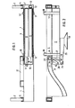
- the base rail 1 is pivoted about axes 4, 5 parallel to it. Furthermore, the base rail 1 is articulated in the manner known from EP-OS 163 859 with an auxiliary linkage which pivots the base rail 1 in accordance with the respective pivot position of the lifting arms 2, 3.
- the carrier piece 6 which has a rectangular box profile, is guided in a longitudinally displaceable manner.
- the carrier piece 7 is telescopically guided, which has a correspondingly smaller box profile.
- the outer Carrier piece 6 is closed on the right side by a bottom 7.
- the cylinders 8, 9 of the hydraulic piston-cylinder units 10, 11, which extend into the profile of the inner support piece 7, are fastened to the base 7.
- the lower cylinder 9 is fastened with its piston end to the base plate 7, while the piston rod 12 passes through the base plate 7 and is fastened to the base rail 1 by the abutment part 13.
- the upper cylinder 8 is fastened to the base plate 7 with its end opposite the piston rod 14.
- the front end of the piston rod 14 is attached to an end plate 15 which closes the front end of the profile of the inner carrier piece 7 at its front end.
- the longitudinally displaceable guidance of the outer carrier piece 6 in the base rail 1 is shown schematically by the tabs 16, 17 fastened to the outer carrier piece 6, which engage behind the base rail 1 with guide rollers 18, 19.
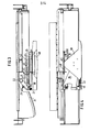
- the link 21 is pivotally articulated about a vertical axis 20 and carries a freely rotatable roller 22 at its free end.
- the pivot arm 25 is furthermore pivotably mounted at a distance from the pivot axis 20 about a vertical axis 24 parallel to this.
- the coupling rod 27 is pivotally mounted thereon, the other end of which is articulated in the joint 28 on the pivot arm 25.
- the pivot arm 25 carries the approximately triangular receiving claw 30 at its outer end.
- the roller 22 mounted on the free end of the handlebar 21 runs in the channel-shaped curve guide 31, which is fixed to the bottom rail 1 is connected. If the carrier pieces 6, 7 are extended to the left by the piston-cylinder units 10, 11, the pivot arm 25 is pivoted clockwise by the link 21 and the coupling rod 27 into its approximately rectangular position with respect to the carrier pieces 8, 9. 1, 2, the support arm 25 is shown in its pivoted-in position, in which the receiving claw 30 is located centrally between the lifting arms 2, 3. In the pivoted-out position (not shown), the area of the inner support piece 7 which carries the joints 20, 21 is extended to the left beyond the lifting arm 2.
- the pivot points 20, 24, 26, 28 of the handlebar 21, the lifting arm 25 and the coupling rod 27 and the curvature of the curve 31 are selected so that the lifting arm 25 is pivoted out in the desired manner by extending the carrier pieces 8, 9.
- the rod 41 is pivotally mounted about the axis 40, which slides through the plate 42, which is fixedly connected to the front region of the pivot arm 25, in a bore.
- the rear end of the rod 41 is connected to an abutment plate 43.
- a helical compression spring 44 is clamped between the abutment plate 43 and the slide plate 42.
- the pivot point 40 of the rod 41 and the bore in the slide plate 42 are selected so that the spring 44 is increasingly tensioned when the lifting arm 25 is pivoted into the pivoted-in end position.
- the spring thus has a damping effect on the piston-cylinder units, so that undesired beating of the swivel arm with high kinetic energy into the swiveled-in end position is avoided.
- Bearing plate 48 is provided, which is supported on the top of the upper edge of the waste container to be emptied.
- This holding plate is pivotally mounted against spring force by a small angle and the end positions of the holding plate are secured by abutments forming stops.
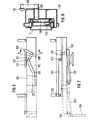
- FIGS. 6 to 8 Another embodiment of the control for the swivel arm 1-25 is described with reference to FIGS. 6 to 8.
- the curve guide 131 is provided in the front end face of the base rail 1.
- a roller 122 runs, which is mounted on the free end of the lever 121, which is fastened to the inner end of the shaft 120 mounted on the telescopic support 107 and thus forms a crank.
- a lever 128 is attached to the outer end of the shaft or crankshaft 120 projecting beyond the telescopic support 7, the free end of which is articulated to a coupling rod 127, the other end of which is articulated to the swivel arm 125 at a distance from its articulation point 124 on the telescopic support 107 is.
- the crank When the supports 106, 107 are extended, the crank thus transmits a connecting rod-like movement to the coupling rod 127, which thus swivels the pivot arm 125 between the end positions of the crank roller 122 in the cam guide 131.
Landscapes
- Engineering & Computer Science (AREA)
- Mechanical Engineering (AREA)
- Refuse-Collection Vehicles (AREA)
- Processing Of Solid Wastes (AREA)
- Filters For Electric Vacuum Cleaners (AREA)
- Braking Arrangements (AREA)
- Treatment Of Sludge (AREA)
- Refuse Collection And Transfer (AREA)
Priority Applications (1)
| Application Number | Priority Date | Filing Date | Title |
|---|---|---|---|
| AT87106110T ATE60021T1 (de) | 1986-05-06 | 1987-04-28 | Muellsammelfahrzeug. |
Applications Claiming Priority (4)
| Application Number | Priority Date | Filing Date | Title |
|---|---|---|---|
| DE3615353 | 1986-05-06 | ||
| DE3615353 | 1986-05-06 | ||
| DE3631914 | 1986-09-19 | ||
| DE3631914A DE3631914C1 (de) | 1986-05-06 | 1986-09-19 | Muellsammelfahrzeug |
Publications (3)
| Publication Number | Publication Date |
|---|---|
| EP0244732A2 true EP0244732A2 (fr) | 1987-11-11 |
| EP0244732A3 EP0244732A3 (en) | 1989-11-15 |
| EP0244732B1 EP0244732B1 (fr) | 1991-01-16 |
Family
ID=25843533
Family Applications (1)
| Application Number | Title | Priority Date | Filing Date |
|---|---|---|---|
| EP87106110A Expired - Lifetime EP0244732B1 (fr) | 1986-05-06 | 1987-04-28 | Véhicule pour la collecte d'ordures |
Country Status (5)
| Country | Link |
|---|---|
| US (1) | US4844682A (fr) |
| EP (1) | EP0244732B1 (fr) |
| AT (1) | ATE60021T1 (fr) |
| DE (2) | DE3631914C1 (fr) |
| ES (1) | ES2019597B3 (fr) |
Families Citing this family (22)
| Publication number | Priority date | Publication date | Assignee | Title |
|---|---|---|---|---|
| DE3841171A1 (de) * | 1988-12-07 | 1990-06-13 | Tetra Pak Gmbh | Vorrichtung zum wenden einer packung |
| US5266000A (en) * | 1992-02-07 | 1993-11-30 | Kartlift Systems | Adapter apparatus for refuse hauling vehicle |
| US5601392A (en) * | 1993-09-09 | 1997-02-11 | Galion Solid Waste Eqt., Inc. | Front-side lifting and loading apparatus |
| US5890865A (en) * | 1993-09-09 | 1999-04-06 | Mcclain E-Z Pack | Automated low profile refuse vehicle |
| US5954470A (en) * | 1993-09-09 | 1999-09-21 | Galion Solid Waste Equipment Co, Inc. | Compacting system and refuse vehicle |
| US5863086A (en) * | 1994-11-21 | 1999-01-26 | Mcneilus Truck And Manufacturing, Inc. | Container holding and lifting device |
| US5931628A (en) * | 1995-03-28 | 1999-08-03 | Mcneilus Truck And Manufacturing, Inc. | Manual/automated side loader |
| CA2170215C (fr) * | 1995-03-28 | 2001-12-04 | Ronald E. Christenson | Manutentionneur de bacs basculants |
| DE19512853C2 (de) * | 1995-04-06 | 1997-08-21 | Zoeller Kipper | Hubkipp- oder Kippvorrichtung zum Entleeren von Behältern |
| US5797715A (en) * | 1995-06-08 | 1998-08-25 | Mcneilus Truck And Manufacturing, Inc. | Collection apparatus |
| US6474928B1 (en) | 1996-06-17 | 2002-11-05 | Mcneilus Truck And Manufacturing, Inc. | Linearly adjustable container holding and lifting device |
| US6264528B1 (en) | 1998-03-17 | 2001-07-24 | Steve Doan | Remote-controlled toy trash truck |
| AU1955701A (en) * | 1999-12-10 | 2001-06-18 | Perkins Manufacturing Company | Refuse container lifter |
| US6884017B2 (en) * | 1999-12-10 | 2005-04-26 | Perkins Manufacturing Company | Retractable lifter for refuse container |
| US6921239B2 (en) | 2001-03-30 | 2005-07-26 | Perkins Manufacturing Company | Damage-resistant refuse receptacle lifter |
| US6988864B2 (en) * | 2001-04-02 | 2006-01-24 | Perkins Manufacturing Company | Refuse receptacle lifter |
| US7390159B2 (en) * | 2003-11-20 | 2008-06-24 | Perkins Manufacturing Company | Front mounted lifter for front load vehicle |
| US7273340B2 (en) * | 2004-01-29 | 2007-09-25 | Perkins Manufacturing Company | Heavy duty cart lifter |
| US7806645B2 (en) * | 2006-02-09 | 2010-10-05 | Perkins Manufacturing Company | Adaptable cart lifter |
| US7871233B2 (en) | 2006-04-17 | 2011-01-18 | Perkins Manufacturing Company | Front load container lifter |
| US20110038697A1 (en) * | 2009-08-17 | 2011-02-17 | Carlos Arrez | Side loading refuse collection system |
| US10597265B2 (en) | 2015-11-06 | 2020-03-24 | High Concrete Group, Llc | Slider for use with a crane |
Family Cites Families (9)
| Publication number | Priority date | Publication date | Assignee | Title |
|---|---|---|---|---|
| DE644432C (de) * | 1937-05-03 | Heinrich Ruffler | Einschuettvorrichtung an Muellfahrzeugen oder aehnlichen Schuettgutbehaeltern | |
| US2592324A (en) * | 1950-09-05 | 1952-04-08 | William O Matthews | Garbage loading assembly for trucks |
| US3016157A (en) * | 1957-12-19 | 1962-01-09 | Lodal Inc | Loader apparatus |
| US3458071A (en) * | 1966-11-04 | 1969-07-29 | R N Acceptance Ltd | Apparatus for divesting a receptacle of its contents |
| US3894642A (en) * | 1974-04-26 | 1975-07-15 | Rubbermaid Ind Products Corp | Waste receptacle dumping mechanism |
| US4349305A (en) * | 1977-11-01 | 1982-09-14 | Dempster Systems Inc. | Lifting and dumping apparatus |
| DE2750479A1 (de) * | 1977-11-11 | 1979-05-17 | Dieterle Maschbau Gmbh Otto | Muellwagen |
| DE3420058A1 (de) * | 1984-05-29 | 1985-12-05 | Edelhoff Polytechnik GmbH & Co, 5860 Iserlohn | Motorgetriebenes muellsammelfahrzeug mit als wechselbehaelter ausgebildeten containern |
| US4580940A (en) * | 1984-08-15 | 1986-04-08 | American Refuse Systems, Inc. | Refuse container lift/dump apparatus |
-
1986
- 1986-09-19 DE DE3631914A patent/DE3631914C1/de not_active Expired
-
1987
- 1987-04-28 AT AT87106110T patent/ATE60021T1/de not_active IP Right Cessation
- 1987-04-28 EP EP87106110A patent/EP0244732B1/fr not_active Expired - Lifetime
- 1987-04-28 DE DE8787106110T patent/DE3767355D1/de not_active Expired - Fee Related
- 1987-04-28 ES ES87106110T patent/ES2019597B3/es not_active Expired - Lifetime
- 1987-05-04 US US07/045,426 patent/US4844682A/en not_active Expired - Fee Related
Also Published As
| Publication number | Publication date |
|---|---|
| ES2019597B3 (es) | 1991-07-01 |
| ATE60021T1 (de) | 1991-02-15 |
| US4844682A (en) | 1989-07-04 |
| EP0244732B1 (fr) | 1991-01-16 |
| EP0244732A3 (en) | 1989-11-15 |
| DE3631914C1 (de) | 1987-09-10 |
| DE3767355D1 (de) | 1991-02-21 |
Similar Documents
| Publication | Publication Date | Title |
|---|---|---|
| EP0244732B1 (fr) | Véhicule pour la collecte d'ordures | |
| EP0235784B1 (fr) | Dispositif de culbutage pour un véhicule à ordures | |
| DE69618789T2 (de) | Schwenkbare vorrichtung zum greifen,heben und kippen von behältern | |
| EP1197368B1 (fr) | Couvercle multi-pièce pour véhicule | |
| DE3830227A1 (de) | Hubkippvorrichtung zum entleeren von behaeltern in die einschuettoeffnung eines sammelbehaelters, insbesondere zum entleeren von muellbehaeltern in den sammelbehaelter eines muellfahrzeuges | |
| DE2654542C3 (de) | Hub-Kipp-Vorrichtung für Behälter, insbesondere zum Entleeren von Müllgefäßen in Müllsammelbehälter. | |
| DE3313282C2 (de) | Hub- und Kippvorrichtung zum Entleeren von größeren Müllgefäßen | |
| DE10225630A1 (de) | Verdeckkastenabdeckung für Fahrzeuge, insbesondere Personenkraftwagen | |
| DE2444771B2 (de) | Fördervorrichtung zur Förderung von Schüttgut in einen Sammelbehälter, insbesondere Müllbehälter | |
| CH630033A5 (de) | Hub-kippvorrichtung zum entleeren von behaeltern in sammelbehaelter, insbesondere von muellbehaeltern in muellsammelfahrzeuge. | |
| EP0700840B1 (fr) | Dispositif de levage pour vider des poubelles et/ou des récipients pour matériaux récupérables dans un véhicule d'évacuation de déchets | |
| DE19936099A1 (de) | Verriegelungsmechanismus für ein Klappverdeck | |
| DE19746401C2 (de) | Müllsammelfahrzeug mit seitlich angeordneter Hub-/Kippvorrichtung | |
| EP4119469A1 (fr) | Dispositif de levage et de pivotement | |
| DE8811472U1 (de) | Lkw-Kastenaufbau mit einer Müllbehälter-Umladevorrichtung | |
| AT509550B1 (de) | Vorrichtung zum überführen einer wand eines transportbehälters | |
| EP0106260B1 (fr) | Dispositif pour soulever et faire basculer des poubelles de grande capacité munies d'un couvercle basculant | |
| DE2552020A1 (de) | Muellgrossbehaelter | |
| DE19919879C2 (de) | Hubkippvorrichtung | |
| DE19753587C1 (de) | Vorrichtung zum Entleeren von Müllbehältern | |
| CH687386A5 (de) | Hub-Kippvorrichtung fuer geteilte Kammschuettung bei Muellfahrzeugen. | |
| DE3527935A1 (de) | Ladevorrichtung fuer lastfahrzeugaufbauten | |
| DE1856975U (de) | Muelltonnen-hubkipper an muellwagen. | |
| DE2709141A1 (de) | Beschickungseinrichtung fuer muellsammelfahrzeuge | |
| DE2145908A1 (de) | Vorrichtung zum Umfüllen desjnhaltes von Behältnissen in einen feststehenden oder beweglichen Behälter, insbesondere in einen Sammelbehälter für Haushaltsoder städtische Abfalle |
Legal Events
| Date | Code | Title | Description |
|---|---|---|---|
| PUAI | Public reference made under article 153(3) epc to a published international application that has entered the european phase |
Free format text: ORIGINAL CODE: 0009012 |
|
| AK | Designated contracting states |
Kind code of ref document: A2 Designated state(s): AT BE CH DE ES FR GB IT LI LU NL SE |
|
| PUAL | Search report despatched |
Free format text: ORIGINAL CODE: 0009013 |
|
| AK | Designated contracting states |
Kind code of ref document: A3 Designated state(s): AT BE CH DE ES FR GB IT LI LU NL SE |
|
| 17P | Request for examination filed |
Effective date: 19891017 |
|
| 17Q | First examination report despatched |
Effective date: 19900523 |
|
| GRAA | (expected) grant |
Free format text: ORIGINAL CODE: 0009210 |
|
| AK | Designated contracting states |
Kind code of ref document: B1 Designated state(s): AT BE CH DE ES FR GB IT LI LU NL SE |
|
| REF | Corresponds to: |
Ref document number: 60021 Country of ref document: AT Date of ref document: 19910215 Kind code of ref document: T |
|
| GBT | Gb: translation of ep patent filed (gb section 77(6)(a)/1977) | ||
| REF | Corresponds to: |
Ref document number: 3767355 Country of ref document: DE Date of ref document: 19910221 |
|
| ET | Fr: translation filed | ||
| ITF | It: translation for a ep patent filed | ||
| PLBE | No opposition filed within time limit |
Free format text: ORIGINAL CODE: 0009261 |
|
| STAA | Information on the status of an ep patent application or granted ep patent |
Free format text: STATUS: NO OPPOSITION FILED WITHIN TIME LIMIT |
|
| 26N | No opposition filed | ||
| PGFP | Annual fee paid to national office [announced via postgrant information from national office to epo] |
Ref country code: GB Payment date: 19930325 Year of fee payment: 7 |
|
| PGFP | Annual fee paid to national office [announced via postgrant information from national office to epo] |
Ref country code: FR Payment date: 19930406 Year of fee payment: 7 |
|
| PGFP | Annual fee paid to national office [announced via postgrant information from national office to epo] |
Ref country code: LU Payment date: 19930414 Year of fee payment: 7 |
|
| PGFP | Annual fee paid to national office [announced via postgrant information from national office to epo] |
Ref country code: SE Payment date: 19930415 Year of fee payment: 7 Ref country code: AT Payment date: 19930415 Year of fee payment: 7 |
|
| PGFP | Annual fee paid to national office [announced via postgrant information from national office to epo] |
Ref country code: ES Payment date: 19930419 Year of fee payment: 7 Ref country code: BE Payment date: 19930419 Year of fee payment: 7 |
|
| PGFP | Annual fee paid to national office [announced via postgrant information from national office to epo] |
Ref country code: DE Payment date: 19930427 Year of fee payment: 7 |
|
| PGFP | Annual fee paid to national office [announced via postgrant information from national office to epo] |
Ref country code: NL Payment date: 19930430 Year of fee payment: 7 |
|
| PGFP | Annual fee paid to national office [announced via postgrant information from national office to epo] |
Ref country code: CH Payment date: 19930625 Year of fee payment: 7 |
|
| EPTA | Lu: last paid annual fee | ||
| PG25 | Lapsed in a contracting state [announced via postgrant information from national office to epo] |
Ref country code: LU Free format text: LAPSE BECAUSE OF NON-PAYMENT OF DUE FEES Effective date: 19940428 Ref country code: GB Effective date: 19940428 Ref country code: AT Effective date: 19940428 |
|
| PG25 | Lapsed in a contracting state [announced via postgrant information from national office to epo] |
Ref country code: SE Effective date: 19940429 Ref country code: ES Free format text: LAPSE BECAUSE OF EXPIRATION OF PROTECTION Effective date: 19940429 |
|
| PG25 | Lapsed in a contracting state [announced via postgrant information from national office to epo] |
Ref country code: LI Effective date: 19940430 Ref country code: CH Effective date: 19940430 Ref country code: BE Effective date: 19940430 |
|
| BERE | Be: lapsed |
Owner name: EDELHOFF POLYTECHNIK G.M.B.H. & CO. Effective date: 19940430 |
|
| PG25 | Lapsed in a contracting state [announced via postgrant information from national office to epo] |
Ref country code: NL Effective date: 19941101 |
|
| NLV4 | Nl: lapsed or anulled due to non-payment of the annual fee | ||
| PG25 | Lapsed in a contracting state [announced via postgrant information from national office to epo] |
Ref country code: FR Effective date: 19941229 |
|
| REG | Reference to a national code |
Ref country code: CH Ref legal event code: PL |
|
| PG25 | Lapsed in a contracting state [announced via postgrant information from national office to epo] |
Ref country code: DE Effective date: 19950103 |
|
| GBPC | Gb: european patent ceased through non-payment of renewal fee |
Effective date: 19940428 |
|
| EUG | Se: european patent has lapsed |
Ref document number: 87106110.7 Effective date: 19941110 |
|
| REG | Reference to a national code |
Ref country code: FR Ref legal event code: ST |
|
| REG | Reference to a national code |
Ref country code: ES Ref legal event code: FD2A Effective date: 20000301 |
|
| PG25 | Lapsed in a contracting state [announced via postgrant information from national office to epo] |
Ref country code: IT Free format text: LAPSE BECAUSE OF NON-PAYMENT OF DUE FEES Effective date: 20050428 |