EP0244559B1 - Dispositif de contrôle du stock d'encre dans des machines à écrire à encre - Google Patents
Dispositif de contrôle du stock d'encre dans des machines à écrire à encre Download PDFInfo
- Publication number
- EP0244559B1 EP0244559B1 EP87101364A EP87101364A EP0244559B1 EP 0244559 B1 EP0244559 B1 EP 0244559B1 EP 87101364 A EP87101364 A EP 87101364A EP 87101364 A EP87101364 A EP 87101364A EP 0244559 B1 EP0244559 B1 EP 0244559B1
- Authority
- EP
- European Patent Office
- Prior art keywords
- voltage
- electrode
- recording
- ink
- display device
- Prior art date
- Legal status (The legal status is an assumption and is not a legal conclusion. Google has not performed a legal analysis and makes no representation as to the accuracy of the status listed.)
- Expired
Links
- 238000012544 monitoring process Methods 0.000 title claims description 9
- 238000005259 measurement Methods 0.000 claims description 16
- 239000012530 fluid Substances 0.000 claims description 15
- 239000007788 liquid Substances 0.000 claims description 10
- 238000011156 evaluation Methods 0.000 claims description 7
- 230000004913 activation Effects 0.000 claims 1
- 239000000976 ink Substances 0.000 description 44
- 238000012935 Averaging Methods 0.000 description 4
- 238000001514 detection method Methods 0.000 description 4
- 238000000354 decomposition reaction Methods 0.000 description 3
- 238000005868 electrolysis reaction Methods 0.000 description 3
- 238000000034 method Methods 0.000 description 3
- 238000001208 nuclear magnetic resonance pulse sequence Methods 0.000 description 2
- 230000003068 static effect Effects 0.000 description 2
- 239000003990 capacitor Substances 0.000 description 1
- 238000006243 chemical reaction Methods 0.000 description 1
- 238000004891 communication Methods 0.000 description 1
- 238000010276 construction Methods 0.000 description 1
- 230000001419 dependent effect Effects 0.000 description 1
- 238000011161 development Methods 0.000 description 1
- 230000018109 developmental process Effects 0.000 description 1
- 238000010586 diagram Methods 0.000 description 1
- 230000002123 temporal effect Effects 0.000 description 1
- 230000000007 visual effect Effects 0.000 description 1
Images
Classifications
-
- G—PHYSICS
- G05—CONTROLLING; REGULATING
- G05D—SYSTEMS FOR CONTROLLING OR REGULATING NON-ELECTRIC VARIABLES
- G05D9/00—Level control, e.g. controlling quantity of material stored in vessel
- G05D9/12—Level control, e.g. controlling quantity of material stored in vessel characterised by the use of electric means
-
- B—PERFORMING OPERATIONS; TRANSPORTING
- B41—PRINTING; LINING MACHINES; TYPEWRITERS; STAMPS
- B41J—TYPEWRITERS; SELECTIVE PRINTING MECHANISMS, i.e. MECHANISMS PRINTING OTHERWISE THAN FROM A FORME; CORRECTION OF TYPOGRAPHICAL ERRORS
- B41J2/00—Typewriters or selective printing mechanisms characterised by the printing or marking process for which they are designed
- B41J2/005—Typewriters or selective printing mechanisms characterised by the printing or marking process for which they are designed characterised by bringing liquid or particles selectively into contact with a printing material
- B41J2/01—Ink jet
- B41J2/17—Ink jet characterised by ink handling
- B41J2/175—Ink supply systems ; Circuit parts therefor
- B41J2/17566—Ink level or ink residue control
-
- G—PHYSICS
- G01—MEASURING; TESTING
- G01D—MEASURING NOT SPECIALLY ADAPTED FOR A SPECIFIC VARIABLE; ARRANGEMENTS FOR MEASURING TWO OR MORE VARIABLES NOT COVERED IN A SINGLE OTHER SUBCLASS; TARIFF METERING APPARATUS; MEASURING OR TESTING NOT OTHERWISE PROVIDED FOR
- G01D5/00—Mechanical means for transferring the output of a sensing member; Means for converting the output of a sensing member to another variable where the form or nature of the sensing member does not constrain the means for converting; Transducers not specially adapted for a specific variable
- G01D5/12—Mechanical means for transferring the output of a sensing member; Means for converting the output of a sensing member to another variable where the form or nature of the sensing member does not constrain the means for converting; Transducers not specially adapted for a specific variable using electric or magnetic means
- G01D5/14—Mechanical means for transferring the output of a sensing member; Means for converting the output of a sensing member to another variable where the form or nature of the sensing member does not constrain the means for converting; Transducers not specially adapted for a specific variable using electric or magnetic means influencing the magnitude of a current or voltage
- G01D5/16—Mechanical means for transferring the output of a sensing member; Means for converting the output of a sensing member to another variable where the form or nature of the sensing member does not constrain the means for converting; Transducers not specially adapted for a specific variable using electric or magnetic means influencing the magnitude of a current or voltage by varying resistance
-
- B—PERFORMING OPERATIONS; TRANSPORTING
- B41—PRINTING; LINING MACHINES; TYPEWRITERS; STAMPS
- B41J—TYPEWRITERS; SELECTIVE PRINTING MECHANISMS, i.e. MECHANISMS PRINTING OTHERWISE THAN FROM A FORME; CORRECTION OF TYPOGRAPHICAL ERRORS
- B41J2/00—Typewriters or selective printing mechanisms characterised by the printing or marking process for which they are designed
- B41J2/005—Typewriters or selective printing mechanisms characterised by the printing or marking process for which they are designed characterised by bringing liquid or particles selectively into contact with a printing material
- B41J2/01—Ink jet
- B41J2/17—Ink jet characterised by ink handling
- B41J2/175—Ink supply systems ; Circuit parts therefor
- B41J2/17566—Ink level or ink residue control
- B41J2002/17579—Measuring electrical impedance for ink level indication
Definitions
- the invention relates to a device for monitoring the supply of electrically conductive writing fluid in a storage container for ink writing devices according to the preamble of claim 1.
- writing fluid is generally supplied to the writing head, which can be moved along a recording medium by a motor device, via a supply line from an ink reservoir. If the ink supply container is integrated into the write head, it moves together with the write head and visual monitoring of the ink supply in the container is not possible. However, constant monitoring of the ink supply is necessary for reliable functioning of the ink writing mechanism, particularly when using such writing devices in telex and data communication.
- a device for monitoring the supply of electrically conductive writing fluid for ink writing devices is known.
- the conductivity of the ink is used to measure the supply.
- three measuring electrodes are introduced into two troughs of an ink reservoir separated by a web, and the electrical resistance between the electrodes is detected via a measuring bridge.
- Two electrodes, which are located in the same trough of the storage container, serve to detect a liquid-specific reference resistance and two electrodes, which are arranged in different troughs, serve to detect the resistance, which changes as a function of the liquid level.
- square-wave pulses from a pulse generator are fed via a capacitor as zero-symmetrical AC voltage to a measuring bridge, one branch consisting of the ink resistors to be detected and the other branch consisting of fixed resistors and then to an evaluation switching means and a switching means with threshold behavior forwarded, which emits an output signal for a display device when the value falls below a comparison value corresponding to a certain storage volume.
- the object of the invention is to provide a device for monitoring the supply of writing fluid for ink writing devices or similar writing devices which work with electrically conductive writing fluid, which device works in a simple and reliable manner and can be produced inexpensively.
- An advantage of the invention is that by using a short DC voltage pulse for voltage measurement at the electrodes, the degree of filling of the storage container can be determined particularly easily.
- direct current pulses of the same duration and amplitude in such a way that during the measurement process "high” level is applied to one electrode and "low” level to the other electrode and then the inverted levels are applied, the mean time value of the voltage between the electrodes Zero. This prevents decomposition of the ink and the electrodes by electrolysis.
- the voltage measurement came both during the "high” level and during the "low” level.
- the measured values for determining the liquid level of the ink supply container are subject to static and dynamic fluctuations, averaging is carried out from a plurality of successive measured values, thereby ensuring reliable detection of the end of ink.
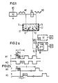
- An ink writing device (not shown here) contains a writing head which can be moved along a recording medium and which is fed via a supply line from an ink storage container TB shown in FIG. 1, the ink storage container TB containing three electrodes E1, E2, E3.
- the construction of such a storage container TB and the arrangement of the electrodes E1, E2, E3 can be carried out in the manner known from DE-PS 27 28 283.
- the electrodes E1, E2, E3 arranged in the bottom of the storage container TB serve to determine the supply of writing fluid TI in the storage container TB.
- the resistance of the writing fluid TI between the electrodes E2 and E3 changes with the temperature and the composition of the writing fluid TI in the same way as the measuring resistance measured between the electrodes E1 and E2.
- the resistance between the electrodes E1 and E2 is approximately equal to the resistance between the electrodes E2 and E3. If the liquid level drops, both resistances increase. However, the increase in the resistance value is initially only slight and the voltage U2 at the electrode E2 also changes only slightly at first. Only when the Ink level, the conductive ink cross-section between the electrodes E1 and E2 is greatly narrowed by the intermediate web ST. The resistance between the electrodes E1 and E2 therefore increases more than the resistance between the electrodes E2 and E3, so that the voltage U2 at the electrode E2 changes.
- the signal M1 is inverted via an inverter D3 and fed to the electrode E3 as a compensation signal M3.
- the mean time value of the voltage at the electrodes becomes zero.
- the signal M1 is at a "high” level and the compensation signal M3 is at a "low” level.
- the voltage U2 present at the electrode E2 which depends on the degree of filling of the storage container TB, is compared with a comparator voltage UV, which is derived from a supply voltage UCC using a voltage divider R1, R3, using a comparator KP contained in the control electronics ES. compared.
- the voltage U2 at the electrode E2 is greater than the reference voltage UV.
- the output voltage of the comparator thus leads to a "high" level and a downstream shutdown device AV remains inactive.
- the output voltage of the comparator leads to a "low" level, which triggers the shutdown device AV leads, which signals, for example optically and / or acoustically, the end of the ink supply and prevents printing characters from being output during continued writing operation.
- both an ink end and the ink end can be displayed. Since the voltage U2 applied to the electrode E2, that is to say the measured value, is subject to fluctuations both in static (stationary ink reservoir TB) and in dynamic (moving ink reservoir TB during writing operation), the end-of-ink detection has a certain degree of uncertainty.
- the typical voltage difference A U2 between the voltage measured for a full ink reservoir TB and the voltage for an empty reservoir TB is of the order of approximately 270 mV.
- the dynamic fluctuations in the measured value during the carriage movement can be more than 800 mV (typical).
- the measured value can fluctuate between “full” and “empty”.
- averaging of several measurements is carried out.
- a number of n queries (output signals of the comparator KP) are stored in the control electronics ES. If, for n queries, a number msn / 2 corresponds to the measured value "low” level, "ink end” is used for the evaluation; for a number of measured values m> n / 2 that result in "high” level, "ink” is available " rated.
- the voltage U2 can also be evaluated by an analog-digital converter AD of the control electronics SE for the writing device (broken line in FIG. 1).
- the n measured values for the voltage U2 are stored digitally in the control electronics ES after the A / D conversion.
- the end of ink query is carried out by measuring the voltage U2 during all possible operating states of the writing device.
- Measured values are queried both after the initialization, after a change of the storage container TB, in standby mode, before the start of writing, and during the writing operation. During the writing, the measurement must be carried out at a point in time at which it is only marginally influenced by dynamic fluctuations in the measured value U2 and / or by crosstalk of drive pulses for the writing mechanism. This measurement is therefore carried out after the last column of a row has been written and the mean value is formed according to the above-mentioned method.
- the possible query period AZ is shown hatched in FIG. 2 a) for the measurement signal M1.
- the measurement signal M1 carries "high" potential for the duration TM, while the compensation signal M3 carries "low” potential.
- the pulse-pause ratio of both pulses is 1. After a certain settling time TE, the measured value is stable and can be queried.
- the two pulses M1, M3 have the same duration TM, TK and the same amplitudes, so that the time average over a period is zero.
- the port output of the square-wave generator RG or the inverter D3 can have different residual voltages, which differs in slightly different amplitudes of the signals M1, M3 and thus one from zero
- the potential affects the electrodes the duration TM, TK of the pulses M1, M3 is limited to a short value, for example 100 lis.
- the compensation pulse M3 is only applied to the electrode E3 after a certain period of time T3 after the measuring pulse M1.
- the pulses M1, M3 have opposite signs and the time average over a period T is zero.
- the period T of the DC voltage pulses during write operation corresponds to the time for printing a line.
Landscapes
- Physics & Mathematics (AREA)
- General Physics & Mathematics (AREA)
- Engineering & Computer Science (AREA)
- Automation & Control Theory (AREA)
- Ink Jet (AREA)
- Measurement Of Levels Of Liquids Or Fluent Solid Materials (AREA)
- Impression-Transfer Materials And Handling Thereof (AREA)
Claims (13)
Applications Claiming Priority (2)
| Application Number | Priority Date | Filing Date | Title |
|---|---|---|---|
| DE3603333 | 1986-02-04 | ||
| DE3603333 | 1986-02-04 |
Publications (2)
| Publication Number | Publication Date |
|---|---|
| EP0244559A1 EP0244559A1 (fr) | 1987-11-11 |
| EP0244559B1 true EP0244559B1 (fr) | 1989-10-11 |
Family
ID=6293314
Family Applications (1)
| Application Number | Title | Priority Date | Filing Date |
|---|---|---|---|
| EP87101364A Expired EP0244559B1 (fr) | 1986-02-04 | 1987-02-02 | Dispositif de contrôle du stock d'encre dans des machines à écrire à encre |
Country Status (5)
| Country | Link |
|---|---|
| US (1) | US4788861A (fr) |
| EP (1) | EP0244559B1 (fr) |
| JP (1) | JPH0827206B2 (fr) |
| DE (1) | DE3760771D1 (fr) |
| ES (1) | ES2010675B3 (fr) |
Cited By (1)
| Publication number | Priority date | Publication date | Assignee | Title |
|---|---|---|---|---|
| DE4203294A1 (de) * | 1992-01-31 | 1993-08-05 | Mannesmann Ag | Verfahren und anordnung zur betriebszustandsueberwachung von tintendruckkoepfen |
Families Citing this family (31)
| Publication number | Priority date | Publication date | Assignee | Title |
|---|---|---|---|---|
| US5068806A (en) * | 1988-12-02 | 1991-11-26 | Spectra-Physics, Inc. | Method of determining useful life of cartridge for an ink jet printer |
| US5247609A (en) * | 1988-12-08 | 1993-09-21 | Thermo Separation Products (California) Inc. | Line density control for plotters |
| EP0374762B1 (fr) * | 1988-12-16 | 1995-03-15 | Canon Kabushiki Kaisha | Appareil d'enregistrement avec tête d'enregistrement amovible |
| JPH02165963A (ja) * | 1988-12-20 | 1990-06-26 | Canon Inc | 液体墳射記録装置 |
| JP2798948B2 (ja) * | 1989-01-28 | 1998-09-17 | キヤノン株式会社 | インクジェット記録装置 |
| US5162817A (en) * | 1989-01-28 | 1992-11-10 | Canon Kabushiki Kaisha | Ink jet with residual ink detection that compensates for different ink properties |
| EP0672528B1 (fr) * | 1989-01-28 | 2000-04-26 | Canon Kabushiki Kaisha | Tête à jet d'encre, réservoir d'encre et appareil à jet d'encre |
| JP2721009B2 (ja) * | 1989-04-28 | 1998-03-04 | キヤノン株式会社 | インクジェット記録装置 |
| JP3016393B2 (ja) * | 1989-06-29 | 2000-03-06 | キヤノン株式会社 | インクジェット記録装置 |
| DE69032780T2 (de) * | 1989-08-05 | 1999-06-02 | Canon K.K., Tokio/Tokyo | Tintenstrahlaufzeichnungsgerät und Tintenkassette dafür |
| US5070346A (en) * | 1990-01-30 | 1991-12-03 | Seiko Epson Corporation | Ink near-end detecting device |
| US5255019A (en) * | 1990-01-30 | 1993-10-19 | Seiko Epson Corporation | Ink near-end detecting device |
| US5844578A (en) * | 1990-01-30 | 1998-12-01 | Seiko Epson Corporation | Ink-jet recording apparatus and ink tank cartridge thereof |
| DE4007591A1 (de) * | 1990-03-09 | 1991-09-12 | Siemens Ag | Vorrichtung zur tintenvorratsueberwachung in tintenschreibeinrichtungen |
| US5136305A (en) * | 1990-12-06 | 1992-08-04 | Xerox Corporation | Ink jet printer with ink supply monitoring means |
| US6286921B1 (en) * | 1993-04-06 | 2001-09-11 | Sharp Kabushiki Kaisha | Ink cartridge of an ink jet printer and an ink jet printer including an ink cartridge |
| JP3219641B2 (ja) * | 1994-07-15 | 2001-10-15 | キヤノン株式会社 | インクジェット記録装置およびインクの残量低下の判別方法ならびに情報処理装置 |
| FR2743749B1 (fr) * | 1996-01-22 | 1998-04-10 | Canon Kk | Procede et dispositif de determination de la repartition de produit present dans un reservoir, notamment d'encre dans un dispositif de transfert d'image |
| EP0873243A1 (fr) * | 1996-01-22 | 1998-10-28 | Canon Kabushiki Kaisha | Procede et dispositif pour determiner la quantite de produit dans un reservoir, et en particulier, la quantite d'encre dans un dispositif de formation d'images |
| US6106087A (en) * | 1996-10-01 | 2000-08-22 | Brother Kogyo Kabushiki Kaisha | Detection apparatus for detecting residual ink quantity in ink cartridge |
| JP3423166B2 (ja) * | 1996-10-18 | 2003-07-07 | ブラザー工業株式会社 | インク有無検知装置およびインクジェット記録装置 |
| FR2765335B1 (fr) * | 1997-06-27 | 1999-10-01 | Canon Kk | Procede et dispositif de suivi de consommation d'un produit tel qu'une encre, contenu dans un reservoir |
| FR2765334B1 (fr) * | 1997-06-27 | 1999-10-01 | Canon Kk | Procede et dispositif de controle de l'etat operationnel d'un reservoir, par exemple un reservoir d'encre |
| US6539286B1 (en) * | 1998-01-26 | 2003-03-25 | Micron Technology, Inc. | Fluid level sensor |
| CN1370298A (zh) * | 1999-05-20 | 2002-09-18 | 岚瑟股份有限公司 | 带有电子控制系统的饮料配售机 |
| US20020108439A1 (en) * | 2001-02-14 | 2002-08-15 | Whitehead Dennis D. | Systems and methods for displaying status of consumable resource |
| US6626513B2 (en) | 2001-07-18 | 2003-09-30 | Lexmark International, Inc. | Ink detection circuit and sensor for an ink jet printer |
| JP4742683B2 (ja) * | 2005-06-02 | 2011-08-10 | ソニー株式会社 | 液体検知装置及び液体吐出装置 |
| JP2010197238A (ja) * | 2009-02-25 | 2010-09-09 | Sumitomo Rubber Ind Ltd | 回転速度情報検出装置、方法及びプログラム、並びに、タイヤ空気圧低下検出装置、方法及びプログラム |
| EP3631209A1 (fr) * | 2017-05-24 | 2020-04-08 | Bilge Sense Llc | Commutateur de détection de liquide |
| JP2021139815A (ja) * | 2020-03-06 | 2021-09-16 | オムロン株式会社 | 液体検出装置および液体検出方法 |
Family Cites Families (11)
| Publication number | Priority date | Publication date | Assignee | Title |
|---|---|---|---|---|
| DE2438273A1 (de) * | 1974-08-08 | 1976-02-19 | Teldix Gmbh | Verfahren zur umwandlung eines digitalen messwerts und anordnung hierzu |
| DE2728283C2 (de) * | 1977-06-23 | 1982-04-29 | Siemens AG, 1000 Berlin und 8000 München | Vorrichtung zur Überwachung des Tintenvorrates in Tintenschreibeinrichtungen |
| DE2835413A1 (de) * | 1978-08-12 | 1980-02-21 | Hoechst Ag | Einrichtung zur elektrischen standueberwachung einer entwicklerloesung in einem vorratsgefaess |
| GB2072851A (en) * | 1980-03-12 | 1981-10-07 | In Place Cleaning Ltd | Liquid level detector circuits |
| US4470296A (en) * | 1981-12-28 | 1984-09-11 | Nissan Motor Company, Limited | Fuel gauge for an automotive vehicle |
| US4590413A (en) * | 1982-01-11 | 1986-05-20 | Eaton Corporation | EV drivetrain inverter with V/HZ optimization |
| DE3322825A1 (de) * | 1983-06-24 | 1985-01-03 | Siemens AG, 1000 Berlin und 8000 München | Schaltungsanordnung zur pegelueberwachung elektrisch leitfaehiger fluessigkeiten |
| US4550261A (en) * | 1983-09-19 | 1985-10-29 | Chrysler Corporation | Fluid level sensor circuitry |
| JPS60137661A (ja) * | 1983-12-26 | 1985-07-22 | Canon Inc | 液体貯留装置 |
| DE3425212A1 (de) * | 1984-07-09 | 1986-01-16 | Vdo Adolf Schindling Ag, 6000 Frankfurt | Fuellstandsanzeige |
| US4602344A (en) * | 1984-10-25 | 1986-07-22 | Air Products And Chemicals, Inc. | Method and system for measurement of liquid level in a tank |
-
1987
- 1987-01-30 US US07/008,756 patent/US4788861A/en not_active Expired - Lifetime
- 1987-02-02 ES ES87101364T patent/ES2010675B3/es not_active Expired
- 1987-02-02 EP EP87101364A patent/EP0244559B1/fr not_active Expired
- 1987-02-02 DE DE8787101364T patent/DE3760771D1/de not_active Expired
- 1987-02-04 JP JP62022644A patent/JPH0827206B2/ja not_active Expired - Lifetime
Cited By (1)
| Publication number | Priority date | Publication date | Assignee | Title |
|---|---|---|---|---|
| DE4203294A1 (de) * | 1992-01-31 | 1993-08-05 | Mannesmann Ag | Verfahren und anordnung zur betriebszustandsueberwachung von tintendruckkoepfen |
Also Published As
| Publication number | Publication date |
|---|---|
| DE3760771D1 (en) | 1989-11-16 |
| JPS62190421A (ja) | 1987-08-20 |
| JPH0827206B2 (ja) | 1996-03-21 |
| EP0244559A1 (fr) | 1987-11-11 |
| ES2010675B3 (es) | 1989-12-01 |
| US4788861A (en) | 1988-12-06 |
Similar Documents
| Publication | Publication Date | Title |
|---|---|---|
| EP0244559B1 (fr) | Dispositif de contrôle du stock d'encre dans des machines à écrire à encre | |
| DE2728283A1 (de) | Vorrichtung zur ueberwachung des tintenvorrates in tintenschreibeinrichtungen | |
| DE2740289C3 (de) | Vorrichtung zur Überwachung des Niveaus einer in einem Behälter enthaltenen Flüssigkeit | |
| DE3036347C2 (fr) | ||
| DE3237396C2 (fr) | ||
| DE2346558C2 (de) | Regelkreis für die Geschwindigkeitskonstanthaltung der Tintentropfen eines Tintenstrahldruckers | |
| EP0139874B1 (fr) | Circuit pour la mesure thermoélectrique du niveau de remplissage | |
| DE3028738A1 (de) | Verfahren und vorrichtung zum messen eines kraftstoff-vorrates in einem tank | |
| DE2711529A1 (de) | Verfahren und vorrichtung fuer die stroemungskompensierte amperometrische messung einer stroemung | |
| DE3423802A1 (de) | Verfahren und einrichtung zur elektrothermischen, umgebungstemperatur-kompensierten fuellstandsmessung | |
| DE3408824A1 (de) | Schaltungsanordnung zur elektrothermischen, umgebungstemperatur-kompensierten fuellstandsmessung | |
| EP0377599B1 (fr) | Installation d'impression a tete d'impression comandee electrothermiquement | |
| DE4318891A1 (de) | Elektrochemisches Gasspurenmeßsystem mit Funktionskontrolle | |
| DE69611411T2 (de) | Verfahren und System zur Überwachung des Tonergehalts eines Tintenstrahldruckkopfes | |
| EP0898368B1 (fr) | Dispositif capteur | |
| DE2412852C3 (de) | Anordnung zum Erkennen der Tröpfchenfrequenz und des Ablösezeitpunktes einzelner Tröpfchen in Tintenstrahlschreiber!! | |
| DE3917935A1 (de) | Vorrichtung und verfahren zur bestimmung der waermeleitfaehigkeit und konzentration von fluessigkeitsgemischen | |
| DE102008028320B4 (de) | Flüssigkeitspegel-Erfassungsvorrichtung | |
| DE3644095A1 (de) | Messvorrichtung fuer die resttinte in einem flexiblen tintensack in tintenschreibeinrichtungen | |
| DE69228526T2 (de) | Verfahren zur Messung des Ladezustandes eines elektrochemischen Generators | |
| DE69413297T2 (de) | Verbesserungen an Flüssigkeitsstandsmessern mit Widerstandsdraht | |
| DE2723809A1 (de) | Verfahren zur messung von stroemungsgeschwindigkeiten | |
| DE3113066C2 (de) | Tintenüberwachungseinrichtung für Tintenstrahlschreiber | |
| DE3002668A1 (de) | Einrichtung zur analogen messung einer groesse mit fernanzeige | |
| DE69404521T2 (de) | Vorrichtung zur Messung des Niveaus und/oder des Volumens einer Flüssigkeit mit einem Tauchwiderstandsdraht |
Legal Events
| Date | Code | Title | Description |
|---|---|---|---|
| PUAI | Public reference made under article 153(3) epc to a published international application that has entered the european phase |
Free format text: ORIGINAL CODE: 0009012 |
|
| AK | Designated contracting states |
Kind code of ref document: A1 Designated state(s): CH DE ES FR GB IT LI NL SE |
|
| 17P | Request for examination filed |
Effective date: 19880125 |
|
| 17Q | First examination report despatched |
Effective date: 19890315 |
|
| GRAA | (expected) grant |
Free format text: ORIGINAL CODE: 0009210 |
|
| AK | Designated contracting states |
Kind code of ref document: B1 Designated state(s): CH DE ES FR GB IT LI NL SE |
|
| REF | Corresponds to: |
Ref document number: 3760771 Country of ref document: DE Date of ref document: 19891116 |
|
| ET | Fr: translation filed | ||
| ITF | It: translation for a ep patent filed | ||
| GBT | Gb: translation of ep patent filed (gb section 77(6)(a)/1977) | ||
| PLBE | No opposition filed within time limit |
Free format text: ORIGINAL CODE: 0009261 |
|
| STAA | Information on the status of an ep patent application or granted ep patent |
Free format text: STATUS: NO OPPOSITION FILED WITHIN TIME LIMIT |
|
| 26N | No opposition filed | ||
| PGFP | Annual fee paid to national office [announced via postgrant information from national office to epo] |
Ref country code: GB Payment date: 19910118 Year of fee payment: 5 |
|
| PGFP | Annual fee paid to national office [announced via postgrant information from national office to epo] |
Ref country code: FR Payment date: 19910219 Year of fee payment: 5 Ref country code: ES Payment date: 19910219 Year of fee payment: 5 |
|
| PGFP | Annual fee paid to national office [announced via postgrant information from national office to epo] |
Ref country code: SE Payment date: 19910222 Year of fee payment: 5 |
|
| ITTA | It: last paid annual fee | ||
| PGFP | Annual fee paid to national office [announced via postgrant information from national office to epo] |
Ref country code: NL Payment date: 19910228 Year of fee payment: 5 |
|
| PGFP | Annual fee paid to national office [announced via postgrant information from national office to epo] |
Ref country code: CH Payment date: 19910524 Year of fee payment: 5 |
|
| PG25 | Lapsed in a contracting state [announced via postgrant information from national office to epo] |
Ref country code: GB Effective date: 19920202 |
|
| PG25 | Lapsed in a contracting state [announced via postgrant information from national office to epo] |
Ref country code: SE Effective date: 19920203 Ref country code: ES Free format text: LAPSE BECAUSE OF NON-PAYMENT OF DUE FEES Effective date: 19920203 |
|
| PG25 | Lapsed in a contracting state [announced via postgrant information from national office to epo] |
Ref country code: LI Effective date: 19920229 Ref country code: CH Effective date: 19920229 |
|
| PG25 | Lapsed in a contracting state [announced via postgrant information from national office to epo] |
Ref country code: NL Effective date: 19920901 |
|
| GBPC | Gb: european patent ceased through non-payment of renewal fee | ||
| NLV4 | Nl: lapsed or anulled due to non-payment of the annual fee | ||
| PG25 | Lapsed in a contracting state [announced via postgrant information from national office to epo] |
Ref country code: FR Effective date: 19921030 |
|
| REG | Reference to a national code |
Ref country code: CH Ref legal event code: PL |
|
| REG | Reference to a national code |
Ref country code: FR Ref legal event code: ST |
|
| EUG | Se: european patent has lapsed |
Ref document number: 87101364.5 Effective date: 19920904 |
|
| REG | Reference to a national code |
Ref country code: ES Ref legal event code: FD2A Effective date: 19990201 |
|
| PGFP | Annual fee paid to national office [announced via postgrant information from national office to epo] |
Ref country code: DE Payment date: 19991229 Year of fee payment: 14 |
|
| PG25 | Lapsed in a contracting state [announced via postgrant information from national office to epo] |
Ref country code: DE Free format text: LAPSE BECAUSE OF NON-PAYMENT OF DUE FEES Effective date: 20011201 |
|
| PG25 | Lapsed in a contracting state [announced via postgrant information from national office to epo] |
Ref country code: IT Free format text: LAPSE BECAUSE OF NON-PAYMENT OF DUE FEES Effective date: 20050202 |