EP0244228B1 - Drucker für einfarbiges und mehrfarbiges Drucken - Google Patents
Drucker für einfarbiges und mehrfarbiges Drucken Download PDFInfo
- Publication number
- EP0244228B1 EP0244228B1 EP87303816A EP87303816A EP0244228B1 EP 0244228 B1 EP0244228 B1 EP 0244228B1 EP 87303816 A EP87303816 A EP 87303816A EP 87303816 A EP87303816 A EP 87303816A EP 0244228 B1 EP0244228 B1 EP 0244228B1
- Authority
- EP
- European Patent Office
- Prior art keywords
- ink ribbon
- printer
- colour
- monochromatic
- ribbon cartridge
- Prior art date
- Legal status (The legal status is an assumption and is not a legal conclusion. Google has not performed a legal analysis and makes no representation as to the accuracy of the status listed.)
- Expired - Lifetime
Links
Images


Classifications
-
- B—PERFORMING OPERATIONS; TRANSPORTING
- B41—PRINTING; LINING MACHINES; TYPEWRITERS; STAMPS
- B41J—TYPEWRITERS; SELECTIVE PRINTING MECHANISMS, i.e. MECHANISMS PRINTING OTHERWISE THAN FROM A FORME; CORRECTION OF TYPOGRAPHICAL ERRORS
- B41J35/00—Other apparatus or arrangements associated with, or incorporated in, ink-ribbon mechanisms
- B41J35/16—Multicolour arrangements
- B41J35/18—Colour change effected automatically
-
- B—PERFORMING OPERATIONS; TRANSPORTING
- B41—PRINTING; LINING MACHINES; TYPEWRITERS; STAMPS
- B41J—TYPEWRITERS; SELECTIVE PRINTING MECHANISMS, i.e. MECHANISMS PRINTING OTHERWISE THAN FROM A FORME; CORRECTION OF TYPOGRAPHICAL ERRORS
- B41J33/00—Apparatus or arrangements for feeding ink ribbons or like character-size impression-transfer material
- B41J33/14—Ribbon-feed devices or mechanisms
- B41J33/54—Ribbon-feed devices or mechanisms for ensuring maximum life of the ribbon
- B41J33/56—Ribbon adjusted transversely
-
- B—PERFORMING OPERATIONS; TRANSPORTING
- B41—PRINTING; LINING MACHINES; TYPEWRITERS; STAMPS
- B41J—TYPEWRITERS; SELECTIVE PRINTING MECHANISMS, i.e. MECHANISMS PRINTING OTHERWISE THAN FROM A FORME; CORRECTION OF TYPOGRAPHICAL ERRORS
- B41J2/00—Typewriters or selective printing mechanisms characterised by the printing or marking process for which they are designed
- B41J2/005—Typewriters or selective printing mechanisms characterised by the printing or marking process for which they are designed characterised by bringing liquid or particles selectively into contact with a printing material
- B41J2/01—Ink jet
- B41J2/015—Ink jet characterised by the jet generation process
- B41J2/02—Ink jet characterised by the jet generation process generating a continuous ink jet
- B41J2/03—Ink jet characterised by the jet generation process generating a continuous ink jet by pressure
-
- B—PERFORMING OPERATIONS; TRANSPORTING
- B41—PRINTING; LINING MACHINES; TYPEWRITERS; STAMPS
- B41J—TYPEWRITERS; SELECTIVE PRINTING MECHANISMS, i.e. MECHANISMS PRINTING OTHERWISE THAN FROM A FORME; CORRECTION OF TYPOGRAPHICAL ERRORS
- B41J35/00—Other apparatus or arrangements associated with, or incorporated in, ink-ribbon mechanisms
- B41J35/04—Ink-ribbon guides
- B41J35/10—Vibrator mechanisms; Driving gear therefor
- B41J35/12—Vibrator mechanisms; Driving gear therefor adjustable, e.g. for case shift
- B41J35/14—Vibrator mechanisms; Driving gear therefor adjustable, e.g. for case shift for multicolour work; for ensuring maximum life of ink ribbon; for rendering ink-ribbon inoperative
-
- B—PERFORMING OPERATIONS; TRANSPORTING
- B41—PRINTING; LINING MACHINES; TYPEWRITERS; STAMPS
- B41J—TYPEWRITERS; SELECTIVE PRINTING MECHANISMS, i.e. MECHANISMS PRINTING OTHERWISE THAN FROM A FORME; CORRECTION OF TYPOGRAPHICAL ERRORS
- B41J35/00—Other apparatus or arrangements associated with, or incorporated in, ink-ribbon mechanisms
- B41J35/22—Mechanisms permitting the selective use of a plurality of ink ribbons
Definitions
- the present invention relates to a printer for monochromatic and multi-colour printing.
- Monochromatic printers have previously been used only for monochromatic printing. In such printers it has not been possible to effect colour printing, while in multi-colour printers, it has not been possible to effect monochromatic printing even if a monochromatic ink ribbon cartridge is loaded into the printer. Thus, printers have generally been either for monrochromatic or for colour printing only.
- a printer comprising a printing head; a cartridge holder for releasably holding a multi-colour ink ribbon cartridge containing ink ribbon material different parts of which are differently coloured; and drive means for adjusting, by way of drive transmission means, the relative positions of the printing head and of a multi-colour ink ribbon cartridge held in the cartridge holder to enable a selected said part of the ink ribbon material and the printing head to be brought into alignment for printing characterised in that the cartridge holder is also adapted releasably to hold a cartridge containing a monochromatic ink ribbon, the drive means being freely removable from the printer, the arrangement being such that, when the drive means is removed from the printer, only monochromatic printing can be effected and, when the drive means is installed on the printer, either multi-coloured or monochromatic printing can be effected as desired.
- the cartridge holder may be arranged to be pivotally rotated by a drive transmission means so as to bring a selected said part into alignment with the printing head.
- the cartridge holder is preferably pivotally mounted in a carriage which carries the printing head and the drive transmission means.
- the drive transmission means may comprise a transmission gear which is rotatably mounted in the carriage and meshes with a gear on the drive means when the latter is also mounted in the carriage, rotation of the transmission gear effecting pivotal movement of the cartridge holder by way of an oscillatable lever.
- the last-mentioned means may comprise a pair of contacts whose open or closed state is arranged to be altered by a projection on a multi-coloured ink ribbon cartridge.
- the last-mentioned means may comprise a pair of contacts whose open or closed state is arranged to be altered by a projection on the carriage.
- the drive means may be controlled by a control circuit which is adjustable by means of a variable resistor.
- the cartridge holder may be provided with means for providing a multi-colour ink ribbon cartridge with a pivotal mounting, the drive transmission means comprising a thrust member which is moved by the drive means and is engageable with the multi-colour ink ribbon cartridge so as to effect pivotal movement of the latter.
- the drive transmission means may in this case comprise a cam having a profile which engages the thrust member.
- the drive means and the drive transmission means may be mounted in a common unit.
- Bayonet fixing means may be provided for securing the said common unit to a carriage of the printer.
- Figure 15 depicts a colour selecting mechanism of a prior multi-colour printer.
- a motor 81 for selecting colour is provided under a paper guide 88.
- the power supplied by the motor 81 is transmitted to a cam 82 and to an oscillatable lever 83.
- the oscillatable lever 83 vertically moves a cartridge holder 84 in which an ink ribbon cartridge 85 is mounted. Such vertical movement thus selects the position of a portion of a multi-coloured ribbon (or of one of a plurality of differently coloured ribbons 86) in the cartridge holder 84 with respect to a printing head (not shown) and consequently selects the colour to be printed on a sheet of paper (not shown) on a platen 87.
- the motor 81 is permanently secured to the printer body and neither the motor 81 itself, nor the driving unit consisting of the motor 81 and its peripherals (not shown), can be easily removed by an user.
- a detecting means or the like is to be additionally incorporated in a multi-colour printer in order that the user can use both a monochromatic ink ribbon cartridge and a multi-colour ink ribbon cartridge in the same printer, it is necessary to detect both what kind of ink ribbon cartridge has been selected and the home position of the ink ribbon cartridge. In this case, accordingly, two or more detectors would normally be required.
- the printer can easily detect whether a monochromatic ink ribbon cartridge or a multi-colour ink ribbon cartridge has been loaded, while a home positioning of the particular ink ribbon cartridge employed can be accurately performed by using a signal from only one switching means; and (c) fine adjustment of the upper and the lower positions of the ink ribbon cartridge can be accurately and easily performed.
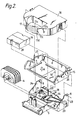
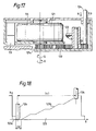
- Figure 1 is a plan view of a first embodiment of a printer in accordance with the present invention.
- Figure 1 there is shown a printer having a carriage 5 which is slidably mounted for oscillation on guide shafts 2, 3 which are parallel to a platen 1.
- the printer has a printing head 4 secured to the carriage 5 and a transmission gear 13 and an oscillatable lever 14, which form part of a power transmission mechanism, are engaged with each other and are axially supported separately on the carriage 5.
- An arm 16 of the ink ribbon cartridge holder 15 is adapted to engage with a joint portion 28 of the oscillatable lever 14.
- the carriage 5 is provided with claws 21, 22 for securing a colour-selecting motor unit 19.
- the carriage 5 is also provided with a connector 25 for electrically connecting an electric circuit to the motor unit 19.
- the motor unit 19 When multi-colour printing is selected the motor unit 19 is pushed down in the direction shown by an arrow A and is attached to the carriage 5. With the motor unit 19 mounted in position on the carriage, a gear 20 protruding from the motor unit 19 engages with inner teeth 30 ( Figures 3-5) of the transmission gear 13, thereby permitting the power of the motor unit 19 to be transmitted, as described below, to the ink ribbon cartridge holder 15 as well as connecting the motor unit 19 to the connector 25 and consequently to the electric circuit.
- the transmission gear 13 is provided with the inner teeth 30 and with another group of teeth 31 which are formed integrally around a centre shaft hole 32.
- a stub shaft 5 b ( Figure 6) carried by the carriage 5 is mounted in the hole 32 so that the transmission gear 13 is rotatably mounted on and carried by the carriage 5, the transmission gear being mounted on a shoulder portion of the stub shaft 5 b .
- the oscillatable lever 14, as shown in Figure 3 has a bush 29 at one end thereof provided with a through hole 29 a .
- a stub shaft 5 a ( Figure 6) carried by the carriage 5 is mounted in the hole 29 a .
- the oscillatable lever 14 is thus supported by the carriage 5 and is rotatable about the fulcrum provided by the stub shaft 5 a .
- the lower surface of the bush 29 is supported by the upper surface of the carriage 5, the upper surface of the bush 29 supporting the lower surface of the cartridge holder 15.
- the oscillatable lever 14 has inner teeth 33 (Figure 5) which engage with the teeth 31 of the transmission gear 13. The lower surfaces of the inner teeth 33 contact the shoulder portion of the stub shaft 5 b .
- the motor unit 19 When pushed into the predetermined position, the motor unit 19 is secured by the claws 21 and 22.
- a colour switching operation of an ink ribbon 17 is described below, the ink ribbon 17 having a plurality of differently coloured bands 17 a , 17 b , 17 c , 17 d ( Figure 2).
- the ink ribbon colour is selected by using the rotation of the motor 19 which moves the oscillatable lever 14 in the direction shown by the arrow B or by the arrow D and consequently by rotating the ink ribbon cartridge holder 15 in the direction shown by the arrow C or by the arrow E.
- monochromatic printing or multi-colour printing can be selected at will and either a monochromatic or a multi-colour ink ribbon cartridge can be used in the same printer.
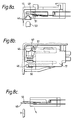
- the printer is provided with an ink ribbon cartridge detector 47 and with a cartridge home position detecting mechanism which are described below with reference to Figures 6 to 9.
- the carriage 5 On opposite sides of the carriage 5 are the holes 8 for supporting the projections 26,27 on the opposite sides of the ink ribbon cartridge holder 15.
- the ink ribbon cartridge holder 15 is oscillatable around the projections 26,27.
- the carriage 5 is provided with a projection 9 for establishing a colour home position of the cartridge holder 15.
- Figure 7 shows the construction of the detector 47.
- the detector 47 is formed of detecting members 40, 41 and 42, contact plates 43 and 44 of conductive material secured between the detecting members 41, 42 and 40, 41 respectively, and an actuator 46 which is rotatably mounted on a portion 45 of the detecting member 40.
- the detector 47 is secured on the cartridge holder 15 by means of claws provided at the lower portion of the detecting member 42.
- the contact plates 43 and 44 have wings 48, 49 and 50, 51, respectively.
- the wings 48 and 50 are normally open circuited and the wings 49 and 51 are normally closed circuited, thus forming a two-contact one-circuit switch.
- the colour ribbon such as the ribbon 17, is divided into four strips 17 a , 17 b , 17 c , 17 d of B (black), M (magenta), C (cyan) and Y (yellow), the strips 17 a - 17 d extending longitudinally of the ribbon 17, and the width of the ribbon being about 1 inch (2.54 cms).
- a monochromatic ink ribbon (not shown) is about 13mm in width. Accordingly, the thickness of the ribbon cartridge which has been used in a printer has depended upon whether it is for a multi-colour ink ribbon or for a monochromatic ink ribbon. As a result, when ribbon cartridge cases of different thicknesses are loaded into the same printer, if the initial ribbon home positioning operation of the printer is fixed, the printing is not always carried out on the central portion of the colour section of the ink ribbon.
- a projection 53 is provided, as shown in Figure 9, on the bottom of the multi-colour ink ribbon cartridge 18 for pushing down the actuator 46.
- the lower portion of the actuator 46 engages with the wing portion 49 of the contract plate 43 and so, when the actuator 46 is pushed down, the normally closed contact plates 49 and 51 are opened.
- the contact plates 49 and 51 are open, and when a monochromatic ink ribbon is loaded, the contact plates 49 and 51 are closed.
- the contact plates 49, 51 serve to detect whether a multi-colour or a monochromatic ink ribbon is being used.
- the other contact plates 48 and 50 which are provided for detecting the colour home positioning, are normally open.
- the power from the motor unit 19 mounted in the carriage 5 is transmitted to the ink ribbon cartridge holder 15 by the transmission mechanism 13, 14 and consequently the ink ribbon cartridge holder 15 is rotated in the downward direction.
- the colour home position projection 9 provided on the carriage 5 presses and closes the contact plates 48 and 50.
- the rotation of the motor unit 19 is decelerated and stopped.
- the position of the ink ribbon cartridge holder 15 at this time is called the "colour home position".
- the cartridge holder 15 is rotated in the upward direction to open the contact plates 48 and 50.
- a signal A ⁇ in Figure 10 is read. If the signal A ⁇ indicates that the contact plates 48, 50 are "closed", the loaded ribbon is detected to be a monochromatic ink ribbon and the cartridge holder 15 moves to a suitable position such that the printing head 4 strikes the center of the total width of the monochromatic ink ribbon and stays at this position.
- the loaded ribbon is detected to be a multi-colour ink ribbon and the cartridge holder 15 is rotated in the downward direction until the contact plates 48 and 50 close and is moved to a suitable position such that the printing head 4 strikes the centre of the total width of the multi-colour ink ribbon and stays at this position.
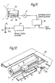
- FIG. 11 and 12 A method for adjusting the optimum position of an ink ribbon cartridge with respect to a printing head of a second embodiment of a printer according to the present invention is now described with reference to Figures 11 and 12.
- the printer of Figures 11 and 12 is generally similar to that described above, like reference numerals indicating like parts.
- the carriage 5 holds the printing head 4 which is responsive to a printing signal delivered from an host device (not shown in the drawings) for printing information on paper or other record medium (not shown) mounted on the platen 1.
- the carriage 5 further includes an ink ribbon cartridge holder 63 which is in contact with a power transmitting means consisting of a driving means 61, such as a stepping motor M, and an eccentric cam 62 driven by the driving means 61.
- the ink ribbon cartridge holder 63 moves the ink ribbon surface with respect to the printing head 4.
- a semi-fixed variable resistor 67 is provided on a portion of the printer body 68 ( Figure 12) accessible to instruments or tools which can be easily inserted from outside the printer body 68.
- the variable resistor 67 receives a reference voltage VS and outputs, from a sliding terminal 67 b , a voltage corresponding to the angular setting of an adjusting knob 67 a .
- An analog-digital converter 69 is provided for converting the analog value of the voltage delivered from the semi-fixed variable resistor 67 into a digital signal.
- An ink ribbon colour selecting circuit 70 in response to a printing colour designating signal from the external host device or from an operational board (not shown) of the printer body 68, actuates the driving means 61 and controls the relative height of the ink ribbon and the printing head 4. Moreover, the colour selecting circuit 70 is further constructed to that the initial position is altered only by an amount which corresponds to the signal fed to it by the analog-digital converter 69.
- the ink ribbon colour selecting circuit 70 when the power switch (not shown) of the printer is turned on, the ink ribbon colour selecting circuit 70 is actuated to rotate the driving means 61 by an amount corresponding to the signal delivered to the ink ribbon colour selecting circuit 70 from the analog-digital converter 69, i.e. by an amount preset by the semi-fixed variable resistor 67, thereby adjusting the initial position of the ink ribbon cartridge 18.
- the ink ribbon colour selecting circuit 70 actuates the driving means 61 according to the printing colour designating signal to move the printing head side of the ink ribbon cartridge 18 until the section of its ink ribbon having the designated colour faces the printing head 4, the cartridge 18, then being maintained at that position.
- the carriage 5 moves in the printing direction and the printing head 4 prints the patterns corresponding to the printing data on the paper or other record medium using the selected colour section of the ink ribbon.
- the position is adjusted in the following way.
- the host device or the operation board of the printer is operated to output a printing colour designating signal.
- a gauge is applied to the ink ribbon cartridge 18 to detect the relative positioning of the ink ribbon and the printing head 4.
- the adjusting knob 67 a of the semi-fixed resistor 67 is rotated with a screwdriver or other suitable tool. Then the semi-fixed variable resistor 67 outputs from the sliding terminal 67 b a voltage which depends upon the angular setting of the adjusting knob 67 a .
- the analog value of this voltage is converted into a digital signal by the analog-digital converter 69 and the digital signal is fed to the ink ribbon colour selecting circuit 70.
- the ink ribbon colour selecting circuit 70 outputs a signal corresponding to the digital-converted value of the voltage from the converter 69 to actuate the driving means 61 to move the ink ribbon cartridge holder 63.
- the ink ribbon cartridge 18 then moves vertically with respect to the printing head 4.
- the adjusting knob 67 a of the semi-fixed variable resistor 67 is slowly rotated until the selected colour section of the ink ribbon faces the printing head 4. Then the adjustment is completed and the gauge is removed.
- the adjustment effected by rotating the adjusting knob 67 a adjusts the effective resistance of the semi-fixed variable resistor 67.
- the new effective resistance is therefore maintained after the adjustment, and accordingly, is stored regardless of whether the power switch of the printer is turned on or off.
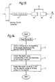
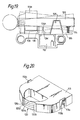
- Figure 13 illustrates the operation of the embodiment of Figures 11 and 12.
- the voltage output from the variable resistor 67 is converted from an analog to a digital value by the analog-digital converter 69 which in turn outputs a digital-converted signal to a register 71.
- the register 71 is, for instance, an 8-bit register
- the signal from the variable resistor 67 is converted to a value from 0 to 255 and fed into the register 71.
- the value stored in the register 71 is divided by n and the number of pulses is set within a pulse number setting register 72 corresponding to the quotient.
- the signal from the variable resistor 67 is divided by 10, for example, when the value stored in the register 71 is 0 to 19, the corresponding value 1 is set within the register 72, and when the value in the register 71 is 20 to 39, the corresponding value 2 is set within the register 72.
- a pulse 73 for driving the driving member (e.g. a stepping motor) 61 is inputted to a counter 74 which counts the number of pulses 73. Every time when a pulse 73 is inputted to the counter 74, the value in the counter 74 and the value in the register 72 are compared and, until the values coincide with each other, a pulse is inputted into the driving member 61 to rotate the driving member 61.
- a pulse 73 for driving the driving member (e.g. a stepping motor) 61 is inputted to a counter 74 which counts the number of pulses 73. Every time when a pulse 73 is inputted to the counter 74, the value in the counter 74 and the value in the register 72 are compared and, until the values coincide with each other, a pulse is inputted into the driving member 61 to rotate the driving member 61.
- Figure 14 is a flow chart illustrating the operation of setting the number of pulses in the register 72 after the power is turned on.
- step 1 When the power is turned on (step 1), a voltage corresponding to the resistance set by the variable resistor 67 is fed to the analog-digital converter (step 2) and then the digital value corresponding to this voltage is outputted to the output register 71 (step 3). Thereafter, the value set within the register 71 is divided by n and the desired number of driving pulses is calculated and set in the register 72 (step 4).
- the printer described above has the following advantages.
- the said third embodiment comprises a cartridge holder 115 which is mounted on or integral with a carriage 111.
- the cartridge holder 115 is arranged, as more fully described below, to carry a multi-colour ink ribbon cartridge 113.
- a spring 114 is interposed between the cartridge 113 and the cartridge holder 115 so as to bias the cartridge 113 towards a print head 112.
- the carriage 111 is provided with fixing pawls 117, 118 for fixing a motor unit 116 in a position in the carriage 111 in which it will be connected to a connector 119 which is itself connected to an electrical circuit (not shown).
- the motor unit 116 acts as a driving unit and may be introduced into its operative position by pushing it downwardly in the direction of an arrow K from a position above the carriage 111.
- the motor unit 116 When the motor unit 116 has been pushed into its operative position, it is supported by the fixing pawls 117 and 118, and at the same time, the motor unit 116 is connected to the connector 119 and is thus connected to the electrical circuit.
- the motor unit 116 may be freely removed from the printer merely by lifting the motor unit 116 upwardly after manually moving the ends of the fixing pawls 117, 118 away from each other.
- the motor unit 116 comprises a motor 121 which acts as the drive means for selecting one of a plurality of colours to be printed.
- the motor unit 116 also comprises a transmission gear 122, a cam 123, and a thrust member 124.
- the motor 121 has a motor gear 121 a which meshes with the transmission gear 122, the latter meshing with the cam 123.
- the parts 121 a , 122, 123, 124 constitute drive transmission means for imparting drive to the thrust member 124 so as to alter the relative positions of the print head 112 and cartridge 113.
- the multi-colour ink ribbon cartridge 113 holds a multi-colour ribbon 120 as best shown in Figure 20.
- the ribbon 120 is provided with a plurality of differently coloured bands 120 a , 120 b , 120 c , and 120 d .
- a resilient member 113 b having a stub shaft 113 a is provided at each of the opposite sides of the multi-colour ribbon cartridge 113 so that the stub shafts 113 a are urged outwardly with respect to the cartridge 113.
- a groove 113 c ( Figure 16) is provided in the lower surface of the multi-colour ribbon cartridge 113 as a clearance groove for receiving a positioning member 130 for a monochromatic ink ribbon cartridge 129 ( Figure 19).
- the multi-colour ink ribbon cartridge 113 When the multi-colour ink ribbon cartridge 113 is held in the cartridge holder 115, the multi-colour ink ribbon cartridge 113 is supported by the stub shafts 13 a which have been manually pressed towards each other and then introduced into holes 126 for receiving the shafts at the sides of the cartridge holder 115.
- the multi-coloured ink ribbon cartridge 113 is thus held with its multi-colour ribbon disposed adjacent to a platen 125.
- the multi-colour ink ribbon cartridge 113 is urged in the direction of an arrow L by the spring 114 connected to the cartridge holder 115.
- the thrust member 124 projects from the motor unit 116 and engages the lower surface of the multi-colour ink ribbon cartridge 113 for positioning the latter, the extent to which the thrust member 124 projects from the motor unit 116 determining which of the coloured bands 120 a , 120 b , 120 c , 120 d is disposed centrally of the platen 125 in a printing position.
- the thrust member 124 is moved along a slope 123 b ( Figure 18) of the cam 123 in the direction of an arrow P, whereby the multi-colour ink ribbon cartridge 113 is pivotally rotated in the direction of an arrow M.
- the multi-colour ink ribbon 120 is moved and stops at a position opposite to the print head 112 so that the desired colour band may be used.
- the rotation of the motor 21 is then stopped.
- the print head 112 is then driven so that the desired colour printing is effected on paper or other record medium.
- the multi-colour ink ribbon cartridge 113 may readily be released from the cartridge holder 115 merely by pressing the stub shafts 113 a towards each other so as to extract them from the holes 126, after which the cartridge 113 may be lifted out of the cartridge holder 115.
- the cam 123 has the developed shape shown in Figure 18. If the motor 121 is rotated continuously in the direction of the arrow R, the cam 123 will be rotated into a position in which the thrust member 124 engages a positioning member 123 a of the cam 123, and the motor 121 then stops. The position where the thrust member 124 engages the positioning member 123 a is the multi-colour home position.
- the thrust member 124 will contact the positioning member 123 a , and the rotation of the motor 121 will be stopped, the motor 121 stepping out.
- the motor 121 is stopped and then the thrust member 124 is stopped in the home position (b). Therefore, the thrust member 124 will not always be in contact with the positioning member 123.
- the multi-colour ink ribbon cartridge 113 is rotated to select the particular coloured band required of the multi-colour ink ribbon 120. Therefore, in the present embodiment, it is possible to position the cartridge 113 in the home position accurately without utilizing any particular electrical detecting device for detecting the multi-colour home position.
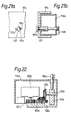
- FIG 19 illustrates monochromatic printing in which the monochromatic ink ribbon cartridge 129 is mounted in the cartridge holder 115.
- the monochromatic ink ribbon cartridge 129 is formed in the same way as the multi-colour ink ribbon cartridge 113 except that it does not include the groove 113 c of the multi-colour ink ribbon cartridge 113.
- the monochromatic ink ribbon cartridge 129 is axially supported by its stub shafts which have been inserted in the holes 126 which are provided at the sides of the cartridge holder 115 in the same way as occurs in the case of the multi-colour ink ribbon cartridge 113, the cartridge 129 being urged in the counterclockwise direction by the spring 114.
- the monochromatic ink ribbon cartridge 129 is positioned in the desired position by the positioning member 130 which is mounted on the upper surface of the cartridge holder 115, irrespective of whether the motor unit 116 is present or not.
- the positioning member is arranged to hold the monochromatic ink ribbon cartridge 129 in a position such that it is always out of contact with the thrust member 124 whatever may be the vertical position of the latter.
- the motor unit 116 is in position in the printer and is driven so that a multi-colour ink ribbon cartridge 113 would be rotated in the range 113 h - 113 l by reason of movement of the thrust member 124 in the range 124 h - 124 l , there is no problem because the monochromatic ink ribbon cartridge 129 is not engaged by the thrust member 124.
- the clearance groove 113 c on the lower surface of the multi-colour ink ribbon cartridge 113 is such that there will never be engagement between the positioning member 130 and the multi-colour ink ribbon cartridge 113 so that pivotal movement of the multi-colour ink ribbon cartridge 113 is not prevented by the positioning member 130.
- no electrical detecting means are required for detecting whether the cartridge is monochrome or multi-colour.
- Figure 21 illustrates a fourth embodiment which employs a bayonet type method of securing a motor unit 116 a to the printer.
- the carriage 111 c has a hole 111 a to receive therein an engagement portion 127 a formed at the left hand end of a lock pin 127 mounted in the motor unit 116, the lock pin 127 having a manually engageable lock lever 128.
- the motor unit 116 can be fixed to the carriage 111 c .
- the carriage 111 c has sloping portions 111 b on opposite sides of the hole 111 a so as to assist the smooth rotation of the engagement portion 127 a of the lock pin 127 into and out of the locked position.
- a motor unit 116 b contains a motor 121 b having a motor gear 121 c .
- the motor gear 121 c meshes with a gear wheel 122 a which is integral with a bevel gear 122 b .
- the bevel gear 122 b meshes with a bevel gear 122 c fixed to a shaft 122 d which is rotatably mounted in the casing of the motor unit 116 b .
- a disc cam 123 c is fixedly mounted on the shaft 122 d and engages a thrust member 124 a .
- the profile of the disc cam 123 c may be the same as that of the cam 123 shown in Figure 18.
- the motor unit 116 may be installed merely by pushing it into position in the carriage 111 with the result that the motor unit 116 can be installed at any time and by any one without any tool. Further, since the motor unit 116 is installed in the carriage 111, it is not necessary to provide a larger printer as compared with a monochromatic printer, and therefore it is possible to provide a compact multi-colour printer.
- the driving means constituted by the motor 121 and the transmission means 121 a , 122, 123, 124 for selecting the required colour are held within one unit, namely the motor unit 116, it is possible to employ a smaller carriage than that normally used in a monochromatic printer, so that it is possible to move the carriage at a high speed and to position the ink ribbon cartridge with high accuracy.
Claims (16)
- Drucker mit einem Druckkopf (4), einem Kassettenhalter (15) zur lösbaren Halterung einer Mehrfarb-Farbbandkassette (18), die ein Farbbandmaterial (17) mit unterschiedlich gefärbten Farbbandteilen (17a, 17b, 17c, 17d) enthält, und mit einer die Positionen einer in dem Kassettenhalter (15) gehaltenen Mehrfarb-Farbbandkassette (18) und des Druckkopfes (4) mittels einer Antriebsübertragungseinrichtung (13, 14) relativ zueinander einstellenden Antriebseinrichtung (19) zur Ausrichtung eines ausgewählten Farbbandteils (17a, 17b, 17c, 17d) des Farbbandmaterials (17) und des Druckkopfes (4) zueinander zum Drucken,
dadurch gekennzeichnet,
daß der Kassettenhalter (15) auch zur lösbaren Halterung einer ein Monochrom-Farbband enthaltenden Kassette eingerichtet ist und daß die Antriebseinrichtung (19) aus dem Drucker frei entfernbar ist, wobei nur monochromes Drucken ermöglicht ist, wenn die Antriebseinrichtung (19) aus dem Drucker entfernt ist, und wahlweise entweder mehrfarbiges oder monochromes Drucken ermöglicht ist, wenn die Antriebseinrichtung (19) in dem Drucker installiert ist. - Drucker nach Anspruch 1,
dadurch gekennzeichnet,
daß der Kassettenhalter (15) mittels der Antriebsübertragungseinrichtung (13, 14) verschwenkbar ist, um einen ausgewählten Farbbandteil (17a, 17b, 17c, 17d) zu dem Druckkopf (4) auszurichten. - Drucker nach Anspruch 2,
dadurch gekennzeichnet,
daß der Kassettenhalter (15) an einem den Druckkopf (4) und die Antriebsübertragungseinrichtung (13, 14) tragenden Schlitten (5) schwenkbar gelagert ist. - Drucker nach Anspruch 3,
dadurch gekennzeichnet,
daß die Antriebsübertragungseinrichtung (13, 14) ein in dem Schlitten (5) drehbar gelagertes Übertragungszahnrad (13) aufweist, welches mit einem Zahnrad (20) der Antriebseinrichtung (19) in Eingriff steht, wenn letztere ebenfalls in dem Schlitten (5) montiert ist, wobei die Drehung des Übertragungszahnrades (13) eine Schwenkbewegung des Kassettenhalters (15) mittels eines hin- und herbewegbaren Hebels (14) bewirkt. - Drucker nach wenigstens einem der vorhergehenden Ansprüche,
dadurch gekennzeichnet,
daß Mittel (49, 51, 53) vorgesehen sind, die indizieren, ob ein Monochrom-Farbband oder ein Mehrfarb-Farbband in den Kassettenhalter (15) eingebracht ist. - Drucker nach Anspruch 5,
dadurch gekennzeichnet,
daß die letztgenannten Mittel (49, 51, 53) ein Paar von Kontakten (49, 51) umfassen, die bezüglich ihres geöffneten oder geschlossenen Zustandes mittels eines Vorsprungs (53) an einer Mehrfarb-Farbandkassette (18) umschaltbar sind. - Drucker nach wenigstens einem der vorhergehenden Ansprüche,
dadurch gekennzeichnet,
daß Mittel (9, 48, 50) zur Erfassung einer Ausgangsstellung des Kassettenhalters (15) vorgesehen sind. - Drucker nach Anspruch 7, rückbezogen auf Anspruch 3,
dadurch gekennzeichnet,
daß die letztgenannten Mittel (9, 48, 50) ein Paar von Kontakten (48, 50) umfassen, die bezüglich ihres geöffneten oder geschlossenen Zustandes mittels eines Vorsprungs (9) an dem Schlitten (5) umschaltbar sind. - Drucker nach wenigstens einem der vorhergehenden Ansprüche,
gekennzeichnet durch eine die Antriebseinrichtung (61) steuernde Steuerschaltung (70), die mittels eines verstellbaren Widerstandes (67) einstellbar ist. - Drucker nach Anspruch 1,
dadurch gekennzeichnet,
daß der Kassettenhalter (15) Mittel (126) zur schwenkbaren Halterung der Mehrfarb-Farbbandkassette (18) aufweist und daß die Antriebsübertragungseinrichtung (121a, 122, 123, 124) ein von der Antriebseinrichtung (121) bewegtes Schubteil (124) umfaßt, welches an die Mehrfarb-Farbbandkassette (18) angreift, um diese zu verschwenken. - Drucker nach Anspruch 10,
dadurch gekennzeichnet,
daß die Antriebsübertragungseinrichtung (121a, 122, 123, 124) einen Nocken (123) mit einem an dem Schubteil (124) angreifenden Nockenprofil umfaßt. - Drucker nach wenigstens einem der vorhergehenden Ansprüche,
dadurch gekennzeichnet,
daß die Antriebseinrichtung (121) und die Antriebsübertragungseinrichtung (121a, 122, 123, 124) in einer gemeinsamen Einheit (116) montiert sind. - Drucker nach Anspruch 12,
dadurch gekennzeichnet,
daß Bajonettbefestigungssmittel (111a, 111b, 127, 127a, 128) zur Fixierung der gemeinsamen Einheit (116) an einen Schlitten (111c) des Druckers vorgesehen sind. - Drucker, umfassend
eine frei anbringbare und entfernbare Antriebseinrichtung (19) zur Farbauswahl,
einen Farbbandkassettenhalter (15) zur Halterung einer frei entfernbaren und einsetzbaren Mehrfarb-Farbbandkassette (18) oder Monochrom-Farbbandkassette, und
eine die von der Antriebseinrichtung (19) gelieferte Kraft übertragende Kraftübertragungseinrichtung (13, 14) zur Bewegung des Farbbandkassettenhalters (15),
wobei der Drucker so aufgebaut ist, daß bei fehlender Antriebseinrichtung (19) die Monochrom-Farbbandkasette für monochromes Drucken ausgewählt wird, und daß bei vorhandener Antriebseinrichtung (19) entweder die Monochrom-Farbbandkassette oder die Mehrfarb-Farbbandkasette (18) für monochromes oder mehrfarbiges Drucken ausgewählt wird. - Drucker, der zum mehrfarbigen Drucken oder zum monochromen Drucken verwendbar ist, umfassend
eine Farbbandschlittenhalterungseinrichtung, an der eine Druckkopfeinrichtung gehalten ist, eine Farbbandkassetteneinrichtung zur verschiebbaren Halterung einer Monochrom-Farbbandkassette oder einer Mehrfarb-Farbbandkassette, eine Antriebseinheit mit einer Übertragungseinrichtung zur lösbaren Kopplung mit der Farbbandkassettenhalterungseinrichtung und zur Verschiebung der Farbbandkassetteneinrichtung mittels antriebsübertragender Mittel und deren Ausgabe, wobei die Übertragungseinrichtung die Kassettenhalterungseinrichtung zum monochromen Drucken positioniert, wenn die Antriebseinrichtung nicht vorhanden ist, und die Kassettenhalterungseinrichtung zum monochromen Drucken oder zum mehrfarbigen Drucken positioniert, wenn die Antriebseinrichtung vorhanden ist. - Drucker, der entweder zum mehrfarbigen Drucken oder zum monochromen Drucken verwendbar ist, umfassend einen Schlitten (16), an dem ein Druckkopf (4) gehalten ist, einen Farbbandkassettenhalter (15) zur Halterung einer Monochrom-Farbbandkassette oder einer Mehrfarb-Farbbandkassette (18), eine Antriebseinrichtung (19) mit einer Übertragungseinrichtung (13, 14) zur lösbaren Kopplung mit dem Farbbandkassettenhalter (15), um die Mehrfarb-Farbbandkassette (18) durch Übertragung des Antriebs der Antriebseinrichtung (19) zu bewegen, wobei die Übertragungseinrichtung (13, 14) den Farbbandkassettenhalter (15) zum monochromen Drucken positioniert, wenn die Antriebseinrichtung (19) nicht vorhanden ist, und die Übertragungseinrichtung (13, 14) entweder monochromes oder farbiges Drucken ermöglicht, wenn die Antriebseinrichtung (19) vorhanden ist.
Applications Claiming Priority (4)
| Application Number | Priority Date | Filing Date | Title |
|---|---|---|---|
| JP100169/86 | 1986-04-30 | ||
| JP61100169A JPH0696325B2 (ja) | 1986-04-30 | 1986-04-30 | プリンタ |
| JP61115629A JP2547986B2 (ja) | 1986-05-20 | 1986-05-20 | プリンタ |
| JP115629/86 | 1986-05-20 |
Publications (3)
| Publication Number | Publication Date |
|---|---|
| EP0244228A2 EP0244228A2 (de) | 1987-11-04 |
| EP0244228A3 EP0244228A3 (en) | 1989-01-18 |
| EP0244228B1 true EP0244228B1 (de) | 1991-09-11 |
Family
ID=26441253
Family Applications (1)
| Application Number | Title | Priority Date | Filing Date |
|---|---|---|---|
| EP87303816A Expired - Lifetime EP0244228B1 (de) | 1986-04-30 | 1987-04-29 | Drucker für einfarbiges und mehrfarbiges Drucken |
Country Status (5)
| Country | Link |
|---|---|
| US (2) | US4867587A (de) |
| EP (1) | EP0244228B1 (de) |
| KR (1) | KR910002393B1 (de) |
| DE (1) | DE3772829D1 (de) |
| HK (1) | HK42896A (de) |
Families Citing this family (23)
| Publication number | Priority date | Publication date | Assignee | Title |
|---|---|---|---|---|
| DE3772829D1 (de) * | 1986-04-30 | 1991-10-17 | Seiko Epson Corp | Drucker fuer einfarbiges und mehrfarbiges drucken. |
| JPH02231183A (ja) * | 1989-03-03 | 1990-09-13 | Brother Ind Ltd | リボンカセットの揺動装置 |
| DE8904219U1 (de) * | 1989-04-05 | 1990-08-09 | Nixdorf Computer Ag, 4790 Paderborn, De | |
| JPH0780335B2 (ja) * | 1989-11-20 | 1995-08-30 | 富士通株式会社 | リボンカセット |
| US5098208A (en) * | 1990-01-12 | 1992-03-24 | Smith Corona Corporation | Ribbon cassette with integral paper guide |
| US4971463A (en) * | 1990-03-16 | 1990-11-20 | Ncr Corporation | Printer ribbon cassette mounting apparatus |
| JPH045074A (ja) * | 1990-04-24 | 1992-01-09 | Canon Inc | 記録装置 |
| US5160204A (en) * | 1990-04-24 | 1992-11-03 | Canon Kabushiki Kaisha | Ribbon adapter and ribbon cassette capable of mounting the ribbon adapter and recording apparatus |
| US5069563A (en) * | 1990-06-29 | 1991-12-03 | General Ribbon Corporation | Ribbon cartridge mounting movable power switch tab |
| US5122002A (en) * | 1990-06-29 | 1992-06-16 | General Ribbon Corporation | Ribbon cartridge with correction cartridge lock-out circumvention power switch projection |
| US5211491A (en) * | 1991-04-10 | 1993-05-18 | Eastman Kodak Company | Thermal transfer cartridge integral lock |
| NL9100721A (nl) * | 1991-04-25 | 1992-11-16 | Merlin Ctc Prod | Lint-cassette. |
| JP3404777B2 (ja) * | 1991-12-25 | 2003-05-12 | セイコーエプソン株式会社 | プリンタ及び該プリンタの制御方法 |
| US5468078A (en) * | 1991-12-25 | 1995-11-21 | Seiko Epson Corporation | Printer color ink ribbon positioning control |
| US5360279A (en) * | 1991-12-25 | 1994-11-01 | Seiko Epson Corporation | Printer ink ribbon control |
| US5370469A (en) * | 1992-07-01 | 1994-12-06 | Oki Electric Industry Co., Ltd. | Cassette holder assembly |
| US5383733A (en) * | 1992-07-24 | 1995-01-24 | Summagraphics Corporation | Ribbon cassette for a printer |
| US5267802A (en) * | 1992-07-24 | 1993-12-07 | Summagraphics Corporation | Ribbon cassette storage and transfer apparatus for a printer |
| JP2923160B2 (ja) * | 1993-02-25 | 1999-07-26 | アルプス電気株式会社 | 熱転写プリンタ |
| JPH0723557U (ja) * | 1993-10-12 | 1995-05-02 | 三菱鉛筆株式会社 | インクリボンサブカートリッジ |
| JP3383764B2 (ja) * | 1998-02-05 | 2003-03-04 | 船井電機株式会社 | プリンタシステム |
| JP2006018588A (ja) * | 2004-07-01 | 2006-01-19 | Canon Inc | 画像形成装置及びその制御方法、並びにプログラム及び記憶媒体 |
| CN108724992B (zh) * | 2017-04-13 | 2020-05-15 | 精工爱普生株式会社 | 墨带收卷机构和带印刷装置 |
Family Cites Families (12)
| Publication number | Priority date | Publication date | Assignee | Title |
|---|---|---|---|---|
| US4425046A (en) * | 1980-09-22 | 1984-01-10 | Dataproducts Corporation | Ribbon cassette and sensor assembly |
| DE3301933C2 (de) * | 1983-01-21 | 1985-03-07 | Triumph-Adler Aktiengesellschaft für Büro- und Informationstechnik, 8500 Nürnberg | Vorrichtung zum Farbbandhub und -transport in Schreib- und ähnlichen Maschinen |
| JPS6064884A (ja) * | 1983-09-20 | 1985-04-13 | Canon Inc | 印字装置 |
| JPS60120086A (ja) * | 1983-11-30 | 1985-06-27 | Tokyo Electric Co Ltd | リボン位置切換装置 |
| JPS60174670A (ja) * | 1984-02-21 | 1985-09-07 | Canon Inc | 記録装置 |
| GB8405455D0 (en) * | 1984-03-01 | 1984-04-04 | Data Recording Instr Co | Printing apparatus |
| JPS60183176A (ja) * | 1984-03-02 | 1985-09-18 | Canon Inc | 熱転写プリンタ |
| US4586837A (en) * | 1984-08-27 | 1986-05-06 | International Business Machines Corp. | Ink ribbon cartridge indication system for printer |
| JPS6172572A (ja) * | 1984-09-17 | 1986-04-14 | Tokyo Electric Co Ltd | タイプライタ |
| JPS61104884A (ja) * | 1984-10-26 | 1986-05-23 | Tokyo Electric Co Ltd | 印字機のリボン切換装置 |
| JPS6250183A (ja) * | 1985-08-29 | 1987-03-04 | Toshiba Corp | プリンタのリボン駆動制御方式 |
| DE3772829D1 (de) * | 1986-04-30 | 1991-10-17 | Seiko Epson Corp | Drucker fuer einfarbiges und mehrfarbiges drucken. |
-
1987
- 1987-04-29 DE DE8787303816T patent/DE3772829D1/de not_active Expired - Lifetime
- 1987-04-29 EP EP87303816A patent/EP0244228B1/de not_active Expired - Lifetime
- 1987-04-30 US US07/045,005 patent/US4867587A/en not_active Expired - Lifetime
- 1987-04-30 KR KR1019870004212A patent/KR910002393B1/ko not_active IP Right Cessation
-
1989
- 1989-07-13 US US07/379,319 patent/US5082381A/en not_active Expired - Lifetime
-
1996
- 1996-03-14 HK HK42896A patent/HK42896A/xx not_active IP Right Cessation
Also Published As
| Publication number | Publication date |
|---|---|
| KR910002393B1 (ko) | 1991-04-22 |
| EP0244228A3 (en) | 1989-01-18 |
| US4867587A (en) | 1989-09-19 |
| DE3772829D1 (de) | 1991-10-17 |
| US5082381A (en) | 1992-01-21 |
| EP0244228A2 (de) | 1987-11-04 |
| HK42896A (en) | 1996-03-22 |
| KR870009858A (ko) | 1987-11-30 |
Similar Documents
| Publication | Publication Date | Title |
|---|---|---|
| EP0244228B1 (de) | Drucker für einfarbiges und mehrfarbiges Drucken | |
| US4676675A (en) | Media thickness compensating device for a printer | |
| US8029130B2 (en) | Hand-held printer with capping device | |
| EP0734879B1 (de) | Drucker und zusammengesetzte Kassette für diesen Drucker, bestehend aus Druckband- und Farbbandkassette | |
| US4797017A (en) | Wire dot matrix printer capable of printing letters on a plurality of superposed sheets of paper | |
| GB2067472A (en) | Electronic typewriter | |
| EP0048418B2 (de) | Anordnung mit mehreren Schaltstellungen für eine Bandkassette | |
| EP0337275B1 (de) | Drucker mit Papierdickendetektor | |
| US4368993A (en) | Replaceable assembly for multicolor printing | |
| US4393455A (en) | Modular electronic measuring and printing unit | |
| US4693619A (en) | Stepping motor operated positioning device for a ribbon lifter in a printer | |
| US5080511A (en) | Serial type color printer used with ink ribbon cassette | |
| EP0910156B1 (de) | Gleichstrommotor für einen geschlossenen Regelkreis | |
| US5059047A (en) | Apparatus for controlling reversing duration of hammer bank in shuttle printer | |
| US4842427A (en) | Plotting mechanism mounted on a ribbon cassette for typewriters or office machines | |
| JPH0143507B2 (de) | ||
| JPH078228Y2 (ja) | プリンタにおけるインクリボン位置決め装置 | |
| GB2148796A (en) | Recording apparatus | |
| JPH02139271A (ja) | プリンタ | |
| JPH0612519Y2 (ja) | 反射濃度計 | |
| JPH0462073A (ja) | プリンタ | |
| GB2050661A (en) | Electrically-controlled Printing Apparatus | |
| JPH0341356B2 (de) | ||
| JPH0541017Y2 (de) | ||
| JPS63147670A (ja) | プリンタの印字位置制御装置 |
Legal Events
| Date | Code | Title | Description |
|---|---|---|---|
| PUAI | Public reference made under article 153(3) epc to a published international application that has entered the european phase |
Free format text: ORIGINAL CODE: 0009012 |
|
| AK | Designated contracting states |
Kind code of ref document: A2 Designated state(s): DE FR GB |
|
| PUAL | Search report despatched |
Free format text: ORIGINAL CODE: 0009013 |
|
| AK | Designated contracting states |
Kind code of ref document: A3 Designated state(s): DE FR GB |
|
| 17P | Request for examination filed |
Effective date: 19890621 |
|
| 17Q | First examination report despatched |
Effective date: 19901214 |
|
| GRAA | (expected) grant |
Free format text: ORIGINAL CODE: 0009210 |
|
| AK | Designated contracting states |
Kind code of ref document: B1 Designated state(s): DE FR GB |
|
| REF | Corresponds to: |
Ref document number: 3772829 Country of ref document: DE Date of ref document: 19911017 |
|
| ET | Fr: translation filed | ||
| PLBE | No opposition filed within time limit |
Free format text: ORIGINAL CODE: 0009261 |
|
| STAA | Information on the status of an ep patent application or granted ep patent |
Free format text: STATUS: NO OPPOSITION FILED WITHIN TIME LIMIT |
|
| 26N | No opposition filed | ||
| REG | Reference to a national code |
Ref country code: GB Ref legal event code: IF02 |
|
| PGFP | Annual fee paid to national office [announced via postgrant information from national office to epo] |
Ref country code: FR Payment date: 20060410 Year of fee payment: 20 |
|
| PGFP | Annual fee paid to national office [announced via postgrant information from national office to epo] |
Ref country code: GB Payment date: 20060426 Year of fee payment: 20 |
|
| PGFP | Annual fee paid to national office [announced via postgrant information from national office to epo] |
Ref country code: DE Payment date: 20060427 Year of fee payment: 20 |
|
| REG | Reference to a national code |
Ref country code: GB Ref legal event code: PE20 |
|
| PG25 | Lapsed in a contracting state [announced via postgrant information from national office to epo] |
Ref country code: GB Free format text: LAPSE BECAUSE OF EXPIRATION OF PROTECTION Effective date: 20070428 |