EP0244035B2 - Procédé et dispositif pour obtenir des lignes de marquage sur une nappe de fibres minérales contenant un liant - Google Patents
Procédé et dispositif pour obtenir des lignes de marquage sur une nappe de fibres minérales contenant un liant Download PDFInfo
- Publication number
- EP0244035B2 EP0244035B2 EP87200792A EP87200792A EP0244035B2 EP 0244035 B2 EP0244035 B2 EP 0244035B2 EP 87200792 A EP87200792 A EP 87200792A EP 87200792 A EP87200792 A EP 87200792A EP 0244035 B2 EP0244035 B2 EP 0244035B2
- Authority
- EP
- European Patent Office
- Prior art keywords
- heating
- roll
- fibre web
- mineral fibre
- roller
- Prior art date
- Legal status (The legal status is an assumption and is not a legal conclusion. Google has not performed a legal analysis and makes no representation as to the accuracy of the status listed.)
- Expired - Lifetime
Links
- 239000011230 binding agent Substances 0.000 title claims abstract description 18
- 229910052500 inorganic mineral Inorganic materials 0.000 title claims abstract 19
- 239000011707 mineral Substances 0.000 title claims abstract 19
- 238000000034 method Methods 0.000 title claims description 17
- 238000010438 heat treatment Methods 0.000 claims abstract description 100
- 239000000835 fiber Substances 0.000 claims abstract description 25
- 230000002093 peripheral effect Effects 0.000 claims abstract description 13
- 239000000463 material Substances 0.000 claims description 17
- 238000012546 transfer Methods 0.000 claims description 11
- 238000004519 manufacturing process Methods 0.000 claims description 9
- 230000009471 action Effects 0.000 claims description 4
- 239000003779 heat-resistant material Substances 0.000 claims 3
- 230000000717 retained effect Effects 0.000 claims 1
- 238000000354 decomposition reaction Methods 0.000 abstract description 11
- 230000000694 effects Effects 0.000 abstract description 6
- 239000002184 metal Substances 0.000 abstract description 2
- 238000005096 rolling process Methods 0.000 abstract 1
- 239000002557 mineral fiber Substances 0.000 description 83
- 230000035515 penetration Effects 0.000 description 9
- 230000015572 biosynthetic process Effects 0.000 description 5
- 239000011888 foil Substances 0.000 description 5
- 238000013461 design Methods 0.000 description 4
- 238000007373 indentation Methods 0.000 description 3
- 238000003860 storage Methods 0.000 description 3
- 238000003466 welding Methods 0.000 description 3
- KXGFMDJXCMQABM-UHFFFAOYSA-N 2-methoxy-6-methylphenol Chemical group [CH]OC1=CC=CC([CH])=C1O KXGFMDJXCMQABM-UHFFFAOYSA-N 0.000 description 2
- 239000010425 asbestos Substances 0.000 description 2
- 230000004323 axial length Effects 0.000 description 2
- 239000002131 composite material Substances 0.000 description 2
- 238000010276 construction Methods 0.000 description 2
- 238000001816 cooling Methods 0.000 description 2
- 230000006735 deficit Effects 0.000 description 2
- 238000002845 discoloration Methods 0.000 description 2
- 238000005265 energy consumption Methods 0.000 description 2
- 230000006872 improvement Effects 0.000 description 2
- 239000011810 insulating material Substances 0.000 description 2
- 239000010410 layer Substances 0.000 description 2
- 239000005011 phenolic resin Substances 0.000 description 2
- 229920001568 phenolic resin Polymers 0.000 description 2
- 239000002985 plastic film Substances 0.000 description 2
- 230000005855 radiation Effects 0.000 description 2
- 229910052895 riebeckite Inorganic materials 0.000 description 2
- 230000001360 synchronised effect Effects 0.000 description 2
- 230000003313 weakening effect Effects 0.000 description 2
- 230000008859 change Effects 0.000 description 1
- 239000004020 conductor Substances 0.000 description 1
- 230000001276 controlling effect Effects 0.000 description 1
- 230000001186 cumulative effect Effects 0.000 description 1
- 238000011982 device technology Methods 0.000 description 1
- 238000004090 dissolution Methods 0.000 description 1
- 239000002706 dry binder Substances 0.000 description 1
- 230000002349 favourable effect Effects 0.000 description 1
- 239000002657 fibrous material Substances 0.000 description 1
- 238000007654 immersion Methods 0.000 description 1
- 230000006698 induction Effects 0.000 description 1
- 238000003780 insertion Methods 0.000 description 1
- 230000037431 insertion Effects 0.000 description 1
- 238000003475 lamination Methods 0.000 description 1
- 238000012423 maintenance Methods 0.000 description 1
- 239000012778 molding material Substances 0.000 description 1
- 230000000149 penetrating effect Effects 0.000 description 1
- 229920006255 plastic film Polymers 0.000 description 1
- 230000009467 reduction Effects 0.000 description 1
- 230000001105 regulatory effect Effects 0.000 description 1
- 239000002344 surface layer Substances 0.000 description 1
- 229920001169 thermoplastic Polymers 0.000 description 1
- 238000004804 winding Methods 0.000 description 1
Images


Classifications
-
- E—FIXED CONSTRUCTIONS
- E04—BUILDING
- E04D—ROOF COVERINGS; SKY-LIGHTS; GUTTERS; ROOF-WORKING TOOLS
- E04D13/00—Special arrangements or devices in connection with roof coverings; Protection against birds; Roof drainage ; Sky-lights
- E04D13/16—Insulating devices or arrangements in so far as the roof covering is concerned, e.g. characterised by the material or composition of the roof insulating material or its integration in the roof structure
- E04D13/1606—Insulation of the roof covering characterised by its integration in the roof structure
- E04D13/1612—Insulation of the roof covering characterised by its integration in the roof structure the roof structure comprising a supporting framework of roof purlins or rafters
- E04D13/1625—Insulation of the roof covering characterised by its integration in the roof structure the roof structure comprising a supporting framework of roof purlins or rafters with means for supporting the insulating material between the purlins or rafters
-
- B—PERFORMING OPERATIONS; TRANSPORTING
- B44—DECORATIVE ARTS
- B44B—MACHINES, APPARATUS OR TOOLS FOR ARTISTIC WORK, e.g. FOR SCULPTURING, GUILLOCHING, CARVING, BRANDING, INLAYING
- B44B5/00—Machines or apparatus for embossing decorations or marks, e.g. embossing coins
- B44B5/02—Dies; Accessories
- B44B5/028—Heated dies
-
- B—PERFORMING OPERATIONS; TRANSPORTING
- B44—DECORATIVE ARTS
- B44B—MACHINES, APPARATUS OR TOOLS FOR ARTISTIC WORK, e.g. FOR SCULPTURING, GUILLOCHING, CARVING, BRANDING, INLAYING
- B44B7/00—Machines, apparatus or hand tools for branding, e.g. using radiant energy such as laser beams
-
- E—FIXED CONSTRUCTIONS
- E04—BUILDING
- E04B—GENERAL BUILDING CONSTRUCTIONS; WALLS, e.g. PARTITIONS; ROOFS; FLOORS; CEILINGS; INSULATION OR OTHER PROTECTION OF BUILDINGS
- E04B1/00—Constructions in general; Structures which are not restricted either to walls, e.g. partitions, or floors or ceilings or roofs
- E04B1/62—Insulation or other protection; Elements or use of specified material therefor
- E04B1/74—Heat, sound or noise insulation, absorption, or reflection; Other building methods affording favourable thermal or acoustical conditions, e.g. accumulating of heat within walls
- E04B1/76—Heat, sound or noise insulation, absorption, or reflection; Other building methods affording favourable thermal or acoustical conditions, e.g. accumulating of heat within walls specifically with respect to heat only
- E04B1/7654—Heat, sound or noise insulation, absorption, or reflection; Other building methods affording favourable thermal or acoustical conditions, e.g. accumulating of heat within walls specifically with respect to heat only comprising an insulating layer, disposed between two longitudinal supporting elements, e.g. to insulate ceilings
- E04B1/7658—Heat, sound or noise insulation, absorption, or reflection; Other building methods affording favourable thermal or acoustical conditions, e.g. accumulating of heat within walls specifically with respect to heat only comprising an insulating layer, disposed between two longitudinal supporting elements, e.g. to insulate ceilings comprising fiber insulation, e.g. as panels or loose filled fibres
- E04B1/7662—Heat, sound or noise insulation, absorption, or reflection; Other building methods affording favourable thermal or acoustical conditions, e.g. accumulating of heat within walls specifically with respect to heat only comprising an insulating layer, disposed between two longitudinal supporting elements, e.g. to insulate ceilings comprising fiber insulation, e.g. as panels or loose filled fibres comprising fiber blankets or batts
-
- E—FIXED CONSTRUCTIONS
- E04—BUILDING
- E04D—ROOF COVERINGS; SKY-LIGHTS; GUTTERS; ROOF-WORKING TOOLS
- E04D13/00—Special arrangements or devices in connection with roof coverings; Protection against birds; Roof drainage ; Sky-lights
- E04D13/16—Insulating devices or arrangements in so far as the roof covering is concerned, e.g. characterised by the material or composition of the roof insulating material or its integration in the roof structure
-
- E—FIXED CONSTRUCTIONS
- E04—BUILDING
- E04B—GENERAL BUILDING CONSTRUCTIONS; WALLS, e.g. PARTITIONS; ROOFS; FLOORS; CEILINGS; INSULATION OR OTHER PROTECTION OF BUILDINGS
- E04B1/00—Constructions in general; Structures which are not restricted either to walls, e.g. partitions, or floors or ceilings or roofs
- E04B1/62—Insulation or other protection; Elements or use of specified material therefor
- E04B1/74—Heat, sound or noise insulation, absorption, or reflection; Other building methods affording favourable thermal or acoustical conditions, e.g. accumulating of heat within walls
- E04B2001/741—Insulation elements with markings, e.g. identification or cutting template
Definitions
- the invention relates to a method for applying marking lines to a mineral fiber web containing binder, according to the preamble of claim 1.
- EP-A-0 10 1 376 (DE-A-32 29 601).
- the marking lines to be applied there run in the longitudinal direction of the mineral fiber web, that is to say in its transport or production direction.
- a penetration marking is generated in such a way that a sharply focused flame or a sharply focused hot air jet with a temperature of, for example, 600 ° C. is directed onto the surface of the mineral fiber web, which in its core area, the binder on the surface of the mineral fiber web is heated to its decomposition temperature and thus discolored.
- a marking line running parallel to the edge in the longitudinal direction of the web it is therefore only necessary to arrange a corresponding hot air nozzle or flame lance above the running mineral fiber web.
- EP-A-0 119 801 discloses a method and an apparatus for introducing markings, which represent the “R” value, the size, the thickness and other relevant information, into a fiber felt.
- the aim here is to incorporate the markings as deeply as possible into the interior of the fiber felt, so that not only the surface itself but also the layers underneath are permanently changed in color and structure by the treatment. This deep insertion of the markings takes place with an open flame or with heat radiation, which is generated inside the roller and penetrates deeply into the web to be marked via template openings.
- this heating device in the form of a roller does not serve to apply marking lines, but rather to produce tack points penetrating deeply into the material of the mineral fiber web by locally softening the mineral fibers and thus welding them together.
- the circumferential surface of the roller has rows of openings through which hot gas at a high temperature usually emerges in a lance shape up to 1000 ° C.
- the peripheral surface of the roller lies on the surface of the mineral fiber web, and the roller rotates at a speed which corresponds to the transport speed of the mineral fiber web.
- a hot gas outlet through a row of holes is only permitted if it lies in the region of the lower vertex of the roller, so that the hot gas lances into the mineral fiber web from each opening and forms tack points.
- the depth of penetration can be further promoted by the negative pressure generated on the opposite side of the mineral fiber web.
- Such a device is not used to apply marking lines and is also not suitable for generating marking lines which practically do not influence the behavior of the mineral fiber material at the marking point.
- the large penetration depth desired in the known case can be reduced by throttling the hot gas supply, but it is considerable in any case if so much energy is to be introduced by a local hot gas flow during the contact time that a rich discoloration results.
- the lateral limitation of the area of action of the hot gas is difficult to control, especially since the action takes place in the course of the rotation of the roller and thus with a changing direction.
- lateral flow components play a role, which in the edge region of the marking still partially decompose the binder and thus lead to an unsharp boundary of the marking.
- a roller as the heating device.
- the peripheral surface of the roller is formed by several radially adjustable segments, in each of which a heating strip running parallel to the axis of the roller is arranged. These are provided with axially parallel heating strips distributed on the circumference
- the roller does not serve to apply marking lines to a mineral fiber web containing binding agents, but rather to weld two thin thermoplastic plastic films to one another in strip-shaped areas running transversely to their direction of transport, the circumferential speed and therefore the distance between the strip-shaped ones being possible due to the radial adjustability of the segments during operation Welding zones is changeable.
- the two plastic films lie on top of each other and are guided together over the roller so that they set the roller in rotation as a result of their transport movement due to friction.
- the heat transfer from the respective heating strip to the foils must be so great that the foil lying directly on the roller is melted in the region of the heating strip and the other foil supported by a counter roller is at least melted, so that a permanent weld connection is created.
- This known film welding device is not suitable for applying marking lines to a mineral fiber web which have practically no effect on the properties of the fiber material. Because when marking lines are applied to a mineral fiber web, two thin, less compressible and smooth surface foils should not be welded together, but rather a relatively thick mineral fiber web made of a material that is easy to compress and has no closed surface and that only has a heat input limited to its upper layers exposed to the extent that clearly recognizable marking lines are formed as a result of the decomposition and discoloration of the binder caused by the heating.
- the object of the invention is to provide a method and a device which allow the application of marking lines running transversely to the side edges on a surface of a mineral fiber web in the simplest and most reliable manner possible allow and with a low penetration depth of the decomposition phenomena enable the placement of cleanly delineated marking lines at exact and constant distances from each other.
- the roller can be rotated at a circumferential speed that deviates slightly from the transport speed of the mineral fiber web, in order to compensate for such small inaccuracies due to the plant conditions between the roller and the mineral fiber web.
- the roller is pressed according to claim 2 to form a trough in the surface of the mineral fiber web.
- the heat transfer can thus be adapted to the need for the formation of a clean marking without excessive heat input into the mineral fiber web: at a very slow transport speed, the roller is only slightly pressed and thus the contact pressure and the contact path are reduced, so that the desired heat input takes place in view of the relatively long contact time available at low transport speed, while at high transport speed the heat transfer in the short tent available is increased accordingly by increasing the contact pressure and lengthening the contact path.
- the marking is expediently already carried out on the production line, the speed of which is dictated by the production conditions, there is thus a degree of freedom in adapting the marking conditions to the respective production speed in such a way that sufficient, but not excessive, heat input into the mineral fiber web occurs at all production speeds that occur .
- the heat input into the mineral fiber web can also be completely or additionally influenced by controlling the temperature of the heating zones.
- the thermal load on the roller on the one hand and the thermal load on the mineral fiber web at the point of contact with the heating zones on the other hand there is a relatively narrow optimum temperature range which should be maintained as far as possible.
- the different setting of the penetration depth of the roller in the surface of the mineral fiber web enables a corresponding adjustment of the heat input without the temperature of the heating zones having to leave the optimal operating range.
- the measure of claim 4 also enables a considerable simplification of the structural design of a device required to carry out the method, since a rotary drive can be omitted for operation and at most a simple rotary drive is required for preheating the roller in order to ensure uniform heating to ensure the heating zones distributed over the circumference of the roller.
- the measure of claim 5 results in broken, so to speak broken lines. These generally serve their purpose and make it possible to work with individual, shorter, spaced-apart heating zones which, with regard to their smaller linear expansion, avoid problems with addition of the thermal expansion in the longitudinal direction. In addition, the energy consumption is reduced and any impairments are avoided since material consistency due to tensile or compressive loading of the fibers in the winding is avoided in that there is completely unaffected material in sections.
- a device which is particularly suitable for carrying out the method according to the invention is characterized in detail by the characterizing features of claim 7.
- Heating rods form a particularly favorable constructive possibility for forming the heating zones required according to the method.
- Straight heating rods can be used to form straight line markings; however, other markings such as rasters, monograms or the like can also be generated if the heating rods are shaped in accordance with the respectively desired marking contour.
- the measures of claim 8 ensure that energy losses due to heat radiation or heat conduction from the heating rods are minimized, while at the same time, in particular a lateral bordering of the heating rods due to the good heat-insulating material of the holder results in a sharp delimitation of the heating zones and ensures clean edges of the marking lines.
- the heating rods protrude a small amount from the circumferential surface of the roller, the air surrounding the heating rods ensures cooling of the mineral fiber material adjacent to the marking strips during the marking and thus promotes a clean formation of the edges of the marking lines. Furthermore, it increases especially at deeper into the mineral fiber web Pressed roller the entrainment effect of the mineral fiber material on the roller, since protruding edges of the heating elements favor the entrainment effect.
- heating rods can be heated by greased electric tubular heating elements, there is a constructive freedom of movement for the design of the heating rods.
- a commercially available tubular heater can be used, which results in low procurement costs and high operational reliability, without the outer contour of which would restrict the free movement of the heating rods.
- any type of suitable heating device including a contactless one, e.g. B. Induction heating can be used as long as it is ensured that the desired heating can take place locally in the heating zones.
- a particularly advantageous design results from the use of an inner supporting body for the roller in the form of a cylindrical polygon.
- Each straight surface of the polygon can be a support for the holder and the internals of a heating element in a structurally simple manner.
- the drive speed of the roller can be synchronized with that of the conveyor or production belt in a simple manner by using a DC motor to drive the roller.
- an electric motor with a freewheel which is expediently designed as a three-phase motor, is preferably provided in the heating phase for a continuous slow rotation of the roller at non-critical speed for uniform heating of the Heating rods ensures, and its freewheeling allows the motor to overtake as soon as the roller lies on the mineral fiber web and is driven by it at increased speed. With each interruption in operation, the electric motor then continues to rotate the lifted roller in order to ensure that the heating elements are always heated uniformly.
- the bearing frame of the roller is held in its height position by means of an actuating drive.
- the indentation of the roller on the mineral fiber web can be precisely adjusted at any time in such a way that the markings are optimally formed as a function of the current transport speed of the mineral fiber web.
- the actuator expediently has at least one threaded spindle, which can be driven, for example, by an electric stepper motor and thus ensures problem-free fine adjustment and its maintenance by remote control.
- the threaded spindles preferably engage a holding frame for the lifting and lowering storage frame, which is likewise designed to be raised and lowered. According to claim 15, this holding frame is connected to the storage frame via a pressure medium drive and the latter can be moved between an operating position and a rest position by the pressure medium drive.
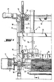
- Fig. 1 denotes a roller, as shown in Fig. 2 enlarged with details and in Fig. 3 schematically simplified perspective.
- Fig. 1 only the left end of the roller 1 is illustrated in the example, it being understood that there is a corresponding bearing of the roller at the opposite end.
- Fig. 1 denotes a shaft, which is connected to the roller 1 and serves to support it.
- the roller 1 is mounted on the shaft 2 on a bearing frame 3 with bearings 4 on both sides. Outside the bearing 4, the shaft 2 projects into an electrical connection box 5, in which, in a known manner, a power supply for the rotating parts of the roller 1 via schematically illustrated slip rings 6 he follows.
- the roller 1 can be rotated in the bearing 4 via the shaft 2.
- An electric motor 7 is provided as a rotary drive, which is mounted on the bearing frame 3 and drives a drive gear 9, which is connected to the shaft 2 in a rotationally fixed manner, with an output pinion 8 via a toothed belt or the like. In this way, the roller 1 can be rotated in the bearings 4.
- the storage rack 3 is up and down on columns 10 of a stationary portal, generally designated 11 movably guided.
- a holding frame 12 with a cross member 13 is guided up and down on the columns 10.
- the bearing frame 3 is held on the holding frame 12 via pressure medium drives 14 in the form of, for example, pneumatic cylinders 15 which are mounted on the crossmember 13 and whose piston rods 16 act on the bearing frame 3 at 17.
- pressure medium drives 14 in the form of, for example, pneumatic cylinders 15 which are mounted on the crossmember 13 and whose piston rods 16 act on the bearing frame 3 at 17.
- the holding frame 12 is in turn connected via actuators 18 to a cross member 19 of the fixed portal 11.
- the actuators 18, for example in the form of threaded spindles 20, are actuated by an electric motor 21, for example in the form of a stepping motor and gear 22.
- the height of the crossmember 13 and the holding frame 12 can be finely adjusted in a desired position via the actuating drives 18.
- the piston rod 16 of the pressure medium drives 14 is extended, this results in a corresponding specific height position of the roller 1.
- the roller 1 can be lowered into this predetermined operating position or raised to a rest position without the holding frame 12 changing in its position and thus the set fine adjustment is canceled.
- the lower region of the roller 1 is shown in an end view and partly in section in the operating position.
- the roller 1 has a support body 23 in the form of a polygon, in the example in the form of a 20-corner, on the flat lateral surfaces 24 of which holders 25 for heating rods 26 are held by screws 27.
- the heating rods 26 have a bearing body 28 arranged in the interior of the holder 25 and also marking ribs 30 protruding from the peripheral surface of the roller 1, designated 29.
- the heating rods 26 consist of a suitable, good heat-conducting metal and have in the region of their bearing body 28 a recess 31, which is round in the example, for receiving conventional tubular heating elements 32, similar to heating coils of immersion heaters.
- the heating rods 26 are formed in a plane 33 which is radial to the axis of the roller 1, the parts 26a and 26b of the heating rods 26 thus formed being connected to one another by suitable countersunk screws 34 and 35.
- the tubular heaters 32 After the tubular heaters 32 have been installed in the recess 31 of the two open parts 26a and 26b of the heating rods 26, the heating rods 26 are preassembled by inserting the screws 34 and 35 and inserted into the holder 25. Then the holder 25 provided on its outer circumference with cover plates 36 which overlap shoulders 37 of the bearing body 28 of each heating element 26 and thus hold it securely in the holder 25.
- the holder 25 and the cover plates 36 consist of a suitable, poorly heat-conducting material such as a fibrous or fibrous molding material based on asbestos or asbestos substitute, in order to avoid heat losses from the heating rods 26 and the areas of the peripheral surface 29, both of which are rare for the marking ribs 30 before heating and to protect heat transfer to the mineral fiber material of the mineral fiber web designated by 38.
- a suitable, poorly heat-conducting material such as a fibrous or fibrous molding material based on asbestos or asbestos substitute
- Each heating rod 26 has a recess 39 for receiving an earth cable. At least one of the heating rods 26 also has a recess 40 in the vicinity of its marking rib 30 for receiving a thermal sensor.
- the temperature control using the thermal sensor and the power supply to the tubular heating element 32 is carried out via the slip rings 6 (cf. FIG. 1).
- temperature control using thermal sensors can also be omitted, and instead only the power supply to the tubular heating elements 32 can be regulated. In stationary operation, a certain temperature then results which is suitable for producing the markings, the optimum formation of the markings being able to be set by the degree of impression of the roller 1 in the mineral fiber web 38.
- the marking ribs 30 of the heating rods 26 and possibly the heating rods themselves extend only over part of the axial length of the roller 1, so that a plurality of marking ribs 30 form an interrupted line along a surface line of the roller 1 and at an axial distance are arranged from each other. If the length of the heating rods 26 is limited to the axial extent of the marking ribs 30, this results in a plurality of individual, shorter heating rods with easily controllable thermal expansions.
- the heating rods 26 can then be connected to one another by lines or a piece of tubular heating element 32 which is insulated on the corresponding circumference and which connects the heating rods 26 approximately in an arc shape. If, on the other hand, the heating rods 26 run over the entire axial length of the roller 1 and only the gaps required to interrupt the marking are present between the protruding sections of the heating rods 26, which are referred to as marking ribs 30, the result is a very robust and stable construction, in which the tubular heating elements 32 are embedded in the heating rods 26 over their entire length.
- the mineral fiber web 38 is preferably of a type such as is explained in the context of DE-A-36 12 858.
- it may be an unclad mineral fiber web 38 with a width of 1200 mm, a nominal thickness of 100 mm and a length of 6 m handeil.
- the bulk density may be between 10 and 30 kg / m3, in particular between 14 and 25 kg / m3, and in the specific case of 18 kg / m3.
- a particularly suitable binder is phenolic resin in a proportion of 6 to 7% by weight of the dry binder in the product, in which case the binder content of phenolic resin may be 6.6% by weight (dry) in the example.
- the properties and the use of such a mineral fiber web 38 and with regard to other elements reference may be made in full to DE-A-36 12 858.
- the roller 1 In operation, when the piston rods 16 are retracted, the roller 1 is set in rotation by the electric motor 7 above the surface of the mineral fiber web 38 denoted by 41, the heating rods 26 being preheated to a desired temperature, optionally monitored by the thermal sensors, by supplying current to the tubular heating elements 32.
- the rotation in the preheating phase ensures uniform heat losses of the individual heating rods 26 and marking ribs 30 and thus their uniform heating without individual temperature control on each individual heating rod 26.
- the piston rods 16 are extended and the roller 1 is lowered onto the surface 41 of the mineral fiber web 38, whereby by means of the electric motor 21 and the actuating drives 18, a fine adjustment of the high position of the roller 1 over the mineral fiber web 38 can take place.
- the setting is expediently chosen so that the marking ribs 30 on the circumference of the roller 1 press the surface 41 of the mineral fiber web 38 to form a trough 42.
- the surface 41 of the mineral fiber web 38 is typically uncovered, that is to say is formed by the mineral fiber tangle itself; however, the surface 41 can also have a lamination, for example in the form of a mineral fiber-based fleece or made of other fibers.
- the marking rib 30 has a temperature of typically of the order of 400 ° C. and produces a zone of the decomposition of the binder in the mineral fiber web 38, indicated by dash-dotted lines, which is discolored. In this way, according to the pattern shown in FIG Marking ribs 30 marks on the surface 41 of the mineral fiber web 38, which extend transversely to the side edges of the mineral fiber web 41.
- the heat transfer conditions can be controlled in such a way that there is an optically clearly defined marking with sharp edges, without any impairment of the material of the mineral fiber web 38 beyond a flat decomposition zone 43.
- the roller 1 can be continuously driven synchronously with the transport speed of the mineral fiber web 38.
- a DC motor is then expediently used as the electric motor 7.
- a three-phase motor is used as the electric motor 7, which is connected to the output pinion 8 via a freewheel 44, such that when the roller 1 is driven from the mineral fiber web 38, the rotational speed of the roller 1 can overtake that of the electric motor 7, which
- the drive by the electric motor 7 serves exclusively to maintain a minimum wire speed which is not critical in terms of the rotational speed in the raised rest position when the drive is removed from the mineral fiber web 38 in order to ensure uniform heating of the heating rods 26.
- the heat transfer conditions between the marking ribs 30 and the surface 41 of the mineral fiber web 38 can be set in the manner described to form optimal marking lines.
- a fine adjustment can also be dispensed with, since it is then possible to work with a fixed presetting of the impression behavior of the roller 1 into the surface 41 of the mineral fiber web 38. In this way, the construction for mounting the roller 1 can be significantly simplified.
- the pressure medium drives 14 can be depressurized in the operating position, so that the roller 1 simply rests with its own weight on the mineral fiber web 38.
- excessive penetration can be avoided in that the marking ribs 30 do not protrude from the undisturbed circumferential surface 29 of the roller 1 by a few millimeters, in the example, approximately 8 mm, but rather lie within the undisturbed circumferential surface 29, so that these - for example in the form of cover plates 36 - helping to carry the weight and thus avoiding excessive local penetration.
- the illustrated embodiment with marking ribs 30 protruding from the peripheral surface 29 is suitable however, in a particularly outstanding manner for driving the roller 1 from the mineral fiber web 38.
Landscapes
- Engineering & Computer Science (AREA)
- Architecture (AREA)
- Civil Engineering (AREA)
- Structural Engineering (AREA)
- Physics & Mathematics (AREA)
- Acoustics & Sound (AREA)
- Electromagnetism (AREA)
- Treatment Of Fiber Materials (AREA)
- Nonwoven Fabrics (AREA)
- Treatments For Attaching Organic Compounds To Fibrous Goods (AREA)
- Application Of Or Painting With Fluid Materials (AREA)
- Materials For Medical Uses (AREA)
- Building Environments (AREA)
- Paper (AREA)
- Vehicle Interior And Exterior Ornaments, Soundproofing, And Insulation (AREA)
- Treatments Of Macromolecular Shaped Articles (AREA)
- Adhesives Or Adhesive Processes (AREA)
- Polyoxymethylene Polymers And Polymers With Carbon-To-Carbon Bonds (AREA)
- Folding Of Thin Sheet-Like Materials, Special Discharging Devices, And Others (AREA)
Claims (15)
- Procédé pour obtenir des lignes de marquage sur une bande de fibres minérales contenant un liant, dans lequel la surface (41) de la bande de Fibres minérales (38) qui repose sur une bande transporteuse en défilement, et en particulier sur la bande de production, est soumise à l'action locale de la chaleur d'un dispositif de chauffage monté fixe,
caractérisé par le fait :
que l'on utilise comme dispositif de chauffage un cylindre (1) dont la surface périphérique (29) est posée sur La surface (41) de la bande de fibres minérales (38) et que l'on fait tourner à une vitesse telle qu'il en résulte une vitesse circonférentielle du cylindre (1) qui correspond, du moins approximativement, à la vitesse de transport de la bande de fibres minérales (38),
que des zones de chauffage en forme de lignes (26) parallèles à l'axe et nettement délimitées localement sur la surface périphérique (29) du cylindre (1) sont chauffées, sous la Forme de barres chauffantes chauffées à l'électricité, jusqu'à une température qui est située au-dessus de la température de décomposition du liant contenu dans la bande de fibres minérales (38), et :
que les régions de la surface périphérique (29) du cylindre (1) qui sont situées entre les zones de chauffage (26) sont isolées contre la transmission de la chaleur à la bande de fibres minérales (38) grâce à la pose de plaques de recouvrement extérieures (36) en un matériau d'isolation thermique. - Procédé selon la revendication 1, caractérisé par le fait que le cylindre (1) est enfoncé dans la surface (41) de la bande de fibres minérales (38) pour former une cuvette (42).
- Procédé selon la revendication 2, caractérisé par le fait que le cylindre (1) porte sur la bande de fibres minérales (38) par son propre poids.
- Procédé selon la revendication 2 ou 3, caractérisé par le fait que le cylindre (1) est mû grâce à son entraînement par la surface (41) de la bande de fibres minérales (38).
- Procédé selon l'une des revendications 1 à 4, caractérisé par le fait que l'on utilise une pluralité de zones de chauffage (30) alignées les unes derrière les autres et à distance les unes des autres en vue de former une ligne de marquage discontinue.
- Procédé selon l'une des revendications 2 à 5, caractérisé par le fait que la profondeur de la cuvette (42) formée dans la surface (41) de la bande de fibres minérales (38) est commandée en fonction de la vitesse de transport de la bande de fibres minérales (38) de telle manière que la profondeur augmente lorsque la vitesse de transport croît, afin de maintenir constant, pour l'essentiel, un transfert de chaleur prédéterminé du cylindre (1) à la bande de fibres minérales (38).
- Dispositif pour la mise en oeuvre du procédé selon l'une au moins des revendications 1 à 6, comprenant un cylindre (1) qui est monté tournant sur un arbre (2) et qui comporte des barres chauffantes (26) disposées sur son pourtour parallèlement à l'axe, et comprenant un dispositif de chauffage (32) pour les barres chauffantes (26),
caractérisé par le fait :
que l'arbre (2) du cylindre (1) est monté tournant sur un bâti porte-paliers (3) qui peut être levé et baissé, et :
que les régions de la surface périphérique (29) du cylindre (1) qui sont situées entre les barres chauffantes chauffées à l'électricité (26) sont recouvertes par des plaques de recouvrement extérieures (36) en on matériau d'isolation thermique. - Dispositif selon la revendication 7, caractérisé par le fait que les barres chauffantes (26) sont disposées dans des supports (25) qui sont constitués par un matériau d'isolation thermique comme une matière fibreuse comprimée et qui, de préférence, entourent complètement les barres chauffantes (26) sur leurs côtés disposés à l'intérieur de la surface périphérique (29) du cylindre (1).
- Dispositif selon la revendication 7 ou 8, caractérisé par le fait que les barres chauffantes (26) font saillie de quelques millimètres hors de la surface périphérique (29) du cylindre (1).
- Dispositif selon l'une des revendications 7 à 9, caractérisé par le fait que les barres chauffantes (26) peuvent être chauffées au moyen d'éléments tubulaires de chauffage électrique (32) qui y sont noyés.
- Dispositif selon l'une des revendications 7 à 10, caractérisé par le fait que le cylindre (1) comporte un corps porteur intérieur (23) en forme de prisme à section polygonale comprenant un nombre de faces qui correspond au nombre des barres chauffantes (26) du côté de la périphérie.
- Dispositif selon l'une des revendications 7 à 11, caractérisé par le fait que le cylindre (1) peut être entraîné par un moteur électrique (7) comprenant un mécanisme de roue libre (44).
- Dispositif selon l'une des revendications 7 à 12, caractérisé par le fait que le bâti porte-paliers (3) du cylindre (1) est maintenu dans sa position en hauteur en pouvant être réglé positivement, quant à sa position, au moyen d'un mécanisme de réglage (18).
- Dispositif selon la revendication 13, caractérisé par le fait que le mécanisme de réglage (18) comporte au moins une broche filetée (20) en prise avec un bâti de support (12) qui peut être levé et baissé et qui est destiné au bâti porte-paliers (3).
- Dispositif selon la revendication 14, caractérisé par le fait que le bâti de support (12) est relié par l'intermédiaire d'un entraînement à fluide sous pression (14) au bâti porte-paliers (3), et que ce dernier peut être déplacé au moyen de l'entraînement à fluide sous pression (14) entre une position de fonctionnement et une position de repos.
Priority Applications (1)
| Application Number | Priority Date | Filing Date | Title |
|---|---|---|---|
| AT87200792T ATE68418T1 (de) | 1986-04-16 | 1987-04-16 | Verfahren und vorrichtung zum aufbringen von markierungslinien auf eine bindemittelhaltige mineralfaserbahn. |
Applications Claiming Priority (2)
| Application Number | Priority Date | Filing Date | Title |
|---|---|---|---|
| DE3612858 | 1986-04-16 | ||
| DE3612858A DE3612858C1 (de) | 1986-04-16 | 1986-04-16 | Verfahren zum Einbau von in Rollenform vorliegendem Mineralfasermaterial in einen von seitlichen Stuetzen begrenzten langgestreckten Einbauraum sowie zur Durchfuehrung des Verfahrens geeignete Mineralfaserbahn und Verfahren zu deren Herstellung |
Publications (3)
| Publication Number | Publication Date |
|---|---|
| EP0244035A1 EP0244035A1 (fr) | 1987-11-04 |
| EP0244035B1 EP0244035B1 (fr) | 1991-10-16 |
| EP0244035B2 true EP0244035B2 (fr) | 1995-05-17 |
Family
ID=6298831
Family Applications (2)
| Application Number | Title | Priority Date | Filing Date |
|---|---|---|---|
| EP87200792A Expired - Lifetime EP0244035B2 (fr) | 1986-04-16 | 1987-04-16 | Procédé et dispositif pour obtenir des lignes de marquage sur une nappe de fibres minérales contenant un liant |
| EP87902501A Pending EP0266382A1 (fr) | 1986-04-16 | 1987-04-16 | Procede et dispositif pour apposer des lignes de marquage sur une bande de fibres minerales contenant un liant |
Family Applications After (1)
| Application Number | Title | Priority Date | Filing Date |
|---|---|---|---|
| EP87902501A Pending EP0266382A1 (fr) | 1986-04-16 | 1987-04-16 | Procede et dispositif pour apposer des lignes de marquage sur une bande de fibres minerales contenant un liant |
Country Status (12)
| Country | Link |
|---|---|
| EP (2) | EP0244035B2 (fr) |
| AT (1) | ATE68418T1 (fr) |
| CA (1) | CA1302155C (fr) |
| CH (1) | CH660765A5 (fr) |
| DE (1) | DE3612858C1 (fr) |
| DK (1) | DK165398C (fr) |
| ES (1) | ES2026895T5 (fr) |
| FI (1) | FI875548A7 (fr) |
| GR (1) | GR3002922T3 (fr) |
| IE (1) | IE60391B1 (fr) |
| IT (1) | IT1216923B (fr) |
| WO (1) | WO1987006198A1 (fr) |
Families Citing this family (9)
| Publication number | Priority date | Publication date | Assignee | Title |
|---|---|---|---|---|
| DE3908128A1 (de) * | 1989-03-13 | 1990-09-20 | Gruenzweig & Hartmann | Thermische markierungsvorrichtung fuer mineralwollebahnen sowie verfahren zum aufbringen von markierungen |
| DE3928741A1 (de) * | 1989-08-30 | 1991-03-07 | Gruenzweig & Hartmann | Schraegdach, insbesondere von altbauten, sowie daemmstoffbahn zu seiner daemmung und verfahren zu seiner herstellung |
| DE4341433A1 (de) * | 1993-12-04 | 1995-06-08 | Joma Daemmstoffwerk Josef Mang | Platte zur Wärmedämmung von Gebäuden |
| DE4415181A1 (de) * | 1994-04-29 | 1995-11-02 | Gruenzweig & Hartmann | Unterdach für mit Dacheindeckungsplatten eingedeckte Dächer, sowie Verfahren zu seinem Errichten |
| DE59609367D1 (de) * | 1996-03-12 | 2002-07-25 | Kaibel & Sieber Gmbh | Vorrichtung und Verfahren zum Aufbringen von Markierungen auf ein Mineralfaserprodukt |
| DE29616963U1 (de) * | 1996-09-28 | 1997-01-02 | Deutsche Rockwool Mineralwoll-Gmbh, 45966 Gladbeck | Faserdämmstoff |
| EP1035976A1 (fr) | 1997-12-05 | 2000-09-20 | Seeber Engineering GmbH | Dispositif comprenant un magasin de supports de signes distinctifs pour imprimer par estampage des signes distinctifs sur des pieces mobiles |
| DE19903370A1 (de) * | 1999-01-28 | 2000-08-03 | Gruenzweig & Hartmann | Markierungen an insbesondere Mineralwollprodukten |
| US6644185B1 (en) * | 2000-11-06 | 2003-11-11 | Greydon Inc. | Flexographic rotary platen printing press |
Family Cites Families (6)
| Publication number | Priority date | Publication date | Assignee | Title |
|---|---|---|---|---|
| US3730081A (en) * | 1972-01-07 | 1973-05-01 | G Colledge | Rotory hot die embosser with tapered shaft and insulated embossing wheel |
| US4007767A (en) * | 1972-01-07 | 1977-02-15 | Colledgewood, Ltd. | Highspeed rotary branding process having increased die life |
| US4288968A (en) * | 1979-12-03 | 1981-09-15 | Fuji Machinery Co., Ltd. | End sealing device for a plastic film in a packaging apparatus |
| US4380446A (en) * | 1980-09-12 | 1983-04-19 | Rexham Corporation | Side sealing mechanism for a packaging machine |
| DE3203624C2 (de) * | 1981-09-17 | 1990-02-15 | Deutsche Rockwool Mineralwoll-GmbH, 4390 Gladbeck | Platte aus Dämmstoffen, insbesondere Mineralfasern |
| DE3229601C2 (de) * | 1982-08-09 | 1984-12-06 | Grünzweig + Hartmann und Glasfaser AG, 6700 Ludwigshafen | Dämmstoffbahn, bestehend aus einer Dämmstofflage, insbesondere aus Mineralfaserfilz, und einer aufgeklebten Kaschierungsbahn, sowie Verfahren zu ihrer Herstellung und Verfahren zu ihrem Einbau |
-
1986
- 1986-04-16 DE DE3612858A patent/DE3612858C1/de not_active Expired
- 1986-07-08 CH CH2755/86A patent/CH660765A5/de not_active IP Right Cessation
-
1987
- 1987-04-07 IT IT8720016A patent/IT1216923B/it active
- 1987-04-16 CA CA000535041A patent/CA1302155C/fr not_active Expired - Fee Related
- 1987-04-16 EP EP87200792A patent/EP0244035B2/fr not_active Expired - Lifetime
- 1987-04-16 ES ES87200792T patent/ES2026895T5/es not_active Expired - Lifetime
- 1987-04-16 IE IE100187A patent/IE60391B1/en not_active IP Right Cessation
- 1987-04-16 AT AT87200792T patent/ATE68418T1/de not_active IP Right Cessation
- 1987-04-16 WO PCT/EP1987/000208 patent/WO1987006198A1/fr not_active Ceased
- 1987-04-16 EP EP87902501A patent/EP0266382A1/fr active Pending
- 1987-12-16 FI FI875548A patent/FI875548A7/fi not_active IP Right Cessation
- 1987-12-16 DK DK660787A patent/DK165398C/da not_active IP Right Cessation
-
1991
- 1991-10-17 GR GR91401486T patent/GR3002922T3/el unknown
Also Published As
| Publication number | Publication date |
|---|---|
| IE60391B1 (en) | 1994-07-13 |
| CA1302155C (fr) | 1992-06-02 |
| IT8720016A0 (it) | 1987-04-07 |
| ES2026895T3 (es) | 1992-05-16 |
| DK660787D0 (da) | 1987-12-16 |
| EP0266382A1 (fr) | 1988-05-11 |
| FI875548A0 (fi) | 1987-12-16 |
| GR3002922T3 (en) | 1993-01-25 |
| EP0244035A1 (fr) | 1987-11-04 |
| ES2026895T5 (es) | 1995-08-16 |
| DK660787A (da) | 1987-12-16 |
| DE3612858C1 (de) | 1987-10-01 |
| EP0244035B1 (fr) | 1991-10-16 |
| IE871001L (en) | 1987-10-16 |
| ATE68418T1 (de) | 1991-11-15 |
| IT1216923B (it) | 1990-03-14 |
| DK165398B (da) | 1992-11-23 |
| FI875548A7 (fi) | 1987-12-16 |
| DK165398C (da) | 1993-04-05 |
| WO1987006198A1 (fr) | 1987-10-22 |
| CH660765A5 (de) | 1987-06-15 |
Similar Documents
| Publication | Publication Date | Title |
|---|---|---|
| EP0244035B2 (fr) | Procédé et dispositif pour obtenir des lignes de marquage sur une nappe de fibres minérales contenant un liant | |
| EP0060500A2 (fr) | Procédé pour la fabrication de plaques à plusieurs couches | |
| EP3711931A1 (fr) | Dispositif et procédé d'assemblage thermique de deux pièces | |
| DE3713108C2 (fr) | ||
| DE2939538C2 (fr) | ||
| EP0694019B1 (fr) | Dispositif pour separer un produit d'une bande defilant en continu | |
| DE3337913A1 (de) | Kontinuierlich arbeitende presse zum pressen einer vorlaufenden werkstoffbahn | |
| DE19747480C1 (de) | Maschine zum Schneiden und Schweißen von Kunststoffplatten | |
| DE2721980C3 (de) | Prägefolien-Zuführvorrichtung für eine Prägemaschine | |
| DE2520462A1 (de) | Verfahren zur kontinuierlichen herstellung von isolierenden schalenkoerpern und vorrichtung zur durchfuehrung des verfahrens | |
| DE2400536A1 (de) | Vorrichtung zur behandlung von duennen kunststoffilmen | |
| CH649316A5 (de) | Verfahren und vorrichtung zum verbinden von halteelementen oder stromschienen mit anoden oder kathoden. | |
| DE69315550T2 (de) | Vorrichtung und verfahren zur herstellung von farbrollern | |
| EP0795424A1 (fr) | Dispositif et procédé pour obtenir des marquages sur un produit en fibres minérales | |
| DE3712276C1 (en) | Fleece calender | |
| EP0179395A1 (fr) | Dispositif de couchage pour installation de carton ondulé | |
| DE1704968A1 (de) | Verfahren und Vorrichtung zur Ausbildung eines Oberflaechenmusters | |
| DE2935029B1 (de) | Verfahren zum Bewegen des oder der Brennschneidaggregate beim Brennschneiden und Vorrichtung hierfuer | |
| DE2530871A1 (de) | Verfahren und vorrichtung zur kontinuierlichen herstellung von gewellten bahnen oder tafeln | |
| DE3635626C1 (en) | One-sided corrugated-board machine | |
| DE10241230B4 (de) | Verfahren und Vorrichtung zum kontinuierlichen Pressen von einem Abschnitt einer profilierten Bahn | |
| DE1602404C (de) | Verfahren und Vorrichtung zum Herstellen von Rohrblechplatten mit gleichen Rohrverlaufmustern | |
| EP1110865B1 (fr) | Dispositif d'emballage pour appliquer un couvercle d'extrémité à un rouleau | |
| DE2628937B2 (de) | Mit einer Abschervorrichtung versehene Wickel- bzw. Winde-Einrichtung zum Herstellen von Schraubenfeldern | |
| DE958232C (de) | Schweissverfahren und Vorrichtung zum Unter-Pulver-Schweissen von senkrechten Naehten an senkrechter Wand |
Legal Events
| Date | Code | Title | Description |
|---|---|---|---|
| PUAI | Public reference made under article 153(3) epc to a published international application that has entered the european phase |
Free format text: ORIGINAL CODE: 0009012 |
|
| 17P | Request for examination filed |
Effective date: 19870515 |
|
| AK | Designated contracting states |
Kind code of ref document: A1 Designated state(s): ES GR |
|
| XX | Miscellaneous (additional remarks) |
Free format text: VERBUNDEN MIT 87902501.3/0266382 (EUROPAEISCHE ANMELDENUMMER/VEROEFFENTLICHUNGSNUMMER) DURCH ENTSCHEIDUNG VOM 16.12.88. |
|
| 17Q | First examination report despatched |
Effective date: 19890926 |
|
| GRAA | (expected) grant |
Free format text: ORIGINAL CODE: 0009210 |
|
| AK | Designated contracting states |
Kind code of ref document: B1 Designated state(s): AT BE CH ES FR GB GR IT LI LU NL SE |
|
| REF | Corresponds to: |
Ref document number: 68418 Country of ref document: AT Date of ref document: 19911115 Kind code of ref document: T |
|
| XX | Miscellaneous (additional remarks) |
Free format text: VERBUNDEN MIT 87902501.3/0266382 (EUROPAEISCHE ANMELDENUMMER/VEROEFFENTLICHUNGSNUMMER) DURCH ENTSCHEIDUNG VOM 16.12.88. |
|
| GBT | Gb: translation of ep patent filed (gb section 77(6)(a)/1977) | ||
| ITF | It: translation for a ep patent filed | ||
| ET | Fr: translation filed | ||
| PLBI | Opposition filed |
Free format text: ORIGINAL CODE: 0009260 |
|
| 26 | Opposition filed |
Opponent name: N.V. OWENS-CORNING S.A. Effective date: 19920707 |
|
| REG | Reference to a national code |
Ref country code: GR Ref legal event code: FG4A Free format text: 3002922 |
|
| NLR1 | Nl: opposition has been filed with the epo |
Opponent name: N.V. OWENS-CORNING S.A. |
|
| EPTA | Lu: last paid annual fee | ||
| EAL | Se: european patent in force in sweden |
Ref document number: 87200792.7 |
|
| PUAH | Patent maintained in amended form |
Free format text: ORIGINAL CODE: 0009272 |
|
| STAA | Information on the status of an ep patent application or granted ep patent |
Free format text: STATUS: PATENT MAINTAINED AS AMENDED |
|
| ITF | It: translation for a ep patent filed | ||
| 27A | Patent maintained in amended form |
Effective date: 19950517 |
|
| AK | Designated contracting states |
Kind code of ref document: B2 Designated state(s): AT BE CH ES FR GB GR IT LI LU NL SE |
|
| PG25 | Lapsed in a contracting state [announced via postgrant information from national office to epo] |
Ref country code: GR Free format text: THE PATENT HAS BEEN ANNULLED BY A DECISION OF A NATIONAL AUTHORITY Effective date: 19950609 |
|
| REG | Reference to a national code |
Ref country code: CH Ref legal event code: AEN |
|
| NLR2 | Nl: decision of opposition | ||
| GBTA | Gb: translation of amended ep patent filed (gb section 77(6)(b)/1977) |
Effective date: 19950621 |
|
| ET3 | Fr: translation filed ** decision concerning opposition | ||
| REG | Reference to a national code |
Ref country code: ES Ref legal event code: DC2A Kind code of ref document: T5 Effective date: 19950816 |
|
| REG | Reference to a national code |
Ref country code: GR Ref legal event code: FG4A Free format text: 3016412 |
|
| NLR3 | Nl: receipt of modified translations in the netherlands language after an opposition procedure | ||
| PGFP | Annual fee paid to national office [announced via postgrant information from national office to epo] |
Ref country code: GR Payment date: 19980430 Year of fee payment: 12 |
|
| REG | Reference to a national code |
Ref country code: GB Ref legal event code: IF02 |
|
| PGFP | Annual fee paid to national office [announced via postgrant information from national office to epo] |
Ref country code: SE Payment date: 20060330 Year of fee payment: 20 |
|
| PGFP | Annual fee paid to national office [announced via postgrant information from national office to epo] |
Ref country code: ES Payment date: 20060404 Year of fee payment: 20 |
|
| PGFP | Annual fee paid to national office [announced via postgrant information from national office to epo] |
Ref country code: GB Payment date: 20060410 Year of fee payment: 20 |
|
| PGFP | Annual fee paid to national office [announced via postgrant information from national office to epo] |
Ref country code: FR Payment date: 20060418 Year of fee payment: 20 |
|
| PGFP | Annual fee paid to national office [announced via postgrant information from national office to epo] |
Ref country code: CH Payment date: 20060421 Year of fee payment: 20 |
|
| PGFP | Annual fee paid to national office [announced via postgrant information from national office to epo] |
Ref country code: LU Payment date: 20060424 Year of fee payment: 20 Ref country code: BE Payment date: 20060424 Year of fee payment: 20 Ref country code: AT Payment date: 20060424 Year of fee payment: 20 |
|
| PGFP | Annual fee paid to national office [announced via postgrant information from national office to epo] |
Ref country code: NL Payment date: 20060427 Year of fee payment: 20 |
|
| PGFP | Annual fee paid to national office [announced via postgrant information from national office to epo] |
Ref country code: IT Payment date: 20060430 Year of fee payment: 20 |
|
| PG25 | Lapsed in a contracting state [announced via postgrant information from national office to epo] |
Ref country code: NL Free format text: LAPSE BECAUSE OF EXPIRATION OF PROTECTION Effective date: 20070416 |
|
| PG25 | Lapsed in a contracting state [announced via postgrant information from national office to epo] |
Ref country code: ES Free format text: LAPSE BECAUSE OF EXPIRATION OF PROTECTION Effective date: 20070417 |
|
| REG | Reference to a national code |
Ref country code: GB Ref legal event code: PE20 |
|
| REG | Reference to a national code |
Ref country code: CH Ref legal event code: PL |
|
| NLV7 | Nl: ceased due to reaching the maximum lifetime of a patent |
Effective date: 20070416 |
|
| EUG | Se: european patent has lapsed | ||
| REG | Reference to a national code |
Ref country code: ES Ref legal event code: FD2A Effective date: 20070417 |
|
| PG25 | Lapsed in a contracting state [announced via postgrant information from national office to epo] |
Ref country code: GB Free format text: LAPSE BECAUSE OF EXPIRATION OF PROTECTION Effective date: 20070415 |
|
| BE20 | Be: patent expired |
Owner name: *ISOVER SAINT-GOBAIN Effective date: 20070416 |