EP0243658B1 - Dispositif d'obturation à placer dans une conduite - Google Patents
Dispositif d'obturation à placer dans une conduite Download PDFInfo
- Publication number
- EP0243658B1 EP0243658B1 EP87104137A EP87104137A EP0243658B1 EP 0243658 B1 EP0243658 B1 EP 0243658B1 EP 87104137 A EP87104137 A EP 87104137A EP 87104137 A EP87104137 A EP 87104137A EP 0243658 B1 EP0243658 B1 EP 0243658B1
- Authority
- EP
- European Patent Office
- Prior art keywords
- shut
- pipeline
- hollow cylinder
- valve
- appliance according
- Prior art date
- Legal status (The legal status is an assumption and is not a legal conclusion. Google has not performed a legal analysis and makes no representation as to the accuracy of the status listed.)
- Expired - Lifetime
Links
Images


Classifications
-
- F—MECHANICAL ENGINEERING; LIGHTING; HEATING; WEAPONS; BLASTING
- F16—ENGINEERING ELEMENTS AND UNITS; GENERAL MEASURES FOR PRODUCING AND MAINTAINING EFFECTIVE FUNCTIONING OF MACHINES OR INSTALLATIONS; THERMAL INSULATION IN GENERAL
- F16L—PIPES; JOINTS OR FITTINGS FOR PIPES; SUPPORTS FOR PIPES, CABLES OR PROTECTIVE TUBING; MEANS FOR THERMAL INSULATION IN GENERAL
- F16L55/00—Devices or appurtenances for use in, or in connection with, pipes or pipe systems
- F16L55/10—Means for stopping flow from or in pipes or hoses
- F16L55/12—Means for stopping flow from or in pipes or hoses by introducing into the pipe a member expandable in situ
- F16L55/128—Means for stopping flow from or in pipes or hoses by introducing into the pipe a member expandable in situ introduced axially into the pipe or hose
- F16L55/1283—Plugging pig
-
- G—PHYSICS
- G01—MEASURING; TESTING
- G01M—TESTING STATIC OR DYNAMIC BALANCE OF MACHINES OR STRUCTURES; TESTING OF STRUCTURES OR APPARATUS, NOT OTHERWISE PROVIDED FOR
- G01M3/00—Investigating fluid-tightness of structures
- G01M3/005—Investigating fluid-tightness of structures using pigs or moles
Definitions
- shut-off device is known from US-A-34 95 626.
- the hollow cylinder has a passage cross-section which is small compared to the passage cross section of the pipeline, so that the flow through the shut-off device is impaired in comparison to the normal flow through the pipeline.
- this known shut-off device is only intended to be used in a pipeline only when the pipeline is in need of repair, i.e. if, for example, a leaky pipe section has to be removed from the pipeline and replaced with a new, tight pipe section.
- a shut-off device of the type mentioned above is also known from GB-A-14 52 232.
- the hollow cylinder is closed on its front side, ie on its downstream side, with an end element, so that the flow through the hollow cylinder is at least impaired or interrupted by the valve adjustable between an open and a closed position.
- the valve adjustable between an open and a closed position Through this valve, the flow through the hollow cylinder is interrupted until the shut-off device on stop devices to the system comes that stretch into the pipeline.
- the anchor devices involve a not insignificant amount of work both in their manufacture and in their assembly on the pipeline.
- This known shut-off device is also only intended to be introduced into a pipeline only when the pipeline is in need of repair.
- US-A-44 13 653 discloses a device which is provided for fixing in a pipeline and which for this purpose has a hollow cylinder and a holding device provided on the hollow cylinder for braking the device at a predetermined point in the pipeline.
- This device has an annular or tubular rubber bellows with retracted ends which are fixed to the hollow cylinder by means of suitable clamping bodies. In this way, the space between the hollow cylinder and the rubber bellows is sealed or a medium can be introduced into the cavity in order to expand the rubber bellows and thereby fix the device in the pipeline at a desired location.
- a pipe closure device is known from EP-A-0 087 867, which can be inserted into a pipe after a leak has occurred or for test purposes.
- This pipe closure device consists of two bodies which can be coupled to one another, one of which is designed in the manner of an elastic stopper, which has sealing lips on its circumference, the diameter of which corresponds to the inside diameter of the pipe.
- the second body is used for anchoring and is designed in the manner of a pot, which is formed from a metal base and a radially expandable jacket made of elastic material connected to it.
- the coat consists of a metal base
- the adjacent area consists of several elastic plastic layers with metal-reinforced inlays that form the actual anchoring part.
- a non-return valve is arranged on the metal base, which can be brought into the open or closed position by remote control via an electronic device.
- the pipe closure device After the pipe closure device has been inserted into the pipeline, it is pumped to a predetermined point with the valve open.
- the open valve compensates for pressure, so that the pipeline medium flows around the jacket and it cannot lie against the pipe wall during transport.
- the valve To anchor the pipe closure device, the valve is closed remotely by an electromagnetic signal and the pipeline medium is pressurized, whereby the jacket of the anchoring part is pressed against the pipe wall and held in place by frictional engagement.
- the valve To release the anchoring, the valve is opened again, the elastic jacket contracting again due to the pressure compensation and being lifted off the inner surface of the pipeline.
- shut-off device consists of a cylindrical body which is surrounded by an inflatable rubber sleeve and carries an annular seal on each of the two end faces.
- the shut-off device is inserted into the pipeline on a platform and washed through the pipeline in the manner of a piston.
- the closure device is locked in the pipeline near the leak.
- pressurized gas bottles which are arranged within the cylindrical body, are opened by remote ignition, so that gas is introduced into the rubber bladder, which presses an outer sleeve against the tube wall, and in this way brakes the closure device in the pipeline. As a result, no further medium reaches the leak.
- the known closure devices are therefore only in the event of a fault, i.e. if e.g. a leak in a pipeline occurs, washed like a piston through the pipeline and brought to a predetermined location.
- the use of such closure devices takes a considerable amount of time before they are brought close to the leak in the event of a leak.
- the invention has for its object to provide a movable in a pipeline shut-off device of the type mentioned, which can be permanently in the pipeline without affecting the flow of medium in the pipeline, and which immediately if a leak occurs in the pipeline, i.e. can be started without delay.
- valve is arranged in the hollow cylinder and is dimensioned for the normal passage of the entire flow medium flowing through the pipeline, and in that a device is provided for automatically closing the valve when the flow velocity of the fluid in the pipeline is at its normal operating speed exceeds.
- the closure device according to the invention can be inserted into the pipeline before a leak occurs during operation and connected to a pipe anchored in a safety-relevant, predetermined place.
- a valve cone and a radially adjustable sealing device arranged between the tube wall and the hollow cylinder are preferably provided in the hollow cylinder, the pressure difference of the fluid which arises when the valve cone is open being used to form holding forces of the holding device in normal operation and the increased pressure difference which arises when the valve cone is closed for generating the required higher retention force is used.
- This design has the advantage that pressure accumulators for loading the brake sleeve can be dispensed with and the holding forces only significantly load the tube wall when the valve cone is closed.
- the hollow cylinder of the shut-off device is preferably dimensionally stable and has sealing points for receiving the retracted ends of an annular rubber bellows and clamping bodies for fastening the rubber bellows, which is surrounded by a longitudinally slotted brake sleeve made of metal, which is connected to the hollow cylinder on the side facing away from the pressure, which is flowed through by the line medium and on the side facing the pressure carries the radially adjustable sealing device which closes off the annular space between the pipeline and the hollow cylinder, the valve cone permitting the line medium to pass through and shut off in the closed state.
- the valve cone when the valve cone is closed, they overlap on the pipe wall acting holding forces with the forces from full gas pressure, since they act on the low pressure side, so that the pipe wall is not overstressed.
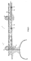
- Fig. 1, 1 denotes a pipeline through which natural gas is conveyed into an oil rig 2 and is guided via a pipeline 3 to another island or platform 4. From there, a further pipeline 5 leads to a distant platform, which is not shown in the drawing. If a leak 6 occurs in the pipeline 5 in the vicinity of the platform 4, the leak will also become after the pipeline 5 has been shut off on the platform 4 from the pressurized, often more than 100 km long pipeline 5 between the platform 4 and the other Platform fed, being in the pipeline 5 a flow to the platform 4 arises between the leak and another platform. Flammable gas escapes, which can endanger the platform 4. In order to limit the outflow, shut-off devices 7 are used in the pipes.
- shut-off device is shown in FIG. 2.
- the upper half of the cut shows the position shown and the lower half of the cut shows the retracted position of the brake sleeve 11 and the sealing device 12.
- An inspection opening at an accessible point of the pipeline in the area of the platform or the oil rig allows the shut-off device to be inserted and removed. If the shut-off device is inserted into the pipeline, the drive wheels 7a are pressed so strongly against the pipe wall that gradients can also be negotiated.
- the shut-off device is positioned at the end of the near area in front of the island or platform 4 (FIG. 1).
- the shut-off device consists - as shown in FIG. 2 - of a hollow cylinder 8, which has sealing points for receiving retracted ends 9a of an annular rubber bellows 9 and clamping bodies 10 designed as rings for fastening the rubber bellows 9.
- the rubber bellows 9 is surrounded by a longitudinally slotted brake sleeve 11 made of metal with a slotted inner collar 11a located at each end.
- the end face located on the side facing the pressure carries a radially adjustable sealing device 12, which closes the annular gap between the pipeline 5 and the hollow cylinder 8.
- a valve seat 8b is arranged on the hollow cylinder 8, to which a valve cone 13a is assigned, which in the open state (lower cutting half) allows the line medium to pass through and blocks in the closed state (upper cutting half).
- the shut-off device 7 After the shut-off device 7 has been introduced into the pipeline 5, it is locked by pressing the brake sleeve 11 against the pipe wall.
- the hollow cylinder 8 has openings 8a which, after pressing the sealing device 12 against the pipe wall, allow the line medium on the pressure side to pass into the space between the rubber bellows 9 and the hollow cylinder 8, while the line medium flows through the hollow cylinder 8.
- the resulting differential pressure causes the rubber bellows 9 and thus the brake sleeve 11 to be pressed against the inner wall of the tube 5, with a holding force being greater than the axial pushing force acting on the shut-off device 7.
- shut-off device When the shut-off device is locked, the line medium can continue to flow through the pipeline 5 in normal operation.
- Means for remote-controlled closing and opening of the valve cone 13a and for automatic closing of the valve cone 13a are provided in the shut-off device 7. If a leak 6 occurs in the vicinity of the platform 4, this is recognized by monitoring devices on the platform and the valve plug 13a can be closed remotely.
- a higher-level automatic closing device integrated in the valve cone 13a enables automatic closing even in the event of malfunctions in the remote control system. This is achieved in that the valve cone 13a reacts to increased flow caused by the leak, as is described in more detail below in relation to FIG. 4.
- the slotted brake sleeve 11 expediently consists of Rigid skid brakes at both ends.
- the angled part of the brake skids including the transition to the skate itself is formed at least on the side facing away from the pressure a bend. Restoring forces are largely avoided as a result.
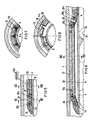
- the brake skids 11c are tangentially overlapped (FIG. 3).
- Retraction elements 11b in the form of an annular spring are assigned to the brake skids. This ring spring prevents the brake sleeve 11 from being released when the shut-off device 7 is installed and removed.
- the rubber bellows 9 is advantageously constructed in several layers, the individual layers x, y, z having different hardnesses. This results in higher wear resistance and greater security against possible mechanical damage.
- radially adjustable sealing device 12 it is expedient to arrange and design the radially adjustable sealing device 12 in such a way that when a predetermined pressure difference occurs between the entry point of the flow medium into the shut-off device and the outlet side of the flow medium from the valve cone 13a, the sealing device 12 is pressed onto the wall of the pipeline in addition to mechanical means becomes.
- Resilient pawls 14 on the outside of the hollow cylinder 8 are assigned to the sealing device 12 on the side b of the hollow cylinder 8 exposed to the pressure, and are pivotably supported there. At their free ends, the pawls 14 have receptacles for fastening the annular sealing device 12, which is designed as a profile seal. The resilient pawls 14 press the sealing device 12 evenly against the pipeline 5 on.
- a frustoconical ring 15 is axially displaceably arranged on the hollow cylinder, which in one position issues the pawls 14 and the sealing device 12 against the spring force of the pawls and the sealing device 12. In the other position of the ring 15, the pawls 14 are released so that the pawls 14 and the sealing device 12 spring back.
- its thickness is less than 1 cm. A thickness of 5 mm is preferred.
- the brake sleeve 11 In order to achieve a small overall length of the shut-off device, it is expedient to provide the brake sleeve 11 with a lining 11d that has a high coefficient of friction.
- the space 16 is connected to the space 17 by longitudinal grooves, pipes or gaps 18 (FIG. 3).
- valve cone 13a The operation of the valve cone 13a is explained in more detail with reference to FIG. 4.
- a hub 20 is arranged via arms 19, in which an adjusting spindle 21 for the valve cone 13 and the drive 22 is mounted.
- two prestressed compression springs 23, 24 with stops 25, 26 are provided, between which the valve cone 13a is mounted so as to be longitudinally displaceable in two directions.
- the valve cone 13a can be brought into the open or closed position under load by means of the drive 22 without the springs 23, 24 changing the pretension.
- valve plug 13a If the valve plug 13a is closed by a motor for the purpose of a test and would remain in this closed position despite actuation of the drive, the valve plug opens at a predetermined pressure of the flow medium against the force of the spring 24 in the direction of arrow A.
- a catch device 27 designed as a catch then holds the valve plug 13a in the open position.
- FIG. 5 shows a detail of a modified holding device of the shut-off device 7 in the retracted position.
- the slotted brake sleeve 11 is connected to the hollow cylinder 8 via arms 28 mounted in joints 28a, 28b. These arms are designed as rockers which, when the brake strips 31 (FIGS. 7 and 8) are applied to the pipeline 5, lie at an acute angle to the pipe axis on the side facing away from the pressure.
- the annular rubber bellows 9 is fastened at both ends by an annular clamping body 10.
- the rubber bellows 9 has radially arranged toroidal beads 29 (see FIGS. 7, 8) which run in the axial direction and which taper to a point at the two ends of the annular rubber bellows or decrease to zero.
- the slotted metal Bresmhülle 11 has in the slots 30 recesses 31a into which the beads 29 protrude and find enough space in the retracted state of the brake sleeve.
- In the issued state take the rubber bellows 9 and the brake sleeve 11 in the position shown in FIG. 6.
- This design has the advantage that the rubber bellows has approximately the same developed length in the circumferential direction both for the applied and for the exposed position. The increase in circumference as a result of the opening movement takes place through a change in shape in the beads 29. This makes it possible to reinforce the rubber bellows 9 tangentially, for example to provide them with fabric or grid inserts, so that a high level of operational safety is achieved. This eliminates overlapping gaps and the freedom of movement of the brake sleeve can be significantly increased.
- the shut-off device which can be inserted into a pipeline 5 has a hollow cylinder 32, on which a valve 13 is arranged, which in the open state is dimensioned for the throughflow of the entire line medium.
- a radially adjustable sealing device 12 is also arranged on the hollow cylinder 32, the outer diameter of which in the retracted position is smaller than the inner pipe diameter. In the issued state of the sealing device 12, the shut-off device is sealed off from the pipeline.
- the sealing device 12 is designed as an annular seal and can be extended by a cylinder spring 37.
- the sealing device 12 has a sleeve which surrounds the cylinder spring 37 and is fastened to the hollow cylinder 32 by a tensioning band 38. Sealing lips 12a are attached to the outside of the sleeve.
- the ends 37a, 37b of the cylinder spring 37 are guided inwards to a fixed point or to a drive 39 designed as an electric motor or hydraulic drive.
- the outer diameter is larger than the inner diameter of the tube 5.
- the two ends 37a, 37b of the cylinder spring 37 are rotated relative to one another, as a result of which the diameter of the cylinder spring 37 and the sealing device 12 is reduced Diameter as the pipe diameter is reduced.
- the direction of rotation of the drive 39 is reversed, the cylinder spring 37 relaxing.
- the sealing device 12 the sleeve of which is made of flexible material, preferably of rubber or plastic, is guided centrally through the perforated disk 41 at its free end.
- the guide surface on the cuff is formed by an annular bead 12b, which is arranged at the free end of the cuff.
- a valve 13 which can be actuated by an electric or hydraulic drive 42, is also arranged on the hollow cylinder 32.
- This drive 42 is accommodated together with the drive 39 in a tubular holder 43, which in turn is attached to the hollow cylinder 32 via arms 44.
- the housing 39a is rigidly connected to the holder 43.
- One end of the hollow cylinder 32 is tapered inward and formed into a valve seat 8b.
- This end of the hollow cylinder 32 also carries a coupling part 34 which can be brought into engagement and sealed with a coupling part 35 attached to a second hollow cylinder 33.
- the coupling is a ball and tube coupling formed in which one or more seals 35a are arranged.
- the second hollow cylinder 33 has the holding device 36, which was used to brake the shut-off device at a predetermined point in the pipeline.
- Pistons 45 are arranged in cylinders 46 in the longitudinal direction of the hollow cylinder 33.
- the line piece within the coupling parts 34, 35 is designed to be coiled.
- Each piston 45 acts on a four-bar linkage, which consists of two parallel pairs of levers 50, 51.
- a base point F1 of the four-bar linkage is rotatably mounted on the piston 45, while the other base point F2 is articulated on the hollow cylinder 33.
- the other ends of the levers are each mounted in a joint C or D of a brake shoe 52.
- a plurality of piston units are arranged one behind the other on the hollow cylinder 33.
- All of the longitudinal pistons 45 lying in series are connected to a retraction rod 53 which is guided centrally through the pistons in such a way that they can move freely in the direction of the braking position and allow the brake shoes 52 different pressing paths (see lower half of the cut).
- the shut-off device is introduced into the pipeline 5 through the pipeline medium during the operation of the pipeline with retracted brake shoes 52, opened valve 13 and retracted sealing device 12, or floated in or brought to a predetermined location in the pipeline by a transport vehicle.
- the sealing device 12 is then actuated by electrical remote control, the annular spring 37 pressing the rubber sleeve against the inner tube wall.
- the force of the spring 37 is advantageously dimensioned such that the sealing device 12, when the valve is open, also acts as a service brake, which holds the shut-off device in the predetermined position as it flows through the line medium.
- Means for the remotely controllable closing and opening of the valve 13 and for the automatic closing of the valve 13 are provided in the shut-off device 7.
- valve 13 can be closed from a central location via a remote control device known per se.
- the resulting pressure difference in the hollow cylinders 32 and 33 becomes Generated the required higher holding force exploited.
- the pistons 45 are acted upon by the high operating pressure via the lines 47, 48, 49 and the brake shoes 52 are pressed against the inner wall of the tube 5. This creates a holding force that is greater than the axial pushing force acting on the shut-off device.
Landscapes
- Engineering & Computer Science (AREA)
- General Engineering & Computer Science (AREA)
- Physics & Mathematics (AREA)
- General Physics & Mathematics (AREA)
- Mechanical Engineering (AREA)
- Pipe Accessories (AREA)
Claims (18)
- Dispositif de barrage (7) mobile dans une conduite tubulaire, pouvant être mis en place dans ladite conduite tubulaire et pouvant être positionné de manière appropriée dans ladite conduite tubulaire (5) au cours du fonctionnement normal de la conduite (5) pendant lequel un courant de fluide s'écoule par la conduite (5), du type dans lequel le dispositif de barrage (7) comprend :a) Un cylindre creux (8),b) Un dispositif d'arrêt prévu sur le cylindre creux (8) pour le freinage du dispositif de barrage (7) en un emplacement pré-déterminé dans la conduite tubulaire (5),c) Une soupape (13) prévue sur le cylindre creux (8) pour le passage du courant de fluide dans la conduite tubulaire (5) et qui est réglable entre une position d'ouverture et une position d'obturation,d) Un organe de retenue (12) réglable radialement et commandé à distance pour l'obturation de l'espace lamellaire (16) entre la paroi de la conduite tubulaire (5) et le cylindre creux (8), dans lequel l'organe de retenue (12) est monté contre le cylindre creux (8) et entre le cylindre creux (8) et la conduite tubulaire (5),e) Un élément pour l'ouverture et la fermeture à distance de la soupape (13), etf) Un organe comprimant l'organe de retenue (12) contre la paroi de la conduite tubulaire (5) à partir d'une différence de pression déterminée entre le coté (a) par lequel le courant de fluide pénètre dans le dispositif de barrage et le coté (b) par lequel le courant de fluide sort du dispositif de barrage (7), caractérisé en ce que la soupape (13) est disposée dans le cylindre creux (8) et dimensionnée pour le passage normal de la totalité du courant de fluide traversant la conduite tubulaire (5) et en ce qu'il est prévu un organe pour la fermeture automatique de la soupape (13) quand la vitesse d'écoulement du courant de fluide dans la conduite tubulaire (5) dépasse une vitesse de fonctionnement normale.
- Dispositif de barrage selon la revendication 1, caractérisé en ce que l'organe de retenue (12) est réuni à un soufflet en caoutchouc (9) de forme annulaire fixé au cylindre creux (8) par un élément de pincement (10), de sorte qu'entre le soufflet en caoutchouc (9) et le cylindre creux (8) est ménagé un espace vide et présente une douille de freinage en métal (11) fendue longitudinalement et disposée par dessus le soufflet de caoutchouc (9).
- Dispositif de barrage selon les revendications 1 ou 2, caractérisé en ce qu'il comporte un bâti de cheminement avec des roues (7a) et un système d'entrainement (7b).
- Dispositif de barrage selon la revendication 2, caractérisé en ce que la douille de freinage fendue (11) est équipée de bandeaux intérieurs (11a), guidé chacun dans une rainure annulaire (8c) du cylindre creux (8) et mobile radialement.
- Dispositif de barrage selon la revendication 4, caractérisé en ce que la douille de freinage fendue (11) présente des patins de freinage (11c).
- Dispositif de barrage selon la revendication 5, caractérisé en ce que les patins de freinages (11c) sont superposés tangentiellement.
- Dispositif de barrage selon les revendications 5 ou 6, caractérisé en ce que, aux patins de freinage (11c) sont associés des éléments de retrait.
- Dispositif de barrage selon l'une des revendications 2 à 5, caractérisé en ce que le soufflet en caoutchouc est formé de plusieurs couches, les couches individuelles (x, y, z) présentant des duretés différentes.
- Dispositif de barrage selon l'une des revendications 2 à 8, caractérisé en ce que l'épaisseur du soufflet en caoutchouc (9) est inférieure à 10 mm, et plus spécialement à 5 mm.
- Dispositif de barrage selon l'une des revendications 2 à 9, caractérisé en ce que la douille de freinage (11) est munie d'une couche (11d) présentant un coefficient de frottement élevé.
- Dispositif de barrage selon l'une des revendications 2 à 10, caractérisé en ce que la douille de freinage (11) présente des cannelures (18) allant de la face (b) à la face (a).
- Dispositif de barrage selon l'une des revendications précédentes, caractérisé en ce que l'organe destiné à la fermeture de la soupape contient un élément qui s'ouvre sous l'effet d'une surpression s'opposant à la direction de fermeture de la soupape (13).
- Dispositif selon l'une des revendications 2 à 12, caractérisé en ce que la douille de freinage fendue (11) est réunie au cylindre creux (8) pardes bras (28) en forme d'ailettes.
- Dispositif de barrage selon la revendication 13, caractérisé en ce que les bras (28) adaptés à la douille de freinage (11) dans la conduite tubulaire font un angle aigu avec l'axe du tube du coté soumis à la pression.
- Dispositif de barrage selon l'une des revendications précédentes, caractérisé en ce que, sur une broche de réglage (21) pour la soupape (13) sont montés deux ressorts de compression précontraints (23, 24) prenant appui sur des butées (25, 26), et entre lesquels la soupape (13) est disposée mobile longitudinalement.
- Dispositif de barrage selon l'une des revendications précédentes, caractérisé en ce qu'il comporte un élément de retenue (27) jouant le rôle d'organe de sécurité, qui maintient la soupape (13) quand elle est amenée en position ouverte par la pression du milieu en circulation à l'encontre de la pression du ressort (24).
- Dispositif de barrage selon l'une des revendications 2 à 16, caractérisé en ce que le soufflet (9) est équipé d'une armature tangentielle en particulier par des inserts en forme de grille ou de tissus.
- Dispositif de barrage selon l'une des revendications précédentes, caractérisé en ce qu'il comporte deux cylindres creux (32, 33) et qu'au moins à une extrémité du premier cylindre creux (32) est monté un organe d'accouplement (34) pouvant s'accrocher et se solidariser avec un organe d'accouplement (35) monté sur le second cylindre creux (33), sur le premier cylindre creux (32) étant montés la soupape (13) et l'organe formant joint (12) réglable radialement, et sur le second cylindre creux (33) étant monté l'organe de retenue (36).
Applications Claiming Priority (4)
| Application Number | Priority Date | Filing Date | Title |
|---|---|---|---|
| DE19863610625 DE3610625A1 (de) | 1986-03-29 | 1986-03-29 | In eine rohrleitung einsetzbare absperrvorrichtung |
| DE3610625 | 1986-03-29 | ||
| DE19863625838 DE3625838A1 (de) | 1986-07-30 | 1986-07-30 | In eine rohrleitung einsetzbare absperrvorrichtung |
| DE3625838 | 1986-07-30 |
Publications (2)
| Publication Number | Publication Date |
|---|---|
| EP0243658A1 EP0243658A1 (fr) | 1987-11-04 |
| EP0243658B1 true EP0243658B1 (fr) | 1992-05-20 |
Family
ID=25842445
Family Applications (1)
| Application Number | Title | Priority Date | Filing Date |
|---|---|---|---|
| EP87104137A Expired - Lifetime EP0243658B1 (fr) | 1986-03-29 | 1987-03-20 | Dispositif d'obturation à placer dans une conduite |
Country Status (8)
| Country | Link |
|---|---|
| US (1) | US4852614A (fr) |
| EP (1) | EP0243658B1 (fr) |
| AU (1) | AU7077787A (fr) |
| BR (1) | BR8701418A (fr) |
| DE (1) | DE3779176D1 (fr) |
| DK (1) | DK157687A (fr) |
| IT (1) | IT1202710B (fr) |
| NO (1) | NO174222C (fr) |
Families Citing this family (12)
| Publication number | Priority date | Publication date | Assignee | Title |
|---|---|---|---|---|
| DE3610624A1 (de) * | 1986-03-29 | 1987-10-08 | Norske Stats Oljeselskap | Vorrichtung zum verschliessen einer rohrleitung |
| GB8800671D0 (en) * | 1988-01-13 | 1988-02-10 | Forsac Ltd | Displaceable valve assembly |
| SE462930B (sv) * | 1988-03-02 | 1990-09-17 | Rintuv Utvecklings Ab | Anordning vid relining av roerledningar med tryckmediumpaaverkbara griporgan |
| WO1989012196A1 (fr) * | 1988-06-01 | 1989-12-14 | Siemens Aktiengesellschaft | Dispositif de commande pour actionner une vanne et un systeme d'etancheite |
| WO1989012197A1 (fr) * | 1988-06-01 | 1989-12-14 | Siemens Aktiengesellschaft | Dispositif de rearmement pour demontage d'un systeme d'etancheite a commande hydraulique |
| GB8825851D0 (en) * | 1988-11-04 | 1988-12-07 | Sneddon J L | Temporary plugs for pipelines |
| US5293905A (en) * | 1992-08-21 | 1994-03-15 | Jaromir Friedrich | Pipeline plug |
| CA2237257A1 (fr) * | 1998-05-08 | 1999-11-08 | Pa - Plug Inc. | Bouchon aval |
| DE19909634C2 (de) * | 1999-03-05 | 2002-02-07 | Willschuetz Klaus Dieter | Pipelinereparatur-Hilfsvorrichtung |
| FR3016952B1 (fr) | 2014-01-28 | 2016-09-09 | Gdf Suez | Outil pour intervention sur la paroi d'une canalisation - methode associee. |
| US10578239B2 (en) | 2016-02-16 | 2020-03-03 | Cherne Industries Incorporated | High pressure test plug |
| RU181250U1 (ru) * | 2017-11-07 | 2018-07-06 | Публичное акционерное общество "Транснефть" (ПАО "Транснефть") | Устройство для герметизации внутренней полости магистрального трубопровода |
Family Cites Families (21)
| Publication number | Priority date | Publication date | Assignee | Title |
|---|---|---|---|---|
| US2439117A (en) * | 1942-04-11 | 1948-04-06 | Waterman William | Automatic cutoff |
| US2786489A (en) * | 1954-09-16 | 1957-03-26 | Mid Valley Pipeline Company | Pipe line plugs |
| US2926690A (en) * | 1957-11-04 | 1960-03-01 | James D Martin | Pressure responsive flow-stop valve |
| US3107696A (en) * | 1960-05-02 | 1963-10-22 | Williamson Inc T | Plugging pig |
| US3381714A (en) * | 1965-06-29 | 1968-05-07 | Marathon Oil Co | Pipeline blocking device and process for its use |
| US3495626A (en) * | 1967-10-18 | 1970-02-17 | American Mach & Foundry | Pipeline plugging apparatus and methods |
| US3543852A (en) * | 1968-12-16 | 1970-12-01 | Otis Eng Corp | Well tools |
| US3683957A (en) * | 1970-09-29 | 1972-08-15 | Asa D Sands | Safety valve |
| US4077435A (en) * | 1973-09-14 | 1978-03-07 | Willard A. Sawyer | Pipeline plugging apparatus |
| CA1016086A (en) * | 1973-09-14 | 1977-08-23 | Davis A. Van Scoy | Pipeline plugging apparatus and method |
| US4026329A (en) * | 1973-12-26 | 1977-05-31 | Texas Pipe Line Company | Method and apparatus for remotely and releasably sealing a pipeline |
| US3895652A (en) * | 1974-01-11 | 1975-07-22 | Roger G Zach | Diametrically expansible coil spring conduit plug |
| US3978678A (en) * | 1975-10-14 | 1976-09-07 | Hydrotech International, Inc. | Method and apparatus for plugging a pipeline |
| GB1554894A (en) * | 1977-11-28 | 1979-10-31 | Pilgrim Eng Dev | Pipeline pigs |
| US4458721A (en) * | 1979-02-28 | 1984-07-10 | Brooklyn Union Gas Company | Pipeline flow restrictor |
| US4332277A (en) * | 1980-09-03 | 1982-06-01 | Hughes Undersea Coupling, Inc. | Pipeline pigging plug |
| NL178188C (nl) * | 1980-10-29 | 1986-02-03 | Petroles Cie Francaise | Afsluiter. |
| US4422477A (en) * | 1981-02-27 | 1983-12-27 | Hughes Tool Company | Pressure energized pipeline plug |
| US4413653A (en) * | 1981-10-08 | 1983-11-08 | Halliburton Company | Inflation anchor |
| US4423754A (en) * | 1982-02-22 | 1984-01-03 | Halliburton Company | Cup type pipeline inflation anchor |
| US4605039A (en) * | 1984-10-04 | 1986-08-12 | Stewart-Warner Corporation | Runaway protective fuse valve |
-
1987
- 1987-03-20 DE DE8787104137T patent/DE3779176D1/de not_active Expired - Fee Related
- 1987-03-20 NO NO871147A patent/NO174222C/no not_active IP Right Cessation
- 1987-03-20 EP EP87104137A patent/EP0243658B1/fr not_active Expired - Lifetime
- 1987-03-27 BR BR8701418A patent/BR8701418A/pt unknown
- 1987-03-27 US US07/031,404 patent/US4852614A/en not_active Expired - Fee Related
- 1987-03-27 DK DK157687A patent/DK157687A/da not_active Application Discontinuation
- 1987-03-27 IT IT8719872A patent/IT1202710B/it active
- 1987-03-30 AU AU70777/87A patent/AU7077787A/en not_active Abandoned
Also Published As
| Publication number | Publication date |
|---|---|
| IT8719872A0 (it) | 1987-03-27 |
| US4852614A (en) | 1989-08-01 |
| DE3779176D1 (de) | 1992-07-02 |
| AU7077787A (en) | 1987-10-01 |
| DK157687D0 (da) | 1987-03-27 |
| DK157687A (da) | 1987-09-30 |
| IT1202710B (it) | 1989-02-09 |
| EP0243658A1 (fr) | 1987-11-04 |
| BR8701418A (pt) | 1988-01-05 |
| NO871147L (no) | 1987-09-30 |
| NO174222C (no) | 1994-03-30 |
| NO871147D0 (no) | 1987-03-20 |
| NO174222B (no) | 1993-12-20 |
Similar Documents
| Publication | Publication Date | Title |
|---|---|---|
| DE2402070C2 (de) | Prüfgerät zum Untersuchen der Ergiebigkeit einer von einem Bohrloch durchsetzten, ölführenden Erdformation | |
| EP0243658B1 (fr) | Dispositif d'obturation à placer dans une conduite | |
| DE2455934A1 (de) | Stuetz- und ausrichtanordnung, insbesondere fuer rohrverschweissungen | |
| EP0418507B2 (fr) | Dispositif de freinage et/ou de serrage | |
| DE2505318C2 (de) | Zusammenlegbare Reifenfertigungstrommel | |
| DE2946811A1 (de) | Bremskraftverstaerker | |
| DE60013961T2 (de) | Universelle Sicherheitsvorrichtung und Verfahren zum Schützen einer Rohrleitung | |
| DE2630383A1 (de) | Vorrichtung zum formen von material durch extrusion | |
| DE3121893C2 (fr) | ||
| DE3307813C1 (de) | Werkzeug zur Pruefung von Rohren in einer Rohrpruefpresse | |
| DE1299266B (de) | Dehnbare Sprengvorrichtung fuer den Bergbau | |
| DE2551126A1 (de) | Hydropneumatischer ventilantrieb | |
| EP0240851A2 (fr) | Dispositif d'obturation d'une tuyauterie | |
| EP0457030B1 (fr) | Cylindre de frein à ressort pour freins actionnés par moyen de pression pour véhicules routiers | |
| DE3610625A1 (de) | In eine rohrleitung einsetzbare absperrvorrichtung | |
| DE3625838A1 (de) | In eine rohrleitung einsetzbare absperrvorrichtung | |
| DE2345331C2 (de) | Verschlußvorrichtung für Rohrleitungen, insbesondere Pipelines | |
| DE3333004A1 (de) | Vorrichtung zum verdichten von koernigen formstoffen | |
| DE102019113382A1 (de) | Dichtungselement für einen Rohrleitungsmolch | |
| DE3818703A1 (de) | Ausstellvorrichtung fuer eine in rohrleitungen einfahrbare rohrabsperrvorrichtung | |
| DE3811442C1 (fr) | ||
| DE2620905C3 (de) | Ringschieber | |
| DE3243905C2 (de) | Ventilkupplung für Fluidleitungen | |
| DE19638778B4 (de) | Vorrichtung zum Absperren einer fluidführenden Rohrleitung | |
| DE2325879B1 (de) | Befestigungsflansch aus Gummi an Gummischläuchen |
Legal Events
| Date | Code | Title | Description |
|---|---|---|---|
| PUAI | Public reference made under article 153(3) epc to a published international application that has entered the european phase |
Free format text: ORIGINAL CODE: 0009012 |
|
| AK | Designated contracting states |
Kind code of ref document: A1 Designated state(s): BE DE FR GB NL SE |
|
| 17P | Request for examination filed |
Effective date: 19880414 |
|
| 17Q | First examination report despatched |
Effective date: 19890518 |
|
| GRAA | (expected) grant |
Free format text: ORIGINAL CODE: 0009210 |
|
| AK | Designated contracting states |
Kind code of ref document: B1 Designated state(s): BE DE FR GB NL SE |
|
| PG25 | Lapsed in a contracting state [announced via postgrant information from national office to epo] |
Ref country code: SE Effective date: 19920520 Ref country code: BE Effective date: 19920520 |
|
| REF | Corresponds to: |
Ref document number: 3779176 Country of ref document: DE Date of ref document: 19920702 |
|
| ET | Fr: translation filed | ||
| GBT | Gb: translation of ep patent filed (gb section 77(6)(a)/1977) | ||
| PGFP | Annual fee paid to national office [announced via postgrant information from national office to epo] |
Ref country code: DE Payment date: 19930324 Year of fee payment: 7 |
|
| PLBE | No opposition filed within time limit |
Free format text: ORIGINAL CODE: 0009261 |
|
| STAA | Information on the status of an ep patent application or granted ep patent |
Free format text: STATUS: NO OPPOSITION FILED WITHIN TIME LIMIT |
|
| 26N | No opposition filed | ||
| PG25 | Lapsed in a contracting state [announced via postgrant information from national office to epo] |
Ref country code: DE Effective date: 19941201 |
|
| PGFP | Annual fee paid to national office [announced via postgrant information from national office to epo] |
Ref country code: NL Payment date: 19950331 Year of fee payment: 9 |
|
| PGFP | Annual fee paid to national office [announced via postgrant information from national office to epo] |
Ref country code: FR Payment date: 19960126 Year of fee payment: 10 |
|
| PG25 | Lapsed in a contracting state [announced via postgrant information from national office to epo] |
Ref country code: NL Effective date: 19961001 |
|
| NLV4 | Nl: lapsed or anulled due to non-payment of the annual fee |
Effective date: 19961001 |
|
| PG25 | Lapsed in a contracting state [announced via postgrant information from national office to epo] |
Ref country code: FR Free format text: LAPSE BECAUSE OF NON-PAYMENT OF DUE FEES Effective date: 19971128 |
|
| REG | Reference to a national code |
Ref country code: FR Ref legal event code: ST |
|
| REG | Reference to a national code |
Ref country code: GB Ref legal event code: IF02 |
|
| PGFP | Annual fee paid to national office [announced via postgrant information from national office to epo] |
Ref country code: GB Payment date: 20020320 Year of fee payment: 16 |
|
| PG25 | Lapsed in a contracting state [announced via postgrant information from national office to epo] |
Ref country code: GB Free format text: LAPSE BECAUSE OF NON-PAYMENT OF DUE FEES Effective date: 20030320 |
|
| GBPC | Gb: european patent ceased through non-payment of renewal fee |
Effective date: 20030320 |