EP0243658B1 - Pipeline plugging apparatus - Google Patents
Pipeline plugging apparatus Download PDFInfo
- Publication number
- EP0243658B1 EP0243658B1 EP87104137A EP87104137A EP0243658B1 EP 0243658 B1 EP0243658 B1 EP 0243658B1 EP 87104137 A EP87104137 A EP 87104137A EP 87104137 A EP87104137 A EP 87104137A EP 0243658 B1 EP0243658 B1 EP 0243658B1
- Authority
- EP
- European Patent Office
- Prior art keywords
- shut
- pipeline
- hollow cylinder
- valve
- appliance according
- Prior art date
- Legal status (The legal status is an assumption and is not a legal conclusion. Google has not performed a legal analysis and makes no representation as to the accuracy of the status listed.)
- Expired - Lifetime
Links
Images


Classifications
-
- F—MECHANICAL ENGINEERING; LIGHTING; HEATING; WEAPONS; BLASTING
- F16—ENGINEERING ELEMENTS AND UNITS; GENERAL MEASURES FOR PRODUCING AND MAINTAINING EFFECTIVE FUNCTIONING OF MACHINES OR INSTALLATIONS; THERMAL INSULATION IN GENERAL
- F16L—PIPES; JOINTS OR FITTINGS FOR PIPES; SUPPORTS FOR PIPES, CABLES OR PROTECTIVE TUBING; MEANS FOR THERMAL INSULATION IN GENERAL
- F16L55/00—Devices or appurtenances for use in, or in connection with, pipes or pipe systems
- F16L55/10—Means for stopping flow from or in pipes or hoses
- F16L55/12—Means for stopping flow from or in pipes or hoses by introducing into the pipe a member expandable in situ
- F16L55/128—Means for stopping flow from or in pipes or hoses by introducing into the pipe a member expandable in situ introduced axially into the pipe or hose
- F16L55/1283—Plugging pig
-
- G—PHYSICS
- G01—MEASURING; TESTING
- G01M—TESTING STATIC OR DYNAMIC BALANCE OF MACHINES OR STRUCTURES; TESTING OF STRUCTURES OR APPARATUS, NOT OTHERWISE PROVIDED FOR
- G01M3/00—Investigating fluid-tightness of structures
- G01M3/005—Investigating fluid-tightness of structures using pigs or moles
Definitions
- shut-off device is known from US-A-34 95 626.
- the hollow cylinder has a passage cross-section which is small compared to the passage cross section of the pipeline, so that the flow through the shut-off device is impaired in comparison to the normal flow through the pipeline.
- this known shut-off device is only intended to be used in a pipeline only when the pipeline is in need of repair, i.e. if, for example, a leaky pipe section has to be removed from the pipeline and replaced with a new, tight pipe section.
- a shut-off device of the type mentioned above is also known from GB-A-14 52 232.
- the hollow cylinder is closed on its front side, ie on its downstream side, with an end element, so that the flow through the hollow cylinder is at least impaired or interrupted by the valve adjustable between an open and a closed position.
- the valve adjustable between an open and a closed position Through this valve, the flow through the hollow cylinder is interrupted until the shut-off device on stop devices to the system comes that stretch into the pipeline.
- the anchor devices involve a not insignificant amount of work both in their manufacture and in their assembly on the pipeline.
- This known shut-off device is also only intended to be introduced into a pipeline only when the pipeline is in need of repair.
- US-A-44 13 653 discloses a device which is provided for fixing in a pipeline and which for this purpose has a hollow cylinder and a holding device provided on the hollow cylinder for braking the device at a predetermined point in the pipeline.
- This device has an annular or tubular rubber bellows with retracted ends which are fixed to the hollow cylinder by means of suitable clamping bodies. In this way, the space between the hollow cylinder and the rubber bellows is sealed or a medium can be introduced into the cavity in order to expand the rubber bellows and thereby fix the device in the pipeline at a desired location.
- a pipe closure device is known from EP-A-0 087 867, which can be inserted into a pipe after a leak has occurred or for test purposes.
- This pipe closure device consists of two bodies which can be coupled to one another, one of which is designed in the manner of an elastic stopper, which has sealing lips on its circumference, the diameter of which corresponds to the inside diameter of the pipe.
- the second body is used for anchoring and is designed in the manner of a pot, which is formed from a metal base and a radially expandable jacket made of elastic material connected to it.
- the coat consists of a metal base
- the adjacent area consists of several elastic plastic layers with metal-reinforced inlays that form the actual anchoring part.
- a non-return valve is arranged on the metal base, which can be brought into the open or closed position by remote control via an electronic device.
- the pipe closure device After the pipe closure device has been inserted into the pipeline, it is pumped to a predetermined point with the valve open.
- the open valve compensates for pressure, so that the pipeline medium flows around the jacket and it cannot lie against the pipe wall during transport.
- the valve To anchor the pipe closure device, the valve is closed remotely by an electromagnetic signal and the pipeline medium is pressurized, whereby the jacket of the anchoring part is pressed against the pipe wall and held in place by frictional engagement.
- the valve To release the anchoring, the valve is opened again, the elastic jacket contracting again due to the pressure compensation and being lifted off the inner surface of the pipeline.
- shut-off device consists of a cylindrical body which is surrounded by an inflatable rubber sleeve and carries an annular seal on each of the two end faces.
- the shut-off device is inserted into the pipeline on a platform and washed through the pipeline in the manner of a piston.
- the closure device is locked in the pipeline near the leak.
- pressurized gas bottles which are arranged within the cylindrical body, are opened by remote ignition, so that gas is introduced into the rubber bladder, which presses an outer sleeve against the tube wall, and in this way brakes the closure device in the pipeline. As a result, no further medium reaches the leak.
- the known closure devices are therefore only in the event of a fault, i.e. if e.g. a leak in a pipeline occurs, washed like a piston through the pipeline and brought to a predetermined location.
- the use of such closure devices takes a considerable amount of time before they are brought close to the leak in the event of a leak.
- the invention has for its object to provide a movable in a pipeline shut-off device of the type mentioned, which can be permanently in the pipeline without affecting the flow of medium in the pipeline, and which immediately if a leak occurs in the pipeline, i.e. can be started without delay.
- valve is arranged in the hollow cylinder and is dimensioned for the normal passage of the entire flow medium flowing through the pipeline, and in that a device is provided for automatically closing the valve when the flow velocity of the fluid in the pipeline is at its normal operating speed exceeds.
- the closure device according to the invention can be inserted into the pipeline before a leak occurs during operation and connected to a pipe anchored in a safety-relevant, predetermined place.
- a valve cone and a radially adjustable sealing device arranged between the tube wall and the hollow cylinder are preferably provided in the hollow cylinder, the pressure difference of the fluid which arises when the valve cone is open being used to form holding forces of the holding device in normal operation and the increased pressure difference which arises when the valve cone is closed for generating the required higher retention force is used.
- This design has the advantage that pressure accumulators for loading the brake sleeve can be dispensed with and the holding forces only significantly load the tube wall when the valve cone is closed.
- the hollow cylinder of the shut-off device is preferably dimensionally stable and has sealing points for receiving the retracted ends of an annular rubber bellows and clamping bodies for fastening the rubber bellows, which is surrounded by a longitudinally slotted brake sleeve made of metal, which is connected to the hollow cylinder on the side facing away from the pressure, which is flowed through by the line medium and on the side facing the pressure carries the radially adjustable sealing device which closes off the annular space between the pipeline and the hollow cylinder, the valve cone permitting the line medium to pass through and shut off in the closed state.
- the valve cone when the valve cone is closed, they overlap on the pipe wall acting holding forces with the forces from full gas pressure, since they act on the low pressure side, so that the pipe wall is not overstressed.
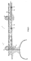
- Fig. 1, 1 denotes a pipeline through which natural gas is conveyed into an oil rig 2 and is guided via a pipeline 3 to another island or platform 4. From there, a further pipeline 5 leads to a distant platform, which is not shown in the drawing. If a leak 6 occurs in the pipeline 5 in the vicinity of the platform 4, the leak will also become after the pipeline 5 has been shut off on the platform 4 from the pressurized, often more than 100 km long pipeline 5 between the platform 4 and the other Platform fed, being in the pipeline 5 a flow to the platform 4 arises between the leak and another platform. Flammable gas escapes, which can endanger the platform 4. In order to limit the outflow, shut-off devices 7 are used in the pipes.
- shut-off device is shown in FIG. 2.
- the upper half of the cut shows the position shown and the lower half of the cut shows the retracted position of the brake sleeve 11 and the sealing device 12.
- An inspection opening at an accessible point of the pipeline in the area of the platform or the oil rig allows the shut-off device to be inserted and removed. If the shut-off device is inserted into the pipeline, the drive wheels 7a are pressed so strongly against the pipe wall that gradients can also be negotiated.
- the shut-off device is positioned at the end of the near area in front of the island or platform 4 (FIG. 1).
- the shut-off device consists - as shown in FIG. 2 - of a hollow cylinder 8, which has sealing points for receiving retracted ends 9a of an annular rubber bellows 9 and clamping bodies 10 designed as rings for fastening the rubber bellows 9.
- the rubber bellows 9 is surrounded by a longitudinally slotted brake sleeve 11 made of metal with a slotted inner collar 11a located at each end.
- the end face located on the side facing the pressure carries a radially adjustable sealing device 12, which closes the annular gap between the pipeline 5 and the hollow cylinder 8.
- a valve seat 8b is arranged on the hollow cylinder 8, to which a valve cone 13a is assigned, which in the open state (lower cutting half) allows the line medium to pass through and blocks in the closed state (upper cutting half).
- the shut-off device 7 After the shut-off device 7 has been introduced into the pipeline 5, it is locked by pressing the brake sleeve 11 against the pipe wall.
- the hollow cylinder 8 has openings 8a which, after pressing the sealing device 12 against the pipe wall, allow the line medium on the pressure side to pass into the space between the rubber bellows 9 and the hollow cylinder 8, while the line medium flows through the hollow cylinder 8.
- the resulting differential pressure causes the rubber bellows 9 and thus the brake sleeve 11 to be pressed against the inner wall of the tube 5, with a holding force being greater than the axial pushing force acting on the shut-off device 7.
- shut-off device When the shut-off device is locked, the line medium can continue to flow through the pipeline 5 in normal operation.
- Means for remote-controlled closing and opening of the valve cone 13a and for automatic closing of the valve cone 13a are provided in the shut-off device 7. If a leak 6 occurs in the vicinity of the platform 4, this is recognized by monitoring devices on the platform and the valve plug 13a can be closed remotely.
- a higher-level automatic closing device integrated in the valve cone 13a enables automatic closing even in the event of malfunctions in the remote control system. This is achieved in that the valve cone 13a reacts to increased flow caused by the leak, as is described in more detail below in relation to FIG. 4.
- the slotted brake sleeve 11 expediently consists of Rigid skid brakes at both ends.
- the angled part of the brake skids including the transition to the skate itself is formed at least on the side facing away from the pressure a bend. Restoring forces are largely avoided as a result.
- the brake skids 11c are tangentially overlapped (FIG. 3).
- Retraction elements 11b in the form of an annular spring are assigned to the brake skids. This ring spring prevents the brake sleeve 11 from being released when the shut-off device 7 is installed and removed.
- the rubber bellows 9 is advantageously constructed in several layers, the individual layers x, y, z having different hardnesses. This results in higher wear resistance and greater security against possible mechanical damage.
- radially adjustable sealing device 12 it is expedient to arrange and design the radially adjustable sealing device 12 in such a way that when a predetermined pressure difference occurs between the entry point of the flow medium into the shut-off device and the outlet side of the flow medium from the valve cone 13a, the sealing device 12 is pressed onto the wall of the pipeline in addition to mechanical means becomes.
- Resilient pawls 14 on the outside of the hollow cylinder 8 are assigned to the sealing device 12 on the side b of the hollow cylinder 8 exposed to the pressure, and are pivotably supported there. At their free ends, the pawls 14 have receptacles for fastening the annular sealing device 12, which is designed as a profile seal. The resilient pawls 14 press the sealing device 12 evenly against the pipeline 5 on.
- a frustoconical ring 15 is axially displaceably arranged on the hollow cylinder, which in one position issues the pawls 14 and the sealing device 12 against the spring force of the pawls and the sealing device 12. In the other position of the ring 15, the pawls 14 are released so that the pawls 14 and the sealing device 12 spring back.
- its thickness is less than 1 cm. A thickness of 5 mm is preferred.
- the brake sleeve 11 In order to achieve a small overall length of the shut-off device, it is expedient to provide the brake sleeve 11 with a lining 11d that has a high coefficient of friction.
- the space 16 is connected to the space 17 by longitudinal grooves, pipes or gaps 18 (FIG. 3).
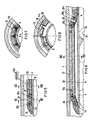
- valve cone 13a The operation of the valve cone 13a is explained in more detail with reference to FIG. 4.
- a hub 20 is arranged via arms 19, in which an adjusting spindle 21 for the valve cone 13 and the drive 22 is mounted.
- two prestressed compression springs 23, 24 with stops 25, 26 are provided, between which the valve cone 13a is mounted so as to be longitudinally displaceable in two directions.
- the valve cone 13a can be brought into the open or closed position under load by means of the drive 22 without the springs 23, 24 changing the pretension.
- valve plug 13a If the valve plug 13a is closed by a motor for the purpose of a test and would remain in this closed position despite actuation of the drive, the valve plug opens at a predetermined pressure of the flow medium against the force of the spring 24 in the direction of arrow A.
- a catch device 27 designed as a catch then holds the valve plug 13a in the open position.
- FIG. 5 shows a detail of a modified holding device of the shut-off device 7 in the retracted position.
- the slotted brake sleeve 11 is connected to the hollow cylinder 8 via arms 28 mounted in joints 28a, 28b. These arms are designed as rockers which, when the brake strips 31 (FIGS. 7 and 8) are applied to the pipeline 5, lie at an acute angle to the pipe axis on the side facing away from the pressure.
- the annular rubber bellows 9 is fastened at both ends by an annular clamping body 10.
- the rubber bellows 9 has radially arranged toroidal beads 29 (see FIGS. 7, 8) which run in the axial direction and which taper to a point at the two ends of the annular rubber bellows or decrease to zero.
- the slotted metal Bresmhülle 11 has in the slots 30 recesses 31a into which the beads 29 protrude and find enough space in the retracted state of the brake sleeve.
- In the issued state take the rubber bellows 9 and the brake sleeve 11 in the position shown in FIG. 6.
- This design has the advantage that the rubber bellows has approximately the same developed length in the circumferential direction both for the applied and for the exposed position. The increase in circumference as a result of the opening movement takes place through a change in shape in the beads 29. This makes it possible to reinforce the rubber bellows 9 tangentially, for example to provide them with fabric or grid inserts, so that a high level of operational safety is achieved. This eliminates overlapping gaps and the freedom of movement of the brake sleeve can be significantly increased.
- the shut-off device which can be inserted into a pipeline 5 has a hollow cylinder 32, on which a valve 13 is arranged, which in the open state is dimensioned for the throughflow of the entire line medium.
- a radially adjustable sealing device 12 is also arranged on the hollow cylinder 32, the outer diameter of which in the retracted position is smaller than the inner pipe diameter. In the issued state of the sealing device 12, the shut-off device is sealed off from the pipeline.
- the sealing device 12 is designed as an annular seal and can be extended by a cylinder spring 37.
- the sealing device 12 has a sleeve which surrounds the cylinder spring 37 and is fastened to the hollow cylinder 32 by a tensioning band 38. Sealing lips 12a are attached to the outside of the sleeve.
- the ends 37a, 37b of the cylinder spring 37 are guided inwards to a fixed point or to a drive 39 designed as an electric motor or hydraulic drive.
- the outer diameter is larger than the inner diameter of the tube 5.
- the two ends 37a, 37b of the cylinder spring 37 are rotated relative to one another, as a result of which the diameter of the cylinder spring 37 and the sealing device 12 is reduced Diameter as the pipe diameter is reduced.
- the direction of rotation of the drive 39 is reversed, the cylinder spring 37 relaxing.
- the sealing device 12 the sleeve of which is made of flexible material, preferably of rubber or plastic, is guided centrally through the perforated disk 41 at its free end.
- the guide surface on the cuff is formed by an annular bead 12b, which is arranged at the free end of the cuff.
- a valve 13 which can be actuated by an electric or hydraulic drive 42, is also arranged on the hollow cylinder 32.
- This drive 42 is accommodated together with the drive 39 in a tubular holder 43, which in turn is attached to the hollow cylinder 32 via arms 44.
- the housing 39a is rigidly connected to the holder 43.
- One end of the hollow cylinder 32 is tapered inward and formed into a valve seat 8b.
- This end of the hollow cylinder 32 also carries a coupling part 34 which can be brought into engagement and sealed with a coupling part 35 attached to a second hollow cylinder 33.
- the coupling is a ball and tube coupling formed in which one or more seals 35a are arranged.
- the second hollow cylinder 33 has the holding device 36, which was used to brake the shut-off device at a predetermined point in the pipeline.
- Pistons 45 are arranged in cylinders 46 in the longitudinal direction of the hollow cylinder 33.
- the line piece within the coupling parts 34, 35 is designed to be coiled.
- Each piston 45 acts on a four-bar linkage, which consists of two parallel pairs of levers 50, 51.
- a base point F1 of the four-bar linkage is rotatably mounted on the piston 45, while the other base point F2 is articulated on the hollow cylinder 33.
- the other ends of the levers are each mounted in a joint C or D of a brake shoe 52.
- a plurality of piston units are arranged one behind the other on the hollow cylinder 33.
- All of the longitudinal pistons 45 lying in series are connected to a retraction rod 53 which is guided centrally through the pistons in such a way that they can move freely in the direction of the braking position and allow the brake shoes 52 different pressing paths (see lower half of the cut).
- the shut-off device is introduced into the pipeline 5 through the pipeline medium during the operation of the pipeline with retracted brake shoes 52, opened valve 13 and retracted sealing device 12, or floated in or brought to a predetermined location in the pipeline by a transport vehicle.
- the sealing device 12 is then actuated by electrical remote control, the annular spring 37 pressing the rubber sleeve against the inner tube wall.
- the force of the spring 37 is advantageously dimensioned such that the sealing device 12, when the valve is open, also acts as a service brake, which holds the shut-off device in the predetermined position as it flows through the line medium.
- Means for the remotely controllable closing and opening of the valve 13 and for the automatic closing of the valve 13 are provided in the shut-off device 7.
- valve 13 can be closed from a central location via a remote control device known per se.
- the resulting pressure difference in the hollow cylinders 32 and 33 becomes Generated the required higher holding force exploited.
- the pistons 45 are acted upon by the high operating pressure via the lines 47, 48, 49 and the brake shoes 52 are pressed against the inner wall of the tube 5. This creates a holding force that is greater than the axial pushing force acting on the shut-off device.
Description
Die Erfindung bezieht sich auf eine in einer Rohrleitung bewegbare Absperrvorrichtung, die in die Rohrleitung einsetzbar und in der Rohrleitung während des normalen Betriebes der Rohrleitung, während welchem ein Strömungsmedium durch die Rohrleitung strömt, geeignet positionierbar ist, wobei die Absperrvorrichtung
- a) einen Hohlzylinder
- b) eine am Hohlzylinder vorgesehene Halteeinrichtung zum Festbremsen der Absperrvorrichtung an einer vorgegebenen Stelle in der Rohrleitung,
- c) ein zum Durchlass des Strömungsmediums durch die Rohrleitung am Hohlzylinder vorgesehenes Ventil, das zwischen einer Öffnungs- und einer Verschlußstellung verstellbar ist,
- d) eine fernsteuerbare, radial verstellbare Dichteinrichtung zum Abdichten des zwischen der Wandung der Rohrleitung und dem Hohlzylinder gegebenen Spaltraums, an dem die Dichteinrichtung am Hohlzylinder angebracht und zwischen dem Hohlzylinder und der Wandung der Rohrleitung angeordnet ist,
- e) eine Einrichtung zum ferngesteuerten Verschliessen und Öffnen des Ventils, und
- f) eine Einrichtung zum Pressen der Dichteinrichtung gegen die Wandung der Rohrleitung ab einer bestimmten Druckdifferenz zwischen der Seite, an welcher das Strömungsmittel in die Absperrvorrichtung eintritt, und der Seite, an welcher das Strömungsmittel aus der Absperrvorrichtung austritt,
- a) a hollow cylinder
- b) a holding device provided on the hollow cylinder for braking the shut-off device at a predetermined location in the pipeline,
- c) a valve provided on the hollow cylinder for the passage of the flow medium through the pipeline and which is adjustable between an open and a closed position,
- d) a remotely controllable, radially adjustable sealing device for sealing the gap between the wall of the pipeline and the hollow cylinder, to which the sealing device is attached to the hollow cylinder and arranged between the hollow cylinder and the wall of the pipeline,
- (e) means for remotely closing and opening the valve; and
- f) a device for pressing the sealing device against the wall of the pipeline from a certain pressure difference between the side on which the fluid enters the shut-off device and the side on which the fluid exits the shut-off device,
Eine derartige Absperrvorrichtung ist aus der US-A-34 95 626 bekannt. Bei dieser bekannten Absperrvorrichtung weist der Hohlzylinder einen im Vergleich zum Durchlassquerschnitt der Rohrleitung kleinen Durchlassquerschnitt auf, so dass die Strömung durch die Absperrvorrichtung hindurch im Vergleich zur normalen Strömung durch die Rohrleitung hindurch beeinträchtigt ist. Aus diesem Grunde ist diese bekannte Absperrvorrichtung auch nur dazu vorgesehen, erst dann in eine Rohrleitung eingesetzt zu werden, wenn die Rohrleitung reparaturbedürftig ist, d.h. wenn bspw. ein undichtes Rohrstück aus der Rohrleitung entfernt und durch ein neues, dichtes Rohrstück ersetzt werden muss.Such a shut-off device is known from US-A-34 95 626. In this known shut-off device, the hollow cylinder has a passage cross-section which is small compared to the passage cross section of the pipeline, so that the flow through the shut-off device is impaired in comparison to the normal flow through the pipeline. For this reason, this known shut-off device is only intended to be used in a pipeline only when the pipeline is in need of repair, i.e. if, for example, a leaky pipe section has to be removed from the pipeline and replaced with a new, tight pipe section.
Eine Absperrvorrichtung der oben genannten Art ist auch aus der GB-A-14 52 232 bekannt. Dort ist der Hohlzylinder an seiner Vorderseite, d.h. an seiner stromabwärtigen Seite, mit einem Stirnelement abgeschlossen, so dass die Durchströmung des Hohlzylinders zumindest beeinträchtigt bzw. durch das zwischen einer Öffnungs- und einer Verschlußstellung verstellbare Ventil unterbrochen ist. Durch dieses Ventil ist der Durchfluss durch den Hohlzylinder so lange unterbrochen, bis die Absperrvorrichtung an Anschlageinrichtungen zur Anlage kommt, die sich in die Rohrleitung hineinerstrecken. Die Anschlageinrichtungen bedingen einen nicht zu vernachlässigenden Arbeitsaufwand sowohl bei ihrer Herstellung als auch bei ihrer Montage an der Rohrleitung. Diese bekannte Absperrvorrichtung ist ebenfalls nur dazu vorgesehen, erst dann in eine Rohrleitung eingebracht zu werden, wenn die Rohrleitung reparaturbedürftig ist.A shut-off device of the type mentioned above is also known from GB-A-14 52 232. There, the hollow cylinder is closed on its front side, ie on its downstream side, with an end element, so that the flow through the hollow cylinder is at least impaired or interrupted by the valve adjustable between an open and a closed position. Through this valve, the flow through the hollow cylinder is interrupted until the shut-off device on stop devices to the system comes that stretch into the pipeline. The anchor devices involve a not insignificant amount of work both in their manufacture and in their assembly on the pipeline. This known shut-off device is also only intended to be introduced into a pipeline only when the pipeline is in need of repair.
Die US-A-44 13 653 offenbart eine Vorrichtung, die zur Fixierung in einer Rohrleitung vorgesehen ist und die zu diesem Zweck einen Hohlzylinder und eine am Hohlzylinder vorgesehene Halteeinrichtung zum Festbremsen der Vorrichtung an einer vorgegebenen Stelle in der Rohrleitung aufweist. Diese Vorrichtung besitzt einen ring- bzw. rohrförmigen Gummibalg mit eingezogenen Enden, die mittels geeigneter Klemmkörper am Hohlzylinder festgelegt sind. Auf diese Weise ist der Raum zwischen dem Hohlzylinder und dem Gummibalg abgedichtet bzw. in den Hohlraum ein Medium einleitbar, um den Gummibalg aufzuweiten und hierdurch die Vorrichtung in der Rohrleitung an einem gewünschten Ort zu fixieren.US-A-44 13 653 discloses a device which is provided for fixing in a pipeline and which for this purpose has a hollow cylinder and a holding device provided on the hollow cylinder for braking the device at a predetermined point in the pipeline. This device has an annular or tubular rubber bellows with retracted ends which are fixed to the hollow cylinder by means of suitable clamping bodies. In this way, the space between the hollow cylinder and the rubber bellows is sealed or a medium can be introduced into the cavity in order to expand the rubber bellows and thereby fix the device in the pipeline at a desired location.
Aus der EP-A-0 087 867 ist eine Rohrverschlussvorrichtung bekannt, die nach Auftreten eines Lecks oder für Prüfzwecke in eine Rohrleitung einführbar ist. Diese Rohrverschlusseinrichtung besteht aus zwei miteinander kuppelbaren Körpern, von denen der eine nach Art eines elastischen Stopfens ausgebildet ist, der an seinem Umfang Dichtungslippen hat, deren Durchmesser dem Innendurchmesser des Rohres entsprechen. Der zweite Körper dient zur Verankerung und ist nach Art eines Topfes ausgebildet, der aus einem Metallboden und einem damit verbundenen radial aufweitbaren Mantel aus gummielastischem Material gebildet ist. Der Mantel besteht in einem dem Metallboden benachbarten Bereich aus mehreren elastischen Kunststofflagen mit metallarmierten Einlagen, die den eigentlichen Verankerungsteil bilden. Am Metallboden ist ein Rückschlagventil angeordnet, das über eine elektronische Einrichtung ferngesteuert in die offene oder geschlossene Lage gebracht werden kann. Nach dem Einsetzen der Rohrverschlusseinrichtung in die Rohrleitung wird diese bei geöffnetem Ventil zu einer vorgegebenen Stelle gepumpt. Dabei bewirkt das offene Ventil einen Druckausgleich, so dass das Rohrleitungsmedium den Mantel umspült und er sich während des Transports nicht an die Rohrwand legen kann. Zum Verankern der Rohrverschlussvorrichtung wird das Ventil durch ein elektromagnetisches Signal ferngesteuert geschlossen und das Rohrleitungsmedium unter Druck gesetzt, wodurch der Mantel des Verankerungsteiles an die Rohrwandung gedrückt und durch Reibungsschluss festgehalten wird. Zum Aufheben der Verankerung wird das Ventil wieder geöffnet, wobei sich durch den Druckausgleich der elastische Mantel wieder zusammenzieht und von der Innenfläche der Rohrleitung abgehoben wird.A pipe closure device is known from EP-A-0 087 867, which can be inserted into a pipe after a leak has occurred or for test purposes. This pipe closure device consists of two bodies which can be coupled to one another, one of which is designed in the manner of an elastic stopper, which has sealing lips on its circumference, the diameter of which corresponds to the inside diameter of the pipe. The second body is used for anchoring and is designed in the manner of a pot, which is formed from a metal base and a radially expandable jacket made of elastic material connected to it. The coat consists of a metal base The adjacent area consists of several elastic plastic layers with metal-reinforced inlays that form the actual anchoring part. A non-return valve is arranged on the metal base, which can be brought into the open or closed position by remote control via an electronic device. After the pipe closure device has been inserted into the pipeline, it is pumped to a predetermined point with the valve open. The open valve compensates for pressure, so that the pipeline medium flows around the jacket and it cannot lie against the pipe wall during transport. To anchor the pipe closure device, the valve is closed remotely by an electromagnetic signal and the pipeline medium is pressurized, whereby the jacket of the anchoring part is pressed against the pipe wall and held in place by frictional engagement. To release the anchoring, the valve is opened again, the elastic jacket contracting again due to the pressure compensation and being lifted off the inner surface of the pipeline.
Eine ähnliche Einrichtung ist aus der DE-C-31 42 768 bekannt. Diese Absperrvorrichtung besteht aus einem zylindrischen Körper, der von einer aufblasbaren Gummihülse umgeben ist und an den beiden Stirnseiten je eine Ringdichtung trägt. Im Störungsfall wird die Absperrvorrichtung auf einer Plattform in die Rohrleitung eingeführt und nach Art eines Kolbens durch die Rohrleitung geschwemmt. In der Nähe der Leckstelle wird die Verschlussvorrichtung in der Rohrleitung arretiert. Hierzu werden mittels Fernzündung Pressgasflaschen, die innerhalb des zylinderförmigen Körpers angeordnet sind, geöffnet, so dass Gas in die Gummiblase eingeleitet wird, die eine äussere Hülse an die Rohrwandung drückt und auf diese Weise die Verschlussvorrichtung in der Rohrleitung festbremst. Dadurch gelangt kein weiteres Medium mehr zu der Leckstelle.A similar device is known from DE-C-31 42 768. This shut-off device consists of a cylindrical body which is surrounded by an inflatable rubber sleeve and carries an annular seal on each of the two end faces. In the event of a malfunction, the shut-off device is inserted into the pipeline on a platform and washed through the pipeline in the manner of a piston. The closure device is locked in the pipeline near the leak. For this purpose, pressurized gas bottles, which are arranged within the cylindrical body, are opened by remote ignition, so that gas is introduced into the rubber bladder, which presses an outer sleeve against the tube wall, and in this way brakes the closure device in the pipeline. As a result, no further medium reaches the leak.
Die bekannten Verschlussvorrichtungen werden also erst im Störungsfall, d.h. wenn z.B. ein Leck in einer Rohrleitung auftritt, nach Art eines Kolbens durch die Rohrleitung geschwemmt und zu einer vorgegebenen Stelle gebracht. Die Anwendung solcher Verschlusseinrichtungen erfordert geraume Zeit, bis sie im Falle eines Lecks in die Nähe der Undichtigkeitsstelle befördert sind.The known closure devices are therefore only in the event of a fault, i.e. if e.g. a leak in a pipeline occurs, washed like a piston through the pipeline and brought to a predetermined location. The use of such closure devices takes a considerable amount of time before they are brought close to the leak in the event of a leak.
Der Erfindung liegt die Aufgabe zugrunde, eine in einer Rohrleitung bewegbare Absperrvorrichtung der eingangs genannten Art zu schaffen, die sich dauernd in der Rohrleitung befinden kann, ohne den Mediumfluss in der Rohrleitung zu beeinträchtigen, und die beim Auftreten eines Lecks in der Rohrleitung unmittelbar, d.h. ohne Zeitverzögerung in Tätigkeit gesetzt werden kann.The invention has for its object to provide a movable in a pipeline shut-off device of the type mentioned, which can be permanently in the pipeline without affecting the flow of medium in the pipeline, and which immediately if a leak occurs in the pipeline, i.e. can be started without delay.
Diese Aufgabe wird erfindungsgemäss dadurch gelöst, dass das Ventil im Hohlzylinder angeordnet und zum normalen Durchlass des gesamten, die Rohrleitung durchströmenden Strömungsmediums bemessen ist, und dass eine Einrichtung zum automatischen Verschliessen des Ventils vorgesehen ist, wenn die Strömungsgeschwindigkeit des Strömungsmittels in der Rohrleitung seine normale Betriebsgeschwindigkeit übersteigt.This object is achieved according to the invention in that the valve is arranged in the hollow cylinder and is dimensioned for the normal passage of the entire flow medium flowing through the pipeline, and in that a device is provided for automatically closing the valve when the flow velocity of the fluid in the pipeline is at its normal operating speed exceeds.
Die erfindungsgemässe Verschlussvorrichtung kann im Gegensatz zu den bekannten Verschlussvorrichtungen bereits vor dem Auftreten eines Lecks während des Betriebes der Rohrleitung in diese eingeführt und an einer sicherheitstechnisch relevanten, vorgegebenen Stelle verankert werden.In contrast to the known closure devices, the closure device according to the invention can be inserted into the pipeline before a leak occurs during operation and connected to a pipe anchored in a safety-relevant, predetermined place.
Weiterbildungen der erfindungsgemässen Absperrvorrichtung sind in den Unteransprüchen gekennzeichnet.Further developments of the shut-off device according to the invention are characterized in the subclaims.
Im Hohlzylinder sind vorzugsweise ein Ventilkegel und eine zwischen der Rohrwandung und dem Hohlzylinder angeordnete, radial verstellbare Dichteinrichtung vorgesehen, wobei im Normalbetrieb die bei geöffnetem Ventilkegel entstehende Druckdifferenz des Strömungsmittels zur Bildung von Festhaltekräften der Halteeinrichtung dient und die durch Schliessen des Ventilkegels entstehende erhöhte Druckdifferenz zum Erzeugen der erforderlichen höheren Festhaltekraft ausgenutzt ist. Diese Ausbildung hat den Vorteil, dass Druckspeicher zum Beaufschlagen der Bremshülle entfallen können und die Haltekräfte die Rohrwand erst dann nennenswert belasten, wenn der Ventilkegel geschlossen ist.A valve cone and a radially adjustable sealing device arranged between the tube wall and the hollow cylinder are preferably provided in the hollow cylinder, the pressure difference of the fluid which arises when the valve cone is open being used to form holding forces of the holding device in normal operation and the increased pressure difference which arises when the valve cone is closed for generating the required higher retention force is used. This design has the advantage that pressure accumulators for loading the brake sleeve can be dispensed with and the holding forces only significantly load the tube wall when the valve cone is closed.
Der Hohlzylinder der Absperrvorrichtung ist vorzugsweise formstabil ausgebildet und weist Dichtstellen zur Aufnahme der eingezogenen Enden eines ringförmigen Gummibalges und Klemmkörper zum Befestigen des Gummibalges auf, der von einer längsgeschlitzten Bremshülle aus Metall umgeben ist, welche auf der dem Druck abgewandten Seite mit dem Hohlzylinder verbunden ist, der vom Leitungsmedium durchströmt ist und auf der dem Druck zugewandten Seite die radial verstellbare Dichteinrichtung trägt, die den ringförmigen Raum zwischen der Rohrleitung und dem Hohlzylinder abschliesst, wobei der Ventilkegel im geöffneten Zustand das Leitungsmedium durchlässt und im geschlossenen Zustand absperrt. Auf diese Weise überlagern sich bei geschlossenem Ventilkegel die auf die Rohrwand wirkenden Haltekräfte nicht mit den Kräften aus dem vollen Gasdruck, da sie auf der Niederdruckseite angreifen, so dass die Rohrwand nicht überbeansprucht wird.The hollow cylinder of the shut-off device is preferably dimensionally stable and has sealing points for receiving the retracted ends of an annular rubber bellows and clamping bodies for fastening the rubber bellows, which is surrounded by a longitudinally slotted brake sleeve made of metal, which is connected to the hollow cylinder on the side facing away from the pressure, which is flowed through by the line medium and on the side facing the pressure carries the radially adjustable sealing device which closes off the annular space between the pipeline and the hollow cylinder, the valve cone permitting the line medium to pass through and shut off in the closed state. In this way, when the valve cone is closed, they overlap on the pipe wall acting holding forces with the forces from full gas pressure, since they act on the low pressure side, so that the pipe wall is not overstressed.
Es ist günstig, zum Absperren von Rohrleitungen mit sehr hohem Mediumdruck zwei Hohlzylinder vorzusehen und zumindest an einem Ende des ersten Hohlzylinders ein Kupplungsteil anzuordnen, das mit einem an dem zweiten Hohlzylinder angebrachten Kupplungsteil in Eingriff gebracht und gedichtet werden kann, wobei am ersten Hohlzylinder das Ventil und die radial verstellbare Dichteinrichtung und am zweiten Hohlzylinder die Halteeinrichtung angeordnet ist. Dadurch wird auch bei den für die Erzeugung von grossen Haltekräften erforderlichen grossen Bremsflächen das Durchfahren von Rohrkrümmern ermöglicht.It is expedient to provide two hollow cylinders for shutting off pipelines with a very high medium pressure and to arrange a coupling part at least at one end of the first hollow cylinder which can be brought into engagement and sealed with a coupling part attached to the second hollow cylinder, the valve on the first hollow cylinder and the radially adjustable sealing device and the holding device is arranged on the second hollow cylinder. This enables the passage of elbows even with the large braking surfaces required for the generation of large holding forces.
Die Erfindung wird im folgenden anhand schematischer Zeichnungen näher erläutert. Darin zeigt:
- Fig. 1
- eine Rohrleitungsführung mit einer Bohrinsel und einer Plattform,
- Fig. 2
- eine Absperrvorrichtung,
- Fig. 3
- einen Teilquerschnitt der Bremshülle der in Fig.2 gezeigten Absperrvorrichtung,
- Fig. 4
- die Ausbildung eines Ventilkegels,
- Fig. 5
- einen Ausschnitt einer modifizierten Festhalteeinrichtung der Absperrvorrichtung in der eingezogenen Lage,
- Fig. 6
- einen Ausschnitt in der ausgestellten Lage,
- Fig. 7 und 8
- Querschnitte zu Fig. 5 und 6 und
- Fig. 9
- eine Absperrvorrichtung, bei der ein Ventil und eine radial verstellbare Dichteinrichtung an einem ersten Hohlzylinder und eine Halteeinrichtung an einem zweiten Hohlzylinder angeordnet sind, wobei die beiden Hohlzylinder miteinander kuppelbar sind.
- Fig. 1
- a pipe run with an oil rig and a platform,
- Fig. 2
- a shut-off device,
- Fig. 3
- 3 shows a partial cross section of the brake sleeve of the shut-off device shown in FIG. 2,
- Fig. 4
- the formation of a valve cone,
- Fig. 5
- a section of a modified holding device of the shut-off device in the retracted position,
- Fig. 6
- a section in the exhibited position,
- 7 and 8
- Cross sections to FIGS. 5 and 6 and
- Fig. 9
- a shut-off device in which a valve and a radially adjustable sealing device are arranged on a first hollow cylinder and a holding device on a second hollow cylinder, the two hollow cylinders being able to be coupled to one another.
In Fig. 1 ist mit 1 eine Rohrleitung bezeichnet, durch die Erdgas in eine Bohrinsel 2 gefördert und über eine Rohrleitung 3 zu einer weiteren Insel oder Plattform 4 geführt wird. Von dort führt eine weitere Rohrleitung 5 zu einer weit entfernten Plattform, die in der Zeichnung nicht gezeigt ist. Tritt im Nahbereich der Plattform 4 ein Leck 6 in der Rohrleitung 5 auf, so wird die Leckstelle auch nach Absperren der Rohrleitung 5 auf der Plattform 4 aus der unter Druck stehenden, oft mehr als 100 km langen Rohrleitung 5 zwischen der Plattform 4 und der weiteren Plattform gespeist, wobei in der Rohrleitung 5 zwischen Leckstelle und weiterer Plattform eine Strömung zur Plattform 4 hin entsteht. Es strömt brennbares Gas aus, das die Plattform 4 gefährden kann. Um die Ausströmmenge zu begrenzen, werden in die Rohrleitungen AbsperrVorrichtungen 7 eingesetzt.In Fig. 1, 1 denotes a pipeline through which natural gas is conveyed into an oil rig 2 and is guided via a
In Fig. 2 ist eine derartige Absperrvorrichtung dargestellt. Die obere Schnitthälfte zeigt die ausgestellte Lage und die untere Schnitthälfte die eingezogene Lage der Bremshülle 11 und der Dichteinrichtung 12. Zum Einund Ausbau der Absperrvorrichtung 7 weist sie ein Fahrwerk mit Rädern 7a auf, das mit Antrieben 7b ausgestattet ist. Eine Inspektionsöffnung an einer zugänglichen Stelle der Rohrleitung im Bereich der Plattform bzw. der Bohrinsel gestattet das Einführen und die Entnahme der Absperrvorrichtung. Ist die Absperrvorrichtung in die Rohrleitung eingeführt, so werden die Antriebsräder 7a so stark an die Rohrwand angedrückt, daß auch Steigungen befahren werden können. Die Absperrvorrichtung wird am Ende des Nahbereiches vor der Insel bzw. Plattform 4 postiert (Fig. 1).Such a shut-off device is shown in FIG. 2. The upper half of the cut shows the position shown and the lower half of the cut shows the retracted position of the
Die Absperrvorrichtung besteht - wie Fig. 2 zeigt - aus einem Hohlzylinder 8, der Dichtstellen zur Aufnahme von eingezogenen Enden 9a eines ringförmigen Gummibalges 9 und als Ringe ausgebildete Klemmkörper 10 zum Befestigen des Gummibalges 9 aufweist. Der Gummibalg 9 ist von einer längsgeschlitzten Bremshülle 11 aus Metall mit an Jedem Ende befindlichen geschlitzten Innenbund 11a umgeben. Die auf der dem Druck zugewandten Seite befindliche Stirnseite trägt eine radial verstellbare Dichteinrichtung 12, die den ringförmigen Spalt zwischen der Rohrleitung 5 und dem Hohlzylinder 8 abschließt. Am Hohlzylinder 8 ist ein Ventilsitz 8b angeordnet, dem ein Ventilkegel 13a zugeordnet ist, der im geöffneten Zustand (untere Schnitthälfte) das Leitungsmedium durchläßt und im geschlossenen Zustand (obere Schnitthälfte) absperrt.The shut-off device consists - as shown in FIG. 2 - of a
Nach dem Einbringen der Absperrvorrichtung 7 in die Rohrleitung 5 wird sie arretiert, indem die Bremshülle 11 an die Rohrwandung gedrückt wird. Hierzu weist der Hohlzylinder 8 Durchbrüche 8a auf, die nach dem Andrücken der Dichteinrichtung 12 an die Rohrwandung das Leitungsmedium der Druckseite in den Raum zwischen Gummibalg 9 und Hohlzylinder 8 gelangen lassen, während der Hohlzylinder 8 vom Leitungsmedium durchströmt ist. Durch den entstehenden Differenzdruck wird der Gummibalg 9 und damit die Bremshülle 11 an die Innenwand des Rohres 5 angepreßt, wobei eine Haltekraft entsteht, die größer ist als die axiale, auf die Absperrvorrichtung 7 wirkende Schiebekraft.After the shut-off
Bei arretierter Absperrvorrichtung kann das Leitungsmedium in Normalbetrieb die Rohrleitung 5 weiter durchströmen. In der Absperrvorrichtung 7 sind Mittel zum fernbedienbaren Schließen und Öffnen des Ventilkegels 13a und zum selbsttätigen Schließen des Ventilkegels 13a vorgesehen. Tritt im Nahbereich der Plattform 4 ein Leck 6 auf, so wird dies von Überwachungseinrichtungen auf der Plattform erkannt und der Ventilkegel 13a kann fernbedient geschlossen werden.When the shut-off device is locked, the line medium can continue to flow through the
Eine übergeordnete, in den Ventilkegel 13a integrierte selbsttätige Schließeinrichtung ermöglicht das automatische Schließen auch bei Funktionsstörungen im Fernbedienungssystem. Dies wird dadurch erreicht, daß der Ventilkegel 13a auf erhöhte Durchströmung, die durch das Leck entsteht, reagiert, wie weiter unten zu Fig. 4 näher beschrieben ist.A higher-level automatic closing device integrated in the valve cone 13a enables automatic closing even in the event of malfunctions in the remote control system. This is achieved in that the valve cone 13a reacts to increased flow caused by the leak, as is described in more detail below in relation to FIG. 4.
Der an den beiden Enden der geschlitzten Bremshülle 11 befindliche geschlitzte Innenbund 11a greift zur Axialarretierung in Ringnuten 8c des Hohlzylinders 8 ein. Die geschlitzte Bremshülle 11 besteht zweckmäßigerweise aus an beiden Enden abgewinkelten biegesteifen Bremskufen. Dabei ist der abgewinkelte Teil der Bremskufen einschließlich des Übergangs zur Kufe selbst zumindest auf der dem Druck abgewandten Seite a biegestief ausgebildet. Dadurch werden Rückstellkräfte weitgehend vermieden.The slotted
Um zu vermeiden daß der Gummibalg 9 in der ausgestellten Lage die Rohrleitungswand berührt, sind die Bremskufen 11c tangential überlappt ausgebildet (Fig. 3).In order to prevent the rubber bellows 9 from touching the pipe wall in the position shown, the brake skids 11c are tangentially overlapped (FIG. 3).
Den Bremskufen sind Rückzugselemente 11b in Form einer Ringfeder zugeordnet. Diese Ringfeder verhindert ein Ausstellen der Bremshülle 11 beim Ein- und Ausbau der Absperrvorrichtung 7.
Der Gummibalg 9 ist in vorteilhafter Weise mehrlagig ausgebildet, wobei die einzelnen Lagen x, y, z unterschiedliche Härte aufweisen. Dadurch wird eine höhere Verschleißfestigkeit und eine größere Sicherheit gegen eventuelle mechanische Beschädigungen erreicht.The rubber bellows 9 is advantageously constructed in several layers, the individual layers x, y, z having different hardnesses. This results in higher wear resistance and greater security against possible mechanical damage.
Es ist zweckmäßig, die radial verstellbare Dichteinrichtung 12 derart anzuordnen und auszubilden, daß bei Auftreten einer vorgegebenen Druckdifferenz zwischen der Eintrittsstelle des Strömungsmediums in die Absperrvorrichtung und der Austrittsseite des Strömungsmediums aus dem Ventilkegel 13a die Dichteinrichtung 12 zusätzlich zu mechanischen Mitteln an die Wand der Rohrleitung gepreßt wird. Als mechanische Mittel sind der Dichteinrichtung 12 auf der dem Druck ausgesetzten Seite b des Hohlzylinders 8 federnde Klinken 14 an der Außenseite des Hohlzylinders 8 zugeordnet, und dort schwenkbar gelagert. An ihren freien Enden haben die Klinken 14 Aufnahmen zur Befestigung der ringförmigen Dichteinrichtung 12, die als Profildichtung ausgebildet ist. Die federnden Klinken 14 drücken die Dichteinrichtung 12 gleichmäßig an die Rohrleitung 5 an. Der Raum innerhalb der ringförmigen Dichteinrichtung 12 ist von der Hochdruckseite b her zugänglich so daß der Differenzdruck eine zusätzliche Anpreßkraft erzeugt. Um einen Rückzug der Dichteinrichtung 12 beim Einführen und Herausnehmen der Verschlußvorrichtung 7 zu erreichen, ist am Hohlzylinder ein kegelstumpfförmiger Ring 15 axial verschiebbar angeordnet, der in der einen Lage die Klinken 14 und die Dichteinrichtung 12 entgegen der Federkraft der Klinken und der Dichteinrichtung 12 ausstellt. In der anderen Lage des Ringes 15 werden die Klinken 14 freigegeben, so daß die Klinken 14 und die Dichteinrichtung 12 zurückfedern.It is expedient to arrange and design the radially
Um eine günstige Elastizität und mechanische Widerstandsfähigkeit des Gummibalges 9 zu erreichen, ist dessen Dikke kleiner als 1 cm. Bevorzugt wird eine Dicke von 5 mm.In order to achieve a favorable elasticity and mechanical resistance of the rubber bellows 9, its thickness is less than 1 cm. A thickness of 5 mm is preferred.
Zur Erzielung einer kleinen Baulänge der Absperrvorrichtung, ist es zweckmäßig, die Bremshülle 11 mit einem einen hohen Reibwert aufweisenden Belag 11d zu versehen.In order to achieve a small overall length of the shut-off device, it is expedient to provide the
Damit eine hohe Druckdifferenz gewährleistet ist, ist der Raum 16 mit dem Raum 17 durch Längsnuten, Rohre oder Spalte 18 (Fig. 3) verbunden.In order to ensure a high pressure difference, the
Anhand der Fig. 4 wird die Arbeitsweise des Ventilkegels 13a näher erläutert. Im Hohlzylinder 8 ist über Arme 19 eine Nabe 20 angeordnet, in der eine Verstellspindel 21 für den Ventilkegel 13 und der Antrieb 22 gelagert ist. Auf einer Verlängerung der Ventilspindel 21 sind zwei vorgespannte Druckfedern 23, 24 mit Anschlägen 25, 26 vorgesehen, zwischen denen der Ventilkegel 13a in zwei Richtungen längs verschieblich gelagert ist. Im Normalfall kann bei Belastung mittels des Antriebs 22 der Ventilkegel 13a in die offene oder geschlossene Stellung gebracht werden, ohne daß sich an der Vorspannung der Federn 23, 24 etwas ändert.The operation of the valve cone 13a is explained in more detail with reference to FIG. 4. In the
Es sei angenommen, daß das Gas in Pfeilrichtung A strömt. Tritt ein Störungsfall im Nahbereich der Plattform auf, so kehrt sich die Strömungsrichtung um (Pfeilrichtung B) und der Ventilkegel 13a schließt aufgrund der erhöhten Strömungsgeschwindigkeit des Durchflußmediums gegen die Kraft der Feder 23 selbsttätig. Auf diese Weise wird der Gasfluß aus dem langen Rohrbereich zur Plattform 4 hin unverzüglich unterbrochen.It is assumed that the gas flows in the direction of arrow A. If a malfunction occurs in the vicinity of the platform, the direction of flow reverses (arrow direction B) and the valve cone 13a closes automatically due to the increased flow velocity of the flow medium against the force of the
Wird der Ventilkegel 13a zum Zwecke einer Prüfung motorisch zugefahren und würde in dieser geschlossenen Lage trotz Betätigung des Antriebes verbleiben, so öffnet der Ventilkegel bei einem vorgegebenen Druck des Durchflußmediums entgegen der Kraft der Feder 24 in Pfeilrichtung A.Eine als Raste ausgebildete Fangeinrichtung 27 hält dann den Ventilkegel 13a in der offenen Stellung.If the valve plug 13a is closed by a motor for the purpose of a test and would remain in this closed position despite actuation of the drive, the valve plug opens at a predetermined pressure of the flow medium against the force of the
In Fig. 5 ist ein Ausschnitt einer modifizierten Halteeinrichtung der Absperrvorrichtung 7 in der eingezogenen Lage dargestellt. Die geschlitzte Bremshülle 11 ist über in Gelenken 28a, 28b gelagerte Arme 28 mit dem Hohlzylinder 8 verbunden. Diese Arme sind als Schwingen ausgebildet, die bei an die Rohrleitung 5 angelegten Bremsleisten 31 (Fig. 7 und 8) an der dem Druck abgewandten Seite in einem spitzen Winkel zur Rohrachse liegen. An den beiden Enden ist der ringförmige Gummibalg 9 durch einen ringförmigen Klemmkörper 10 befestigt. Dabei hat der Gummibalg 9 in axialer Richtung verlaufende radial angeordnete torusförmige Wulste 29 (siehe Fig. 7, 8), die an den beiden Enden des ringförmigen Gummibalges spitz auslaufen bzw. auf Null abnehmen.5 shows a detail of a modified holding device of the shut-off
Die geschlitzte metallene Bresmhülle 11 hat in den Schlitzen 30 Ausnehmungen 31a, in die die Wulste 29 hineinragen und im eingezogenen Zustand der Bremshülle ausreichend Platz finden. Im ausgestellten Zustand nehmen der Gummibalg 9 und die Bremshülle 11 die in Fig. 6 gezeichnete Lage ein. Diese Ausbildung hat den Vorteil, daß der Gummibalg in Umfangsrichtung sowohl für die angelegte als auch für die ausgestellte Lage etwa die gleiche abgewikkelte Länge besitzt. Die Umfangsvergrößerung infolge der Ausstellbewegung erfolgt durch Formveränderung in den Wulsten 29. Dadurch ist es möglich, den Gummibalg 9 tangential zu armieren, beispielsweise mit Gewebe- oder Gittereinlagen zu versehen, so daß eine hohe Betriebssicherheit entsteht. Damit können spaltüberdeckende Überlappungen entfallen und die Freigängigkeit der Bremshülle kann bedeutend gesteigert werden.The slotted
In Figur 9 ist eine andere Verschlußvorrichtung im Schnitt dargestellt. Die obere Schnitthälfte zeigt die Transportstellung und die untere Schnitthälfte die Absperrposition. Die in eine Rohrleitung 5 einführbare Absperrvorrichtung weist einen Hohlzylinder 32 auf, an dem ein Ventil 13 angeordnet ist, das im geöffneten Zustand für den Durchfluß des gesamten Leitungsmediums bemessen ist. An dem Hohlzylinder 32 ist ferner eine radial verstellbare Dichteinrichtung 12 angeordnet, deren Außendurchmesser in der eingezogenen Lage kleiner ist als der Rohrinnendurchmesser. Im ausgestellten Zustand der Dichteinrichtung 12 wird die Absperrvorrichtung zur Rohrleitung hin abgedichtet. Die Dichteinrichtung 12 ist als Ringdichtung ausgebildet und durch eine Zylinderfeder 37 austellbar. Die Dichteinrichtung 12 weist eine Manschette auf, die die Zylinderfeder 37 umgibt und an dem Hohlzylinder 32 durch ein Spannband 38 befestigt ist. An der Außenseite der Manschette sind Dichtlippen 12a angebracht. Die Enden 37a, 37b der Zylinderfeder 37 sind nach innen zu einem Festpunkt bzw. einem als Elektromotor oder Hydraulikantrieb ausgebildeten Antrieb 39 geführt. Dabei ist das eine Ende 37a der Zylinderfeder 37 mit dem Hohlzylinder 32 und das andere Ende 37b über eine Lochscheibe 41 und eine längsverschiebliche Kupplung 40 (Mitnehmer) mit der Welle 39b des Antriebs 39 verbunden.Another sealing device is shown in section in FIG. The upper half of the cut shows the transport position and the lower half of the cut shows the shut-off position. The shut-off device which can be inserted into a
Im entspannten Zustand der Zylinderfeder 37 ist der Aussendurchmesser größer als der Innendurchmesser des Rohres 5. Wird der Antrieb 39 eingeschaltet, so werden die beiden Enden 37a, 37b der Zylinderfeder 37 gegeneinander verdreht, wodurch der Durchmesser der Zylinderfeder 37 und der Dichteinrichtung 12 auf einen kleineren Durchmesser als der Rohrdurchmesser verringert wird. Zum Anlegen der Ringdichtung 12 an die Rohrinnenwand wird die Drehrichtung des Antriebs 39 umgekehrt, wobei sich die Zylinderfeder 37 entspannt.In the relaxed state of the cylinder spring 37, the outer diameter is larger than the inner diameter of the
Die Dichteinrichtung 12, deren Manschette aus flexiblen Material, vorzugsweise aus Gummi oder Kunststoff ist, wird an ihrem freien Ende durch die Lochscheibe 41 zentral geführt. Die Führungsfläche an der Manschette wird durch eine Ringwulst 12b gebildet, die am freien Ende der Manschette angeordnet ist.The sealing
Am Hohlzylinder 32 ist ferner ein Ventil 13 angeordnet, das durch einen elektrischen oder hydraulischen Antrieb 42 betätigbar ist. Dieser Antrieb 42 ist gemeinsam mit dem Antrieb 39 in einer rohrförmigen Halterung 43 untergebracht, die ihrerseits über Arme 44 am Hohlzylinder 32 befestigt ist. Dabei ist das Gehäuse 39a starr mit der Halterung 43 verbunden.A
Ein Ende des Hohlzylinders 32 ist nach innen zu verjüngt und zu einem Ventilsitz 8b geformt. Dieses Ende des Hohlzylinders 32 trägt auch ein Kupplungsteil 34, das mit einem an einem zweiten Hohlzylinder 33 angebrachten Kupplungsteil 35 in Eingriff gebracht und gedichtet werden kann. Dabei ist die Kupplung als Kugelgelenk-Rohrkupplung ausgebildet, in der eine oder mehrere Dichtungen 35a angeordnet sind.One end of the
Der zweite Hohlzylinder 33 weist die Halteeinrichtung 36 auf, die zum Festbremsen der Absperrvorrichtung an einer vorgegebenen Stelle in der Rohrleitung diente. In Längsrichtung des Hohlzylinders 33 sind Kolben 45 in Zylindern 46 angeordnet. Zu diesen Zylindern 46 führen Druckmittelleitungen 47, 48, 49, die im Bereich vor dem Dichtsitz des Ventils 13 beginnen. Dabei ist das Leitungsstück innerhalb der Kupplungsteile 34, 35 gewendelt ausgeführt.The second
Jeder Kolben 45 wirkt auf ein Viergelenk ein, das aus je zwei parallelen Hebelpaaren 50, 51 besteht. Ein Fußpunkt F1 des Viergelenkes ist an dem Kolben 45 drehbar gelagert, während der andere Fußpunkt F2 am Hohlzylinder 33 gelenkig angeordnet ist. Die anderen Enden der Hebel sind in je einem Gelenk C bzw. D eines Bremsbackens 52 gelagert. Je nach aufzubringender Bremskraft sind mehrere Kolbeneinheiten hintereinander an dem Hohlzylinder 33 angeordnet. Bei geöffnetem Ventil sind die Bremsbacken in der zurückgezogenen Lage (obere Schnitthälfte). Zum Beaufschlagen der Kolben 45 wird der Differenzdruck vor und hinter dem Ventil ausgenutzt. Dabei kommt bei geschlossenem Ventil 13 der volle Druck des Rohrleitungsmediums in den Zylindern 46 zur Wirkung. Die Bremsbacken bewirken dann im angelegten Zustand das Festbremsen der Absperrvorrichtung in der Rohrleitung.Each
Alle in Reihe liegenden Längskolben 45 sind mit einer zentral durch die Kolben geführten Rückzugstange 53 so verbunden, daß sie sich in Richtung Bremsstellung frei bewegen können und den Bremsbacken 52 unterschiedlich große Anpreßwege gestatten (siehe untere Schnitthälfte).All of the
Der Rückzug aller Kolben 45 und damit der Bremsbacken 52 erfolgt formschlüssig durch Anschläge 54 auf der Rückzugstange 53, die abgedichtet durch die Kolben 45 hindurchgeführt ist. Da mehrere Kolbenreihen in Umfangsrichtung im Hohlzylinder 33 angeordnet sind, werden alle Enden der Rückzugstangen 53 so zusammengefaßt, daß nur eine zentrale Bedienung durchgeführt zu werden braucht. Es ist günstig, eine alle Stangenenden zusammenfassende sternförmige Vorrichtung 55 mit einem Kupplungsteil 56 zu versehen, so daß ein Transportfahrzeug angekuppelt und durch Ziehen in Pfeilrichtung die Bremsen gelöst werden können. Es ist jedoch auch möglich, das Lösen der Bremsen mittels eines Hydraulikantriebes 57 vorzunehmen, der auf die Vorrichtung 55 einwirkt.The retraction of all the
Die Absperrvorrichtung wird während des Betriebes der Rohrleitung mit eingezogenen Bremsbacken 52, geöffnetem Ventil 13 und eingezogener Dichteinrichtung 12 in die Rohrleitung 5 durch das Rohrleitungsmedium eingeführt, bzw. eingeschwommen oder durch ein Transportfahrzeug bis zu einer vorgegebenen Stelle in der Rohrleitung gebracht. Durch elektrische Fernsteuerung wird dann die Dichteinrichtung 12 betätigt, wobei die Ringfeder 37 die Gummimanschette an die Rohrinnenwand drückt. Die Kraft der Feder 37 ist in vorteilhafter Weise dabei so bemessen, daß die Dichteinrichtung 12 bei geöffnetem Ventil auch als Betriebsbremse wirkt, welche die Absperrvorrichtung während des Durchströmens des Leitungsmediums in der vorgegebenen Lage festhält. In der Absperrvorrichtung 7 sind Mittel zum fernsteuerbaren Schließen und Öffnen des Ventils 13 und zum selbsttätigen Schließen des Ventils 13 vorgesehen. Tritt ein Leck auf, so wird dies von Überwachungseinrichtungen erkannt und das Ventil 13 kann über eine an sich bekannte Fernsteuereinrichtung von einer zentralen Stelle aus geschlossen werden. Die dabei entstehende Druckdifferenz in den Hohlzylindern 32 und 33 wird zum Erzeugen der erforderlichen höheren Festhaltekraft ausgenutzt. Dabei werden die Kolben 45 über die Leitungen 47, 48, 49 mit dem hohen Betriebsdruck beaufschlagt und die Bremsbacken 52 an die Innenwand des Rohres 5 angepreßt. Dabei entsteht eine Haltekraft, die größer ist als die axiale auf die Absperrvorrichtung wirkende Schiebekraft.The shut-off device is introduced into the
Claims (18)
- A shut-off appliance (7) movable in a pipeline that can be inserted into the pipeline (5) and be suitably positioned in the pipeline (5) during the normal operation of the pipeline (5) while a flow medium is flowing through the pipeline (5), wherein the shut-off appliance (7) hasa) a hollow cylinder (8)b) a retaining device provided on the hollow cylinder (8) for securing the shut-off appliance (7) by a braking action at a predetermined position in the pipeline (5),c) a valve (13) provided on the hollow cylinder (8) for allowing the flow medium to pass through the pipeline (5), which valve is adjustable between an open position and a closed position,d) a remote controlled radially adjustable sealing device (12) for sealing the gap (16) provided between the wall of the pipeline (5) and the hollow cylinder (8), in which gap, the sealing device (12) is mounted on the hollow cylinder (8) and arranged between the hollow cylinder (8) and the wall of the pipeline (5),e) a device for the remote controlled closing and opening of the valve (13), andf) a device for pressing the sealing device (12) against the wall of the pipeline (5), starting with a given pressure difference between the side (b) where the flow medium enters the shut-off appliance and the side (a) where the flow medium emerges from the shut-off appliance (7),characterized in that
the valve (13) is arranged in the hollow cylinder (8) and dimensioned for the normal throughflow of the total flow medium flowing through the pipeline (5), and that provision is made for a device for the automatic closing of the valve (13) when the rate of flow of the flow medium in the pipeline (5) exceeds a normal operating speed. - A shut-off appliance according to claim 1,
characterized in that
the retaining device (12) has an annular rubber bellows (9) which is secured to the hollow cylinder (8) by means of a clamping body (10) whereby a cavity is defined between the rubber bellows (9) and the hollow cylinder (8), and a braking sleeve (11) made of metal, with an elongate slit, which braking sleeve is arranged on the rubber bellows (9). - A shut-off appliance according to claim 1 or 2
characterized in that
provision is made for a carriage with wheels (7a) and drives (7b). - A shut-off appliance according to claim 2
characterized in that
the slit braking sleeve (11) is provided with slit inner collars (11a) which are respectively carried in an annular groove (8c) of the hollow cylinder (8) for radial displacement. - A shut-off appliance according to claim 4,
characterized in that
the slit braking sleeve (11) has brake skids (11c). - A shut-off appliance according to claim 5,
characterized in that
the brake skids (11c) are designed with a tangential overlap. - A shut-off appliance according to claim 5 or 6,
characterized in that
return elements (11b) are assigned to the brake skids (11c). - A shut-off appliance according to one of claims 2 to 7,
characterized in that
the rubber bellows (9) is designed with several layers, the individual layers (x, y, z) having different hardnesses. - A shut-off appliance according to one of claims 2 to 8,
characterized in that
the thickness of the rubber bellows (9) is less than 10mm, in particular 5mm. - A shut-off appliance according to one of claims 2 to 9,
characterized in that
the braking sleeve (11) is provided with a lining (11d) having a very high coefficient of friction. - A shut-off appliance according to one of the preceding claims,
characterized in that
the braking sleeve (11) has grooves (18) extending from the side (b) to the side (a). - A shut-off appliance according to one of the preceding claims,
characterized in that
the device for closing the valve contains a device which opens the valve (13) in the event of any excess pressure against the closing direction. - A shut-off appliance according to one of claims 2 to 12,
characterized in that
the slit braking sleeve (11) is connected to the hollow cylinder (8) via arms (28) designed as rockers. - A shut-off appliance according to claim 13,
characterized in that
when the braking sleeve (11) is applied to the pipeline, the arms (28) lie at an acute angle to the pipe axis on the side remote from the pressure. - A shut-off appliance according to one of the preceding claims,
characterized in that
two prestressed compression springs (23, 24) with stops (25, 26) are arranged on an adjustment spindle (21) for the valve (13), between which stops the valve (13) is mounted for longitudinal displacement. - A shut-off appliance according to one of the preceding claims,
characterized in that
provision is made for a catch device (27) designed as a ratchet which holds the valve (13) in its position when it has been brought into the open position by the pressure of the throughflow medium against the pressure of the spring (24). - A shut-off appliance according to one of claims 2 to 16,
characterized in that
the rubber bellows (9) is tangentially reinforced, in particular, with fabric or grid inserts. - A shut-off appliance according to one of the preceding claims,
characterized in that
provision is made for two hollow cylinders (32, 33) and that there is arranged on at least one end of the first hollow cylinder (32) a coupling element (34) that can be brought to engage with a coupling element (35) arranged on the second hollow cylinder (33) and be packed, in which arrangement the valve (13) and the radially adjustable sealing device (12) are arranged on the first hollow cylinder (32) and the retaining device (36) on the second hollow cylinder (33).
Applications Claiming Priority (4)
| Application Number | Priority Date | Filing Date | Title |
|---|---|---|---|
| DE3610625 | 1986-03-29 | ||
| DE19863610625 DE3610625A1 (en) | 1986-03-29 | 1986-03-29 | Shut-off device which can be introduced into a pipeline |
| DE19863625838 DE3625838A1 (en) | 1986-07-30 | 1986-07-30 | Shut-off device which can be inserted in a pipeline |
| DE3625838 | 1986-07-30 |
Publications (2)
| Publication Number | Publication Date |
|---|---|
| EP0243658A1 EP0243658A1 (en) | 1987-11-04 |
| EP0243658B1 true EP0243658B1 (en) | 1992-05-20 |
Family
ID=25842445
Family Applications (1)
| Application Number | Title | Priority Date | Filing Date |
|---|---|---|---|
| EP87104137A Expired - Lifetime EP0243658B1 (en) | 1986-03-29 | 1987-03-20 | Pipeline plugging apparatus |
Country Status (8)
| Country | Link |
|---|---|
| US (1) | US4852614A (en) |
| EP (1) | EP0243658B1 (en) |
| AU (1) | AU7077787A (en) |
| BR (1) | BR8701418A (en) |
| DE (1) | DE3779176D1 (en) |
| DK (1) | DK157687A (en) |
| IT (1) | IT1202710B (en) |
| NO (1) | NO174222C (en) |
Families Citing this family (12)
| Publication number | Priority date | Publication date | Assignee | Title |
|---|---|---|---|---|
| DE3610624A1 (en) * | 1986-03-29 | 1987-10-08 | Norske Stats Oljeselskap | DEVICE FOR CLOSING A PIPELINE |
| GB8800671D0 (en) * | 1988-01-13 | 1988-02-10 | Forsac Ltd | Displaceable valve assembly |
| SE462930B (en) * | 1988-03-02 | 1990-09-17 | Rintuv Utvecklings Ab | DEVICE FOR CLEARING PIPE PIPES WITH PRESSURE MEDIUM POWERABLE GRIP ORGAN |
| WO1989012197A1 (en) * | 1988-06-01 | 1989-12-14 | Siemens Aktiengesellschaft | Resetting device for dismounting a hydraulically-actuated sealing device |
| WO1989012196A1 (en) * | 1988-06-01 | 1989-12-14 | Siemens Aktiengesellschaft | Control device for actuating a valve and a sealing device |
| GB8825851D0 (en) * | 1988-11-04 | 1988-12-07 | Sneddon J L | Temporary plugs for pipelines |
| US5293905A (en) * | 1992-08-21 | 1994-03-15 | Jaromir Friedrich | Pipeline plug |
| CA2237257A1 (en) * | 1998-05-08 | 1999-11-08 | Pa - Plug Inc. | A downstream plug |
| DE19909634C2 (en) * | 1999-03-05 | 2002-02-07 | Willschuetz Klaus Dieter | Pipeline repairs auxiliary device |
| FR3016952B1 (en) | 2014-01-28 | 2016-09-09 | Gdf Suez | TOOL FOR INTERVENTION ON THE WALL OF A PIPELINE - ASSOCIATED METHOD. |
| WO2017142886A1 (en) * | 2016-02-16 | 2017-08-24 | Cherne Industries, Inc. | High pressure test plug |
| RU181250U1 (en) * | 2017-11-07 | 2018-07-06 | Публичное акционерное общество "Транснефть" (ПАО "Транснефть") | Device for sealing the internal cavity of the main pipeline |
Family Cites Families (21)
| Publication number | Priority date | Publication date | Assignee | Title |
|---|---|---|---|---|
| US2439117A (en) * | 1942-04-11 | 1948-04-06 | Waterman William | Automatic cutoff |
| US2786489A (en) * | 1954-09-16 | 1957-03-26 | Mid Valley Pipeline Company | Pipe line plugs |
| US2926690A (en) * | 1957-11-04 | 1960-03-01 | James D Martin | Pressure responsive flow-stop valve |
| US3107696A (en) * | 1960-05-02 | 1963-10-22 | Williamson Inc T | Plugging pig |
| US3381714A (en) * | 1965-06-29 | 1968-05-07 | Marathon Oil Co | Pipeline blocking device and process for its use |
| US3495626A (en) * | 1967-10-18 | 1970-02-17 | American Mach & Foundry | Pipeline plugging apparatus and methods |
| US3543852A (en) * | 1968-12-16 | 1970-12-01 | Otis Eng Corp | Well tools |
| US3683957A (en) * | 1970-09-29 | 1972-08-15 | Asa D Sands | Safety valve |
| US4077435A (en) * | 1973-09-14 | 1978-03-07 | Willard A. Sawyer | Pipeline plugging apparatus |
| CA1016086A (en) * | 1973-09-14 | 1977-08-23 | Davis A. Van Scoy | Pipeline plugging apparatus and method |
| US4026329A (en) * | 1973-12-26 | 1977-05-31 | Texas Pipe Line Company | Method and apparatus for remotely and releasably sealing a pipeline |
| US3895652A (en) * | 1974-01-11 | 1975-07-22 | Roger G Zach | Diametrically expansible coil spring conduit plug |
| US3978678A (en) * | 1975-10-14 | 1976-09-07 | Hydrotech International, Inc. | Method and apparatus for plugging a pipeline |
| GB1554894A (en) * | 1977-11-28 | 1979-10-31 | Pilgrim Eng Dev | Pipeline pigs |
| US4458721A (en) * | 1979-02-28 | 1984-07-10 | Brooklyn Union Gas Company | Pipeline flow restrictor |
| US4332277A (en) * | 1980-09-03 | 1982-06-01 | Hughes Undersea Coupling, Inc. | Pipeline pigging plug |
| NL178188C (en) * | 1980-10-29 | 1986-02-03 | Petroles Cie Francaise | VALVE. |
| US4422477A (en) * | 1981-02-27 | 1983-12-27 | Hughes Tool Company | Pressure energized pipeline plug |
| US4413653A (en) * | 1981-10-08 | 1983-11-08 | Halliburton Company | Inflation anchor |
| US4423754A (en) * | 1982-02-22 | 1984-01-03 | Halliburton Company | Cup type pipeline inflation anchor |
| US4605039A (en) * | 1984-10-04 | 1986-08-12 | Stewart-Warner Corporation | Runaway protective fuse valve |
-
1987
- 1987-03-20 DE DE8787104137T patent/DE3779176D1/en not_active Expired - Fee Related
- 1987-03-20 NO NO871147A patent/NO174222C/en not_active IP Right Cessation
- 1987-03-20 EP EP87104137A patent/EP0243658B1/en not_active Expired - Lifetime
- 1987-03-27 DK DK157687A patent/DK157687A/en not_active Application Discontinuation
- 1987-03-27 IT IT8719872A patent/IT1202710B/en active
- 1987-03-27 US US07/031,404 patent/US4852614A/en not_active Expired - Fee Related
- 1987-03-27 BR BR8701418A patent/BR8701418A/en unknown
- 1987-03-30 AU AU70777/87A patent/AU7077787A/en not_active Abandoned
Also Published As
| Publication number | Publication date |
|---|---|
| US4852614A (en) | 1989-08-01 |
| EP0243658A1 (en) | 1987-11-04 |
| NO871147L (en) | 1987-09-30 |
| BR8701418A (en) | 1988-01-05 |
| IT1202710B (en) | 1989-02-09 |
| NO871147D0 (en) | 1987-03-20 |
| DK157687D0 (en) | 1987-03-27 |
| AU7077787A (en) | 1987-10-01 |
| DE3779176D1 (en) | 1992-07-02 |
| IT8719872A0 (en) | 1987-03-27 |
| DK157687A (en) | 1987-09-30 |
| NO174222C (en) | 1994-03-30 |
| NO174222B (en) | 1993-12-20 |
Similar Documents
| Publication | Publication Date | Title |
|---|---|---|
| DE2402070C2 (en) | Testing device for examining the productivity of an oil-bearing earth formation penetrated by a borehole | |
| EP0243658B1 (en) | Pipeline plugging apparatus | |
| DE2430549C2 (en) | Safety valve arrangement for use in boreholes | |
| DE2455934A1 (en) | SUPPORT AND ALIGNMENT ARRANGEMENT, IN PARTICULAR FOR PIPE WELDING | |
| EP0418507B2 (en) | Device for braking and/or jamming | |
| DE2505318C2 (en) | Collapsible tire making drum | |
| DE2946811A1 (en) | BRAKE POWER AMPLIFIER | |
| DE60013961T2 (en) | Universal safety device and method for protecting a pipeline | |
| DE2630383A1 (en) | DEVICE FOR MOLDING MATERIAL BY EXTRUSION | |
| DE3307813C1 (en) | Tool for testing pipes in a pipe test press | |
| DE1299266B (en) | Expandable explosive device for mining | |
| DE2551126A1 (en) | HYDROPNEUMATIC VALVE DRIVE | |
| EP0240851A2 (en) | Device for plugging a pipeline | |
| EP0457030B1 (en) | Spring brake cylinder for compressed air operated vehicle brakes | |
| DE3610625A1 (en) | Shut-off device which can be introduced into a pipeline | |
| DE3625838A1 (en) | Shut-off device which can be inserted in a pipeline | |
| DE2345331C2 (en) | Closure device for pipelines, in particular pipelines | |
| DE3333004A1 (en) | DEVICE FOR COMPRESSING GRAINY MOLDS | |
| DE102019113382A1 (en) | Sealing element for a pipeline pig | |
| DE3818703A1 (en) | Opening-out device for a pipe shut-off device which can be introduced into pipelines | |
| DE19824773C2 (en) | Device and method for repairing pipes | |
| DE3811442C1 (en) | ||
| DE2620905C3 (en) | Ring slide | |
| DE3243905C2 (en) | Valve coupling for fluid lines | |
| DE2650371B2 (en) | Coupling sleeve made of plastic for a tensile pipe connection |
Legal Events
| Date | Code | Title | Description |
|---|---|---|---|
| PUAI | Public reference made under article 153(3) epc to a published international application that has entered the european phase |
Free format text: ORIGINAL CODE: 0009012 |
|
| AK | Designated contracting states |
Kind code of ref document: A1 Designated state(s): BE DE FR GB NL SE |
|
| 17P | Request for examination filed |
Effective date: 19880414 |
|
| 17Q | First examination report despatched |
Effective date: 19890518 |
|
| GRAA | (expected) grant |
Free format text: ORIGINAL CODE: 0009210 |
|
| AK | Designated contracting states |
Kind code of ref document: B1 Designated state(s): BE DE FR GB NL SE |
|
| PG25 | Lapsed in a contracting state [announced via postgrant information from national office to epo] |
Ref country code: SE Effective date: 19920520 Ref country code: BE Effective date: 19920520 |
|
| REF | Corresponds to: |
Ref document number: 3779176 Country of ref document: DE Date of ref document: 19920702 |
|
| ET | Fr: translation filed | ||
| GBT | Gb: translation of ep patent filed (gb section 77(6)(a)/1977) | ||
| PGFP | Annual fee paid to national office [announced via postgrant information from national office to epo] |
Ref country code: DE Payment date: 19930324 Year of fee payment: 7 |
|
| PLBE | No opposition filed within time limit |
Free format text: ORIGINAL CODE: 0009261 |
|
| STAA | Information on the status of an ep patent application or granted ep patent |
Free format text: STATUS: NO OPPOSITION FILED WITHIN TIME LIMIT |
|
| 26N | No opposition filed | ||
| PG25 | Lapsed in a contracting state [announced via postgrant information from national office to epo] |
Ref country code: DE Effective date: 19941201 |
|
| PGFP | Annual fee paid to national office [announced via postgrant information from national office to epo] |
Ref country code: NL Payment date: 19950331 Year of fee payment: 9 |
|
| PGFP | Annual fee paid to national office [announced via postgrant information from national office to epo] |
Ref country code: FR Payment date: 19960126 Year of fee payment: 10 |
|
| PG25 | Lapsed in a contracting state [announced via postgrant information from national office to epo] |
Ref country code: NL Effective date: 19961001 |
|
| NLV4 | Nl: lapsed or anulled due to non-payment of the annual fee |
Effective date: 19961001 |
|
| PG25 | Lapsed in a contracting state [announced via postgrant information from national office to epo] |
Ref country code: FR Free format text: LAPSE BECAUSE OF NON-PAYMENT OF DUE FEES Effective date: 19971128 |
|
| REG | Reference to a national code |
Ref country code: FR Ref legal event code: ST |
|
| REG | Reference to a national code |
Ref country code: GB Ref legal event code: IF02 |
|
| PGFP | Annual fee paid to national office [announced via postgrant information from national office to epo] |
Ref country code: GB Payment date: 20020320 Year of fee payment: 16 |
|
| PG25 | Lapsed in a contracting state [announced via postgrant information from national office to epo] |
Ref country code: GB Free format text: LAPSE BECAUSE OF NON-PAYMENT OF DUE FEES Effective date: 20030320 |
|
| GBPC | Gb: european patent ceased through non-payment of renewal fee |
Effective date: 20030320 |