EP0243569B1 - Verfahren und Vorrichtung zur kontinuierlichen Entnahme einer heissen Gasprobe aus einem Reaktionsraum für eine Gasanalyse - Google Patents
Verfahren und Vorrichtung zur kontinuierlichen Entnahme einer heissen Gasprobe aus einem Reaktionsraum für eine Gasanalyse Download PDFInfo
- Publication number
- EP0243569B1 EP0243569B1 EP86890119A EP86890119A EP0243569B1 EP 0243569 B1 EP0243569 B1 EP 0243569B1 EP 86890119 A EP86890119 A EP 86890119A EP 86890119 A EP86890119 A EP 86890119A EP 0243569 B1 EP0243569 B1 EP 0243569B1
- Authority
- EP
- European Patent Office
- Prior art keywords
- gas
- line
- withdrawing
- analysis
- removal
- Prior art date
- Legal status (The legal status is an assumption and is not a legal conclusion. Google has not performed a legal analysis and makes no representation as to the accuracy of the status listed.)
- Expired
Links
- 238000004458 analytical method Methods 0.000 title claims abstract description 28
- 238000000034 method Methods 0.000 title claims description 13
- 238000005070 sampling Methods 0.000 title description 34
- 239000000523 sample Substances 0.000 claims description 71
- 238000000605 extraction Methods 0.000 abstract description 9
- 238000012423 maintenance Methods 0.000 abstract 1
- 239000007789 gas Substances 0.000 description 67
- 238000004140 cleaning Methods 0.000 description 16
- 238000001816 cooling Methods 0.000 description 9
- 238000004868 gas analysis Methods 0.000 description 7
- 238000007664 blowing Methods 0.000 description 5
- 239000000428 dust Substances 0.000 description 4
- 239000002245 particle Substances 0.000 description 4
- 238000004886 process control Methods 0.000 description 4
- 239000000110 cooling liquid Substances 0.000 description 3
- 238000011001 backwashing Methods 0.000 description 2
- 230000000694 effects Effects 0.000 description 2
- 230000000717 retained effect Effects 0.000 description 2
- 238000001354 calcination Methods 0.000 description 1
- 239000004568 cement Substances 0.000 description 1
- 238000009833 condensation Methods 0.000 description 1
- 230000005494 condensation Effects 0.000 description 1
- 238000010276 construction Methods 0.000 description 1
- 239000002826 coolant Substances 0.000 description 1
- 230000007812 deficiency Effects 0.000 description 1
- 238000010586 diagram Methods 0.000 description 1
- 238000010438 heat treatment Methods 0.000 description 1
- 230000001771 impaired effect Effects 0.000 description 1
- 238000009413 insulation Methods 0.000 description 1
- 238000004519 manufacturing process Methods 0.000 description 1
- 235000012054 meals Nutrition 0.000 description 1
- 230000000737 periodic effect Effects 0.000 description 1
- 239000010802 sludge Substances 0.000 description 1
- 239000007787 solid Substances 0.000 description 1
- 238000011144 upstream manufacturing Methods 0.000 description 1
- XLYOFNOQVPJJNP-UHFFFAOYSA-N water Substances O XLYOFNOQVPJJNP-UHFFFAOYSA-N 0.000 description 1
Images
Classifications
-
- G—PHYSICS
- G01—MEASURING; TESTING
- G01N—INVESTIGATING OR ANALYSING MATERIALS BY DETERMINING THEIR CHEMICAL OR PHYSICAL PROPERTIES
- G01N1/00—Sampling; Preparing specimens for investigation
- G01N1/02—Devices for withdrawing samples
- G01N1/22—Devices for withdrawing samples in the gaseous state
- G01N1/2247—Sampling from a flowing stream of gas
- G01N1/2258—Sampling from a flowing stream of gas in a stack or chimney
- G01N2001/2261—Sampling from a flowing stream of gas in a stack or chimney preventing condensation (heating lines)
Definitions
- the invention relates to a method for the continuous removal of a hot gas sample from a reaction space for a gas analysis, the gas sample being fed to an analysis device alternately over two identical removal sections, each with a sampling probe and at least one filter, and to an apparatus for carrying out the method.
- gas samples are taken from the reaction space and fed to an analysis device. Difficult conditions are to be expected with hot dust-laden gases, such as those that occur when calcining raw meal for cement production.
- the sampling probes provided for taking the gas samples from the reaction space have to be cooled because of the high gas temperatures in the reaction space, which entails the danger of the temperature falling below the dew point in the area of the removal path, so that a sludge can form due to the condensate and the dust particles carried along. that settles in the sampling probe and in the area of the filter connected to the sampling probe and routes the flow paths for the gas sample.
- Periodic cleaning work is consequently required in order to free the removal section from the deposits and to clean the filter upstream of the analysis device.
- a disadvantage of this cleaning work is not only the effort required for this, but above all the fact that no gas sample can be taken from the reaction space during the cleaning work and the process control must therefore be suspended for this time.
- the time required for the gas sample on its flow path from the reaction chamber to the analysis device is long for the given flow paths, so that the process control can only take changes in the gas composition into account with a corresponding time delay.
- the invention is therefore based on the object of avoiding these deficiencies and of specifying a method for the continuous removal of a hot gas sample from a reaction space in which no separate cleaning gas is required, falsification of the analysis result is ruled out and the response time of the process control is considerably shortened.
- the invention solves the stated problem in that the gas sample is withdrawn from the gas sample in each case in an amount exceeding the analysis requirement via one of the two removal sections and in that the excess amount of gas withdrawn is branched off from the gas sample before the analysis and again into the other removal section Reaction space is blown back.
- this removal section By returning an excess amount of gas withdrawn through the removal section which is not used in each case for sampling, this removal section is blown and cleaned in the opposite direction to the flow for sampling, whereby dust deposits retained in the filter are released from the filter and returned to the reaction space by the sampling probe.
- This cleaning does not rule out the possibility of blowing compressed air through the removal sections. In this case, the excess sample gas withdrawn is not returned to the reaction space, but blown off.
- this removal line can first be flushed with the excess amount of gas from the other removal line in order to prevent the analysis result from being falsified by the compressed air that would otherwise be located in the area of the blown-out removal line.
- the removal of a gas quantity which exceeds the analysis requirement also has the advantage that the diameter of the sampling probes is enlarged and the gas flow within the sampling probes can be calmed down, so that a considerable proportion of the gas samples can settle in the area of the gas probes, which leads to a significantly lower load on the filter downstream of the sampling probes.
- the flow time between the reaction space and the analysis device can be significantly reduced, which has a direct effect on the changing process conditions in a faster response of the process control.
- a dry gas is available for backwashing the respective removal line, which is at most in the area of the removal line during the accumulated moisture absorbed during previous sampling. This also supports the cleaning of the removal sections and reduces the risk of dust particles caking.
- a device with a gas analysis device which can be connected to a reaction space via two removal sections each having a removal probe and at least one filter, and with a switching device for alternating the connection of the two removal sections with a feed line for the analysis device having a feed pump be assumed.
- the invention differs in that a shut-off return line branches off from the feed line of the analysis device on the pressure side of the feed pump via at least one pressure relief valve to the removal sections.
- the removal sections can be connected alternately to the analysis device, the gas being conveyed by the feed pump provided between the changeover device and the analysis device in the feed line, in a quantity that exceeds the analysis requirement.
- the excess amount is pressed back via a pressure relief valve and the return line connected to the feed line into the removal section not connected to the analysis device, which is consequently subjected to a cleaning rinse by the excess amount of the gas sample taken.
- a shut-off blow-off line can be connected to the feed line via a pressure relief valve, which is opened while simultaneously shutting off the associated return line if the assigned removal line is to be blown out with compressed air.
- the sampling probe Since the sampling probe must be protected against inadmissible temperature stress by appropriate cooling in the case of hot gas samples, there is a risk that the dew point of the gas sample will be fallen short of. Due to the larger amount of sample gas removed compared to known methods, this risk is reduced, but it can only be switched off with certainty if, despite the cooling of the sampling probes, the two sampling sections are heated to a temperature above the dew point of the gas sample by means of a heater.
- the cooling of the gas sample taken alternately by one of the two removal sections from the reaction space then takes place in an advantageous manner in a cooler in the feed line on the suction side of the feed pump, so that only one cooler with a condensate discharge must be provided for both removal sections.
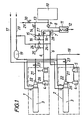
- two extraction sections 1 and 2 of identical construction are provided according to FIG. 1, each of which consists of an extraction probe 3 and two filters connected downstream of this extraction probe 3, namely a coarse filter 4 and a fine filter 5.
- These removal sections 1 and 2 are each connected with the aid of a gas line 6 via a switching device 7 to a feed line 8, which is provided with a feed pump 9 and conveys the gas sample to an analysis device 10.
- a cooler 11 with a condensate drain 12 is provided in the feed line 8 on the suction side of the feed pump 9.
- a connecting line 13 branches off from the feed line 8 with a pressure relief valve 14, which branches into two return lines 16 to the two gas lines 6, each of which can be shut off by a valve 15.
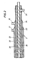
- a cooling liquid supply line 17 and a cooling liquid supply line 18 are provided for cooling the sampling probes 3.
- the sampling probes 3 can be used with compressed air against the direction of flow for sampling be blown through.
- a compressed air reservoir 19 is provided which can be acted upon by a compressed air source (not shown) via a compressed air line 20.
- This compressed air reservoir is connected to the gas-carrying inner tube 22 via blow lines 21, wherein the blow lines 21 can be released via valves 23.
- the arrangement is such that the blown air flows coaxially into the inner tube 22 of the sampling probes 3 and consequently has an advantageous cleaning effect.
- the compressed air line 20 is connected to the gas lines 6 via connecting lines 24, each with a shut-off valve 25. If one of the shut-off valves 25 is opened, the compressed air is first pressed through the fine filter 5 and then through the coarse filter 4 against the direction of flow of the gas withdrawn from the reaction chamber, before it passes through the outlet line 26 of the sampling probe 3 into the inner tube 22 and through the inner tube the reaction space flows.
- the gas sample is alternately removed from the reaction space via one of the two removal sections 1 and 2 and fed to the analysis device 10 via the switching device 7. If the gas sample is drawn off, for example, via the removal line 1, the gas line 6 of this removal line is connected to the feed line 8 via the switching device 7 by opening the valve 27 of the switching device 7 and closing the valve 28 in the gas line 6 of the removal line 2. The gas sample thus reaches the cooler 11, in which the condensate formed is removed, so that the now dry gas sample can be fed to the analysis device 10. Since a gas quantity exceeding the analysis requirement was withdrawn from the reaction space, the excess quantity is returned to the gas line 6 of the extraction line 2, specifically via the pressure relief valve 14 arranged in the connecting line 13 and one of the two return lines 16.
- the gas line 6 of the extraction line 2 leading return line 16 is opened for this purpose via the shut-off valve 15, while the return line 16 to the gas line 6 of the removal section 1 is shut off with the aid of the valve 15.
- the excess amount not required for the gas analysis is thus pressed against the direction of flow for the sampling first of all via the fine filter 5 and then via the coarse filter 4 into the probe 3 of the extraction section 2, from where it reaches the reaction space.
- This backwashing of the removal section 2 causes it to be cleaned of the deposited or retained solid particles, so that after a switchover of the switching device 7 and the valves 15 in the return lines 16, a gas sample can be drawn off through the cleaned removal section 2, while the removal section 1 of a cleaning rinse now is subjected to the excess gas quantity.
- the continuous sampling must not be interrupted for this blow-out, because the sampling can be continued through the other removal section.
- the shut-off valve 15 in the return line 16 to the gas line 6 of the removal line 1 is first closed and the blow-off line 29 connected to the feed line 8, which contains a pressure relief valve 30, is opened, so that the excess amount of gas can be blown off into the open .
- the valve 25 in the connecting line 24 between the compressed air line 20 and the gas line 6 of the removal section 1 is opened in order to be able to blow out the filters 5 and 4.
- the blow-off line 29 is closed after the valves 23 and 25 have been closed and the valve 15 has been opened in order to release the compressed air in the lines, the filters 4 and 5 and the removal probe 3 into the reaction space with the aid of the excess amount to be able to flush out sample gas, so that when switching over to sampling via removal section 1, the analysis result cannot be falsified by a compressed air component.
- the blowing out of the removal section 2 is carried out in an analogous manner.
- the sampling probes Since the gas sample has to be taken from a hot reaction chamber, the sampling probes have to be protected from an inadmissible temperature load by cooling.
- the inner tube 22 is surrounded by a two-part cooling jacket 31, through the outer annular gap 32 of which the cooling liquid, generally water, is supplied in order to be drawn off in counterflow after being deflected by an inner annular gap 33.
- the cooling liquid generally water
- Such cooling of the jacket 31 of the sampling probe 3 harbors the risk of falling below the dew point.
- the inner tube 22 is heated via an electrical resistance heater 34 to a temperature above the dew point of the gas sample, the inner tube 22 being shielded from the cooled jacket 31 by thermal insulation 35.
- This special Measure does not need to be considered for a special temperature profile in the jacket cooling, because even if the dew point temperature in the area of the coolant is not reached due to the heating of the inner tube 3, there is no fear of condensation in the inner tube 22.
Landscapes
- Health & Medical Sciences (AREA)
- Life Sciences & Earth Sciences (AREA)
- Engineering & Computer Science (AREA)
- Biomedical Technology (AREA)
- Molecular Biology (AREA)
- Physics & Mathematics (AREA)
- Chemical & Material Sciences (AREA)
- Analytical Chemistry (AREA)
- Biochemistry (AREA)
- General Health & Medical Sciences (AREA)
- General Physics & Mathematics (AREA)
- Immunology (AREA)
- Pathology (AREA)
- Sampling And Sample Adjustment (AREA)
Description
- Die Erfindung bezieht sich auf ein Verfahren zur kontinuierlichen Entnahme einer heißen Gasprobe aus einem Reaktionsraum für eine Gasanalyse, wobei die Gasprobe einer Analyseneinrichtung abwechselnd über zwei gleiche Entnahmestrecken mit je einer Entnahmesonde und wenigstens einem Filter zugeführt wird, sowie auf eine Vorrichtung zur Durchführung des Verfahrens.
- Um einen Prozeß in Abhängigkeit von der Zusammensetzung der beim Prozeßablauf entstehenden Gase zu steuern, werden dem Reaktionsraum Gasproben entnommen und einer Analyseneinrichtung zugeführt. Schwierige Verhältnisse sind dabei mit heissen staubbeladenen Gasen zu erwarten, wie sie beispielsweise bei der Kalzinierung von Rohmehl für die Zementherstellung anfallen. Die für die Entnahme der Gasproben aus dem Reaktionsraum vorgesehenen Entnahmesonden müssen nämlich aufgrund der hohen Gastemperaturen im Reaktionsraum gekühlt werden, was die Gefahr einer Taupunktunterschreitung im Bereich der Entnahmestrecke mit sich bringt, so daß sich durch das Kondensat und die mitgeführten Staubteilchen ein Schlamm bilden kann, der sich in der Entnahmesonde und im Bereich des an die Entnahmesonde angeschlossenen Filters absetzt und die Strömungswege für die Gasprobe verlegt. Es werden folglich periodische Reinigungsarbeiten erforderlich, um die Entnahmestrecke von den Ablagerungen zu befreien und das der Analyseneinrichtung vorgeschaltete Filter zu reinigen. Nachteilig bei diesen Reinigungsarbeiten ist nicht nur der hiefür erforderliche Aufwand, sondern vor allem der Umstand, daß während der Reinigungsarbeiten keine Gasprobe dem Reaktionsraum entnommen werden kann und daher die Prozeßsteuerung für diese Zeit ausgesetzt werden muß. Außerdem ist wegen der für die Gasanalyse erforderlichen, vergleichsweise geringen Gasmenge die Zeit, die die Gasprobe auf ihrem Strömungsweg vom Reaktionsraum bis zur Analyseneinrichtung benötigt, bei den gegebenen Strömungswegen lang, so daß die Prozeßsteuerung erst mit einer entsprechenden Zeitverzögerung Änderungen in der Gaszusammensetzung berücksichtigen kann.
- Um bei mehreren Reaktionsräumen mit einer Gasanalyseneinrichtung auszukommen, ist es bekannt (US-A-4 272 481), die an je einen Reaktionsraum angeschlossenen Entnahmesonden nacheinander mit der Gasanalyseneinrichtung zu verbinden, was die Möglichkeit eröffnet, die nicht mit der Analyseneinrichtung verbundenen Entnahmesonden zur Reinigung gegensinnig zur Entnahmerichtung mit Dampf zu durchblasen. Wegen des Vorsehens einer gemeinsamen Gasanalyseneinrichtung für alle Reaktionsräume ist eine kontinuierliche Probenentnahme aus den Reaktionsräumen von vorherein ausgeschlossen.
- Damit eine kontinuierliche Probenentnahme aus einem Reaktionsraum sichergestellt werden kann, ist es schließlich bekannt (US-A-3 748 906), zwei parallele Entnahmesonden vorzusehen, wobei während der Probenentnahme durch die eine Sonde die andere Sonde im Gegenstrom durch ein gesondertes Gas gereinigt wird. Nachteilig bei dieser bekannten Probenentnahme ist jedoch, daß ein gesondertes Reinigungsgas zur Verfügung stehen muß und dieses Gas in den Reaktionsraum eingeblasen wird. Außerdem wird bei einer Probenentnahme durch die gerade gereinigte Entnahmesonde das Analysenergebnis durch das noch im Bereich der Entnahmesonde befindliche Reinigungsgas verfälscht.
- Der Erfindung liegt somit die Aufgabe zugrunde, diese Mängel zu vermeiden und ein Verfahren zur kontinuierlichen Entnahme einer heißen Gasprobe aus einem Reaktionsraum anzugeben, bei dem kein gesondertes Reinigungsgas erforderlich ist, eine Verfälschung des Analysenergebnisses ausgeschlossen und die Ansprechzeit der Prozeßsteuerung erheblich verkürzt wird.
- Die Erfindung löst die gestellte Aufgabe dadurch, daß die Gasprobe den Reaktionsraum jeweils in einer den Analysenbedarf übersteigenden Menge über eine der beiden Entnahmestrecken entnommen wird und daß die Überschußmenge an entnommenem Gas vor der Analyse von der Gasprobe abgezweigt und über die jeweils andere Entnahmestrecke wieder in den Reaktionsraum zurückgeblasen wird.
- Durch das Zurückführen einer Überschußmenge an entnommenem Gas durch die jeweils nicht der Probenentnahme dienende Entnahmestrecke wird diese Entnahmestrecke entgegen der Strömungsrichtung für die Probenentnahme durchgeblasen und gereinigt, wobei im Filter zurückgehaltene Staubabscheidungen aus dem Filter gelöst und durch die Entnahmesonde wieder in den Reaktionsraum zurückgeführt werden. Diese Reinigung schließt ein fallweises Durchblasen der Entnahmestrecken mit Druckluft nicht aus. In diesem Falle wird die entnommene Überschußmenge an Probengas nicht in den Reaktionsraum zurückgeführt, sondern abgeblasen. Nach einer gesonderten Reinigung einer der Entnahmestrecken mit Druckluft kann diese Entnahmestrecke zunächst mit der Überschußmenge an Gas aus der anderen Entnahmestrecke gespült werden, um zu verhindern, daß das Analysenergebnis durch die sich sonst im Bereich der ausgeblasenen Entnahmestrecke befindliche Druckluft verfälscht wirc2.
- Die Entnahme einer den Analysenbedarf übersteigenden Gasmenge bringt darüber hinaus den Vorteil mit sich, daß der Durchmesser der Entnahmesonden vergrößert und damit die Gasströmung innerhalb der Entnahmesonden beruhigt werden kann, so daß sich bereits im Bereich der Gassonden ein erheblicher Staubanteil der Gasproben absetzen kann, was zu einer wesentlich geringeren Belastung der den Entnahmesonden nachgeschalteten Filter führt.
- Schließlich kann aufgrund der größeren Gasmenge der entnommenen Gasprobe die Strömungszeit zwischen dem Reaktionsraum und der Analyseneinrichtung wesentlich verkürzt werden, was sich unmittelbar in einem schnelleren Ansprechen der Prozeßsteuerung auf sich ändernde Prozeßverhältnisse auswirkt.
- Wird die Überschußmenge in weiterer Ausbildung der Erfindung nach einem Abkühlen der entnommenen Gesamtmenge und einem Ab führen des entstehenden Kondensates von der Gasprobe abgezweigt und zurückgeführt, so steht für die Rückspülung der jeweiligen Entnahmestrecke ein trockenes Gas zur Verfügung, das allenfalls im Bereich der Entnahmestrecke während der vorangegangenen Probenentnahme angesammelte Feuchtigkeit absorbiert. Damit wird die Reinigung der Entnahmestrecken zusätzlich unterstützt und die Gefahr eines Anbackens von Staubteilchen verringert.
- Zur Durchführung des Verfahrens kann von einer Vorrichtung mit einer Gasanalyseneinrichtung, die über zwei je eine Entnahmesonde und wenigstens ein Filter aufweisende Entnahmestrecken an einen Reaktionsraum anschließbar ist, und mit einer Umschalteinrichtung zum abwechseln den Verbinden der beiden Entnahmestrecken mit einer eine Förderpumpe aufweisenden Speiseleitung für die Analyseneinrichtung ausgegangen werden. Gegenüber herkömmlichen Vorrichtungen dieser Art unterscheidet sich die erfindungsgemäße jedoch dadurch, daß von der Speiseleitung der Analyseneinrichtung auf der Druckseite der Förderpumpe je eine absperrbare Rückleitung über wenigstens ein Überdruckventil zu den Entnahmestrecken abzweigt.
- Durch die Umschalteinrichtung können die Entnahmestrecken abwechselnd mit der Analyseneinrichtung verbunden werden, wobei die Gasförderung durch die zwischen der Umschalteinrichtung und der Analyseneinrichtung in der Speiseleitung vorgesehene Förderpumpe sichergestellt wird, und zwar in einer Menge, die den Analysenbedarf übersteigt. Die Oberschußmenge wird über ein Überdruckventil und die an die Speiseleitung angeschlossene Rückleitung in die nicht mit der Analyseneinrichtung verbundene Entnahmestrecke zurückgedrückt, die demzufolge einer Reinigungsspülung durch die Überschußmenge der entnommenen Gasprobe unterworfen wird.
- Soll eine der beiden Entnahmestrecken über die Reinigungsspülung durch die Überschußmenge an Probengas hinaus ausgeblasen werden, so darf die Überschußmenge nicht in die zu reinigende Entnahmestrecke zurückgeleitet werden. Zu diesem Zweck kann an die Speiseleitung eine absperrbare Abblasleitung über ein Überdruckventil angeschlossen sein, die unter gleichzeitigem Absperren der zugehörigen Rückleitung geöffnet wird, wenn die zugeordnete Entnahmestrecke mit Druckluft ausgeblasen werden soll.
- Da bei heißen Gasproben die Entnahmesonde vor einer unzulässigen Temperaturbelastung durch eine entsprechende Kühlung geschützt werden muß, besteht die Gefahr, daß der Taupunkt der Gasprobe unterschritten wird. Aufgrund der gegenüber bekannten Verfahren größeren Menge an entnommenem Probengas ist diese Gefahr zwar verringert, doch kann sie nur dann mit Sicherheit ausgeschaltet werden, wenn trotz der Kühlung der Entnahmesonden die beiden Entnahmestrecken mittels einer Heizung auf eine Temperatur über dem Taupunkt der Gasprobe erwärmt werden.
- Die Abkühlung der abwechselnd durch eine der beiden Entnahmestrecken dem Reaktionsraum entnommenen Gasprobe erfolgt dann in vorteilhafter Weise in einem Kühler in der Speiseleitung auf der Saugseite der Förderpumpe, so daß nur ein Kühler mit einer Kondensatabführung für beide Entnahmestrecken vorgesehen werden muß.
- An Hand der Zeichnung wird das erfindungsgemäße Verfahren näher erläutert. Es zeigen
- Fig. 1 eine erfindungsgemäße Vorrichtung zur kontinuierlichen Entnahme einer heißen Gasprobe aus einem Reaktionsraum in einem schematischen Blockschaltbild und
- Fig. 2 eine der beiden Entnahmesonden dieser Vorrichtung in einem Axialschnitt in einem größeren Maßstab.
- Zum Abziehen einer Gasprobe aus einem nicht dargestellten Reaktionsraum sind gemäß Fig. 1 zwei gleich aufgebaute Entnahmestrecken 1 und 2 vorgesehen, die jeweils aus einer Entnahmesonde 3 und zwei dieser Entnahmesonde 3 nachgeschalteten Filtern, nämlich einem Grobfilter 4 und einem Feinfilter 5, bestehen. Diese Entnahmestrecken 1 und 2 sind mit Hilfe je einer Gasleitung 6 über eine Umschalteinrichtung 7 an eine Speiseleitung 8 angeschlossen, die mit einer Förderpumpe 9 versehen ist und die Gasprobe einer Analyseneinrichtung 10 zufördert. Auf der Saugseite der Förderpumpe 9 ist in der Speiseleitung 8 ein Kühler 11 mit einer Kondensatabführung 12 vorgesehen. Auf der Druckseite der Förderpumpe 9 zweigt von der Speiseleitung 8 eine Anschlußleitung 13 mit einem Überdruckventil 14 ab, die sich in zwei durch je ein Ventil 15 absperrbare Rückleitungen 16 zu den beiden Gasleitungen 6 verzweigt.
- Zur Kühlung der Entnahmesonden 3 ist eine Kühlflüssigkeitszuleitung 17 und eine Kühlflüssigkeitsableitung 18 vorgesehen. Außerdem können die Entnahmesonden 3 mit Hilfe von Druckluft entgegen der Strömungsrichtung für die Probenentnahme durchblasen werden. Zu diesem Zweck ist ein Druckluftspeicher 19 vorgesehen, der über eine Druckluftleitung 20 von einer nicht dargestellten Druckluftquelle beaufschlagt werden kann. Dieser Druckluftspeicher ist über Blasleitungen 21 mit dem gasführenden Innenrohr 22 verbunden, wobei die Blasleitungen 21 über Ventile 23 freigegeben werden können. Wie der Fig. 2 entnommen werden kann, ist die Anordnung dabei so getroffen, daß die Blasluft koaxial in das Innenrohr 22 der Entnahmesonden 3 strömt und folglich eine vorteilhafte Reinigungswirkung mit sich bringt. Zum Ausblasen der Filter 4 und 5 ist die Druckluftleitung 20 über Verbindungsleitungen 24 mit je einem Absperrventil 25 an die Gasleitungen 6 angeschlossen. Wird eines der Absperrventile 25 geöffnet, so wird die Druckluft entgegen der Strömungsrichtung des dem Reaktionsraum entnommenen Gases zunächst durch das Feinfilter 5 und dann durch das Grobfilter 4 gedrückt, bevor sie durch die Austrittsleitung 26 der Entnahmesonde 3 in das Innenrohr 22 und durch das Innenrohr in den Reaktionsraum strömt.
- Die Gasprobe wird abwechselnd über eine der beiden Entnahmestrecken 1 und 2 dem Reaktionsraum entnommen und über die Umschalteinrichtung 7 der Analyseneinrichtung 10 zugeführt. Wird die Gasprobe beispielsweise über die Entnahmestrecke 1 abgezogen, so wird die Gasleitung 6 dieser Entnahmestrecke über die Umschalteinrichtung 7 an die Speiseleitung 8 angeschlossen, indem das Ventil 27 der Umschalteinrichtung 7 geöffnet und das Ventil 28 in der Gasleitung 6 der Entnahmestrecke 2 geschlossen wird. Die Gasprobe gelangt somit zum Kühler 11, in dem das entstehende Kondensat abgeführt wird, so daß die nunmehr trockene Gasprobe der Analyseneinrichtung 10 zugeführt werden kann. Da dem Reaktionsraum eine den Analysenbedarf übersteigende Gasmenge entnommen wurde, wird die Überschußmenge in die Gasleitung 6 der Entnahmestrecke 2 zurückgeführt, und zwar über das in der Anschlußleitung 13 angeordnete Überdruckventil 14 und die eine der beiden Rückleitungen 16. Die in die Gasleitung 6 der Entnahmestrecke 2 führende Rückleitung 16 ist zu diesem Zweck über das Absperrventil 15 geöffnet, während die Rückleitung 16 zur Gasleitung 6 der Entnahmestrecke 1 mit Hilfe des Ventiles 15 abgesperrt wird. Die für die Gasanalyse nicht benötigte Überschußmenge wird somit entgegen der Strömungsrichtung für die Probenentnahme zunächst über das Feinfilter 5 und dann über das Grobfilter 4 in die Sonde 3 der Entnahmestrecke 2 gedrückt, von wo sie in den Reaktionsraum gelangt. Diese Rückspülung der Entnahmestrecke 2 bewirkt deren Reinigung von den abgesetzten bzw. zurückgehaltenen Feststoffteilchen, so daß nach einem Umschalten der Umschalteinrichtung 7 und der Ventile 15 in den Rückleitungen 16 eine Gasprobe durch die gereinigte Entnahmestrecke 2 abgezogen werden kann, während nunmehr die Entnahmestrecke 1 einer Reinigungsspülung mit der Gasüberschußmenge unterworfen wird.
- Soll trotz dieser Reinigungsspülungen eine der beiden Entnahmestrecken mit Hilfe von Druckluft ausgeblasen werden, so braucht für dieses Aus blasen die kontinuierliche Probenentnahme nicht unterbrochen zu werden, weil ja die Probenentnahme durch die jeweils andere Entnahmestrecke weitergeführt werden kann. Zum Ausblasen beispielsweise der Entnahmestrecke 1 wird zunächst das Absperrventil 15 in der Rückleitung 16 zur Gasleitung 6 der Entnahmestrecke 1 geschlossen und die an die Speiseleitung 8 angeschlossene Abblasleitung 29, die ein Überdruckventil 30 enthält, geöffnet, so daß die überschüssige Gasmenge ins Freie abgeblasen werden kann. Danach wird das Ventil 25 in der Verbindungsleitung 24 zwischen der Druckluftleitung 20 und der Gasleitung 6 der Entnahmestrecke 1 geöffnet, um die Filter 5 und 4 ausblasen zu können. Erst nach einer entsprechenden Durchblaszeit wird das Ventil 23 in der Blasleitung 21 der Entnahmestrecke 1 geöffnet und das Innenrohr 22 der Entnahmesonde 3 durchgeblasen, damit nicht durch die Druckluft aus der Leitung 21 das Ablösen der ausgefilterten Staubteilchen aus den Filtern 4 und 5 beeinträchtigt werden kann. Der Druck der Blasluft aus der Blasleitung 21 wirkt ja dem Blasluftstrom aus der Gasleitung 6 entgegen. Nach der Reinigung der Entnahmestrecke 1 wird die Abblasleitung 29 nach einem Schließen der Ventile 23 und 25 und einem Öffnen des Ventiles 15 geschlossen, um die in den Leitungen, den Filtern 4 und 5 und der Entnahmesonde 3 befindliche Druckluft in den Reaktionsraum mit Hilfe der Überschußmenge an Probengas ausspülen zu können, so daß bei einer Umschaltung auf eine Probenentnahme über die Entnahmestrecke 1 das Analysenergebnis nicht durch einen Druckluftanteil verfälscht werden kann. Zum Ausblasen der Entnahmestrecke 2 wird in analoger Weise vorgegangen.
- Da die Gasprobe einem heißen Reaktionsraum entnommen werden muß, müssen die Entnahmesonden durch eine Kühlung vor einer unzulässigen Temperaturbelastung geschützt werden. Zu diesem Zweck ist das Innenrohr 22 mit einem zweiteiligen Kühlmantel 31 umgeben, durch dessen äußeren Ringspalt 32 die Kühlflüssigkeit, im allgemeinen Wasser, zugeführt wird, um nach einer Umlenkung durch einen inneren Ringspalt 33 im Gegenstrom abgezogen zu werden. Eine solche Kühlung des Mantels 31 der Entnahmesonde 3 birgt allerdings die Gefahr einer Taupunktunterschreitung in sich. Zur Vermeidung einer Taupunktunterschreitung wird das Innenrohr 22 über eine elektrische Widerstandsheizung 34 auf eine über dem Taupunkt der Gasprobe liegende Temperatur erwärmt, wobei das Innenrohr 22 gegenüber dem gekühlten Mantel 31 durch eine Wärmeisolierung 35 abgeschirmt ist. Durch diese besondere Maßnahme braucht nicht auf einen besonderen Temperaturverlauf bei der Mantelkühlung geachtet zu werden, weil auch bei einer Unterschreitung der Taupunkttemperatur im Bereich der Kühlflüssigkeit aufgrund der Heizung des Innenrohres 3 keine Kondensierung im Innenrohr 22 zu befürchten ist.
Claims (6)
Priority Applications (6)
| Application Number | Priority Date | Filing Date | Title |
|---|---|---|---|
| EP86890119A EP0243569B1 (de) | 1986-04-29 | 1986-04-29 | Verfahren und Vorrichtung zur kontinuierlichen Entnahme einer heissen Gasprobe aus einem Reaktionsraum für eine Gasanalyse |
| DE8686890119T DE3660941D1 (en) | 1986-04-29 | 1986-04-29 | Method and apparatus for continuous hot gas sampling for analysis in a reactor |
| AT86890119T ATE37955T1 (de) | 1986-04-29 | 1986-04-29 | Verfahren und vorrichtung zur kontinuierlichen entnahme einer heissen gasprobe aus einem reaktionsraum fuer eine gasanalyse. |
| US07/030,151 US4779466A (en) | 1986-04-29 | 1987-03-25 | Method and apparatus for continuously taking a hot gas sample to be analyzed from a reaction chamber |
| CA000533984A CA1290169C (en) | 1986-04-29 | 1987-04-07 | Probe for extracting hot sample gas |
| DD30215587A DD256373A5 (de) | 1986-04-29 | 1987-04-27 | Verfahren und Vorrichtung zur kontinuierlichen Entnahme einer heißen Gasprobe aus einem Reaktionsraum für eine Gasanalyse |
Applications Claiming Priority (1)
| Application Number | Priority Date | Filing Date | Title |
|---|---|---|---|
| EP86890119A EP0243569B1 (de) | 1986-04-29 | 1986-04-29 | Verfahren und Vorrichtung zur kontinuierlichen Entnahme einer heissen Gasprobe aus einem Reaktionsraum für eine Gasanalyse |
Publications (2)
| Publication Number | Publication Date |
|---|---|
| EP0243569A1 EP0243569A1 (de) | 1987-11-04 |
| EP0243569B1 true EP0243569B1 (de) | 1988-10-12 |
Family
ID=8196564
Family Applications (1)
| Application Number | Title | Priority Date | Filing Date |
|---|---|---|---|
| EP86890119A Expired EP0243569B1 (de) | 1986-04-29 | 1986-04-29 | Verfahren und Vorrichtung zur kontinuierlichen Entnahme einer heissen Gasprobe aus einem Reaktionsraum für eine Gasanalyse |
Country Status (6)
| Country | Link |
|---|---|
| US (1) | US4779466A (de) |
| EP (1) | EP0243569B1 (de) |
| AT (1) | ATE37955T1 (de) |
| CA (1) | CA1290169C (de) |
| DD (1) | DD256373A5 (de) |
| DE (1) | DE3660941D1 (de) |
Cited By (1)
| Publication number | Priority date | Publication date | Assignee | Title |
|---|---|---|---|---|
| DE102006019723A1 (de) * | 2006-03-31 | 2007-10-04 | Alstom Technology Ltd. | Messsondensystem, Anordnung und Verfahren zur Erfassung von Abgasparametern stromabwärts einer Gasturbine |
Families Citing this family (30)
| Publication number | Priority date | Publication date | Assignee | Title |
|---|---|---|---|---|
| CA1311627C (en) * | 1988-01-11 | 1992-12-22 | Kurt Holzl | Apparatus for extracting hot gas samples from a reaction vessel |
| ATE76193T1 (de) * | 1988-01-11 | 1992-05-15 | Voest Alpine Ind Anlagen | Vorrichtung zur kontinuierlichen entnahme heisser gasproben aus einem reaktionsgefaess. |
| GB2234063B (en) * | 1989-07-04 | 1993-01-20 | British Gas Plc | Gas sampling device |
| US5235190A (en) * | 1991-01-29 | 1993-08-10 | Gemini Research, Inc. | Continuous air monitoring system |
| DE9101433U1 (de) * | 1991-02-08 | 1991-04-25 | Steag Ag, 4300 Essen | Gehäuse zur Aufnahme eines Staubfilters für eine Gasentnahmesonde |
| FR2715732B1 (fr) * | 1994-02-02 | 1996-03-15 | Inst Francais Du Petrole | Dispositif de prélèvement fonctionnant dans des milieux à forte concentration en poussières. |
| US5507192A (en) * | 1994-09-13 | 1996-04-16 | Beaudin; Allen B. | Automated gas measurement system |
| US5777241A (en) * | 1997-02-06 | 1998-07-07 | Evenson; Euan J. | Method and apparatus for sampling and analysis of furnace off-gases |
| FR2764696B1 (fr) * | 1997-06-17 | 1999-08-13 | Inst Francais Du Petrole | Dispositif de prelevement d'echantillons de fluide comportant une vanne de controle a commande thermique |
| DE19733837C2 (de) | 1997-08-06 | 2000-07-27 | Aventis Res & Tech Gmbh & Co | Verfahren zur quantitativen On-Line-Analyse einer reaktiven Gasmischung |
| GB9810866D0 (en) * | 1998-05-20 | 1998-07-22 | Boc Group Plc | Furnace waste gas sampling |
| FR2780506B1 (fr) * | 1998-06-25 | 2000-08-25 | Inst Francais Du Petrole | Procede et unite de prelevement d'aldehydes et cetones contenus dans des gaz d'echappement |
| JP2000081422A (ja) * | 1998-06-29 | 2000-03-21 | Nec Corp | 多点極微量物質自動分析装置及び分析方法並びに極微量物質自動分析装置及び分析方法 |
| JP2000028579A (ja) * | 1998-07-08 | 2000-01-28 | Hitachi Ltd | 試料ガス採取装置及び危険物探知装置 |
| FI110033B (fi) * | 1998-07-09 | 2002-11-15 | Outokumpu Oy | Näytevirran ohjauselin |
| US6151952A (en) * | 1998-10-26 | 2000-11-28 | California Analytical Instruments, Inc. | System for mass emission sampling of combustion products |
| FR2795338B1 (fr) * | 1999-06-28 | 2001-08-03 | Inst Francais Du Petrole | Dispositif de distribution pour multi-reacteurs d'evaluation automatique de catalyseurs |
| US6499362B1 (en) * | 2001-12-03 | 2002-12-31 | Global Fia, Inc. | In-line filter probe for process analysis |
| FI116161B (fi) * | 2002-12-23 | 2005-09-30 | Outokumpu Oy | Menetelmä ja laitteisto kaasun koostumuksen mittaamiseksi leijupedistä |
| DE10315996A1 (de) * | 2003-04-07 | 2004-10-28 | Sobotta Gmbh, Sondermaschinenbau | Sonde zur Entnahme einer Gasprobe |
| US7395725B2 (en) * | 2005-12-19 | 2008-07-08 | Horiba, Ltd. | Sample treatment apparatus and sample measurement apparatus providing it |
| ITMI20060523A1 (it) * | 2006-03-22 | 2007-09-23 | Tct Tecora S R L | Sistema per il campionamento continuo delle emissioni |
| CN101936820B (zh) * | 2009-06-30 | 2012-03-07 | 同方威视技术股份有限公司 | 样品收集方法以及样品收集装置 |
| US8196479B2 (en) * | 2009-10-20 | 2012-06-12 | Midwest Research Institute, Inc. | Portable multi-tube air sampler unit |
| FR2959311A1 (fr) * | 2010-04-22 | 2011-10-28 | Commissariat Energie Atomique | Sonde de prelevement d'echantillons, dispositif de prelevement comportant cette sonde et procede de prelevement d'echantillons |
| AT12381U3 (de) * | 2011-12-06 | 2012-09-15 | Avl List Gmbh | Vorfilteranordnung für gasanalysesysteme |
| CN110579378B (zh) * | 2018-06-07 | 2024-06-21 | 北京航天益来电子科技有限公司 | 烟气可持续采样探杆 |
| US11287406B2 (en) * | 2019-04-15 | 2022-03-29 | Mustang Sampling, Llc | Multi-input auto-switching gas sample conditioning system |
| DK180857B1 (en) * | 2020-01-13 | 2022-05-20 | Flo2R Aps | Gas sampling apparatus for extraction of gaseous samples |
| CN112362417B (zh) * | 2020-11-21 | 2025-02-14 | 西安热工研究院有限公司 | 一种双脉冲差相反吹烟气采样装置及方法 |
Family Cites Families (5)
| Publication number | Priority date | Publication date | Assignee | Title |
|---|---|---|---|---|
| US3748906A (en) * | 1970-10-15 | 1973-07-31 | Jones & Laughlin Steel Corp | Gas sampling apparatus |
| JPS5814976B2 (ja) * | 1976-08-19 | 1983-03-23 | トヨタ自動車株式会社 | エンジンの図示平均有効圧力変動率測定方法及び装置 |
| US4272481A (en) * | 1979-05-21 | 1981-06-09 | The Dow Chemical Company | System and method for providing a vapor phase sample for analysis |
| EP0081637A1 (de) * | 1981-11-10 | 1983-06-22 | Krupp Polysius Ag | Entnahme- und Analysiervorrichtung für staubhaltige Gasproben |
| BE893366A (fr) * | 1982-05-28 | 1982-09-16 | Centre Rech Metallurgique | Perfectionnements aux dispositifs de prelevement d'echantillons gazeux |
-
1986
- 1986-04-29 DE DE8686890119T patent/DE3660941D1/de not_active Expired
- 1986-04-29 EP EP86890119A patent/EP0243569B1/de not_active Expired
- 1986-04-29 AT AT86890119T patent/ATE37955T1/de not_active IP Right Cessation
-
1987
- 1987-03-25 US US07/030,151 patent/US4779466A/en not_active Expired - Lifetime
- 1987-04-07 CA CA000533984A patent/CA1290169C/en not_active Expired - Lifetime
- 1987-04-27 DD DD30215587A patent/DD256373A5/de unknown
Cited By (1)
| Publication number | Priority date | Publication date | Assignee | Title |
|---|---|---|---|---|
| DE102006019723A1 (de) * | 2006-03-31 | 2007-10-04 | Alstom Technology Ltd. | Messsondensystem, Anordnung und Verfahren zur Erfassung von Abgasparametern stromabwärts einer Gasturbine |
Also Published As
| Publication number | Publication date |
|---|---|
| DE3660941D1 (en) | 1988-11-17 |
| ATE37955T1 (de) | 1988-10-15 |
| US4779466A (en) | 1988-10-25 |
| CA1290169C (en) | 1991-10-08 |
| DD256373A5 (de) | 1988-05-04 |
| EP0243569A1 (de) | 1987-11-04 |
Similar Documents
| Publication | Publication Date | Title |
|---|---|---|
| EP0243569B1 (de) | Verfahren und Vorrichtung zur kontinuierlichen Entnahme einer heissen Gasprobe aus einem Reaktionsraum für eine Gasanalyse | |
| DE1811815A1 (de) | Vorrichtung zur diskontinuierlichen Probenahme aus einem Gasgemisch | |
| DE69300334T2 (de) | Kontaminationsmotor für überkristische Flüssigkeiten. | |
| EP0343471A1 (de) | Verfahren zum Aufarbeiten von Abfallmaterial | |
| DE69412136T2 (de) | Verfahren und vorrichtung zur schnellen kontinuierlichen analyse eines gasgemisches | |
| EP0755712A1 (de) | Verfahren und Vorrichtung zum Reinigen von staubbeladenem Gas | |
| DE3324803A1 (de) | Staubabscheidegeraet | |
| WO2004053023A1 (de) | Koksofengaskühler | |
| DE3422093A1 (de) | Entstaubungseinrichtung | |
| DD148172A3 (de) | Verfahren und anordnung zur kontinuierlichen probenahme von rohgasen | |
| DE3622145A1 (de) | Vorrichtung zum entfernen von kondensierbaren bestandteilen aus gasen | |
| DE3505729A1 (de) | Verfahren zur reinigung von filterelementen | |
| WO1987007179A1 (fr) | Procede et dispositif de surveillance de l'ecoulement d'un courant de gaz sortant d'un filtre | |
| EP0324331B1 (de) | Vorrichtung zur kontinuierlichen Entnahme heisser Gasproben aus einem Reaktionsgefäss | |
| DE19527557B4 (de) | Verfahren und Vorrichtung zur Reinigung von Gasen | |
| DE102021124693A1 (de) | Messgassonde, Messsystem und Verfahren zur Messung von gasförmigen Rauchgasbestandteilen | |
| WO1992014130A1 (de) | Einrichtung in aggregaten zur messgasaufbereitung für die gasanalyse | |
| DE3736521C1 (de) | Verfahren und Vorrichtung zum Kuehlen von Flugstaub | |
| EP0451345A2 (de) | Vorrichtung zur Vorbereitung von Gasproben für die Analyse | |
| DE3344163C2 (de) | ||
| DE870243C (de) | Verfahren und Vorrichtung zur Abtrennung von Fluessigkeiten aus Gasgemischen | |
| DE202021105125U1 (de) | Messgassonde und Messsystem zur Messung von gasförmigen Rauchgasbestandteilen | |
| DE2836772C2 (de) | Vorrichtung zum Entfernen von Feststoffen aus einem in einem Wirbelbett behandelten Gas | |
| DE4111377C2 (de) | ||
| DE19535214C2 (de) | Gasentnahmesonde |
Legal Events
| Date | Code | Title | Description |
|---|---|---|---|
| PUAI | Public reference made under article 153(3) epc to a published international application that has entered the european phase |
Free format text: ORIGINAL CODE: 0009012 |
|
| AK | Designated contracting states |
Kind code of ref document: A1 Designated state(s): AT BE CH DE FR GB IT LI LU NL SE |
|
| 17P | Request for examination filed |
Effective date: 19871001 |
|
| 17Q | First examination report despatched |
Effective date: 19880201 |
|
| RAP1 | Party data changed (applicant data changed or rights of an application transferred) |
Owner name: VOEST-ALPINE INDUSTRIEANLAGENBAU GESELLSCHAFT M.B. |
|
| GRAA | (expected) grant |
Free format text: ORIGINAL CODE: 0009210 |
|
| AK | Designated contracting states |
Kind code of ref document: B1 Designated state(s): AT BE CH DE FR GB IT LI LU NL SE |
|
| REF | Corresponds to: |
Ref document number: 37955 Country of ref document: AT Date of ref document: 19881015 Kind code of ref document: T |
|
| REF | Corresponds to: |
Ref document number: 3660941 Country of ref document: DE Date of ref document: 19881117 |
|
| GBT | Gb: translation of ep patent filed (gb section 77(6)(a)/1977) | ||
| ITF | It: translation for a ep patent filed | ||
| ET | Fr: translation filed | ||
| PLBE | No opposition filed within time limit |
Free format text: ORIGINAL CODE: 0009261 |
|
| STAA | Information on the status of an ep patent application or granted ep patent |
Free format text: STATUS: NO OPPOSITION FILED WITHIN TIME LIMIT |
|
| 26N | No opposition filed | ||
| ITTA | It: last paid annual fee | ||
| EPTA | Lu: last paid annual fee | ||
| EAL | Se: european patent in force in sweden |
Ref document number: 86890119.0 |
|
| REG | Reference to a national code |
Ref country code: GB Ref legal event code: IF02 |
|
| PGFP | Annual fee paid to national office [announced via postgrant information from national office to epo] |
Ref country code: SE Payment date: 20050412 Year of fee payment: 20 Ref country code: NL Payment date: 20050412 Year of fee payment: 20 Ref country code: FR Payment date: 20050412 Year of fee payment: 20 Ref country code: CH Payment date: 20050412 Year of fee payment: 20 |
|
| PGFP | Annual fee paid to national office [announced via postgrant information from national office to epo] |
Ref country code: AT Payment date: 20050414 Year of fee payment: 20 |
|
| PGFP | Annual fee paid to national office [announced via postgrant information from national office to epo] |
Ref country code: LU Payment date: 20050415 Year of fee payment: 20 |
|
| PGFP | Annual fee paid to national office [announced via postgrant information from national office to epo] |
Ref country code: GB Payment date: 20050418 Year of fee payment: 20 Ref country code: DE Payment date: 20050418 Year of fee payment: 20 |
|
| PGFP | Annual fee paid to national office [announced via postgrant information from national office to epo] |
Ref country code: IT Payment date: 20050421 Year of fee payment: 20 |
|
| PGFP | Annual fee paid to national office [announced via postgrant information from national office to epo] |
Ref country code: BE Payment date: 20050509 Year of fee payment: 20 |
|
| PG25 | Lapsed in a contracting state [announced via postgrant information from national office to epo] |
Ref country code: GB Free format text: LAPSE BECAUSE OF EXPIRATION OF PROTECTION Effective date: 20060428 |
|
| PG25 | Lapsed in a contracting state [announced via postgrant information from national office to epo] |
Ref country code: NL Free format text: LAPSE BECAUSE OF EXPIRATION OF PROTECTION Effective date: 20060429 |
|
| REG | Reference to a national code |
Ref country code: GB Ref legal event code: PE20 |
|
| REG | Reference to a national code |
Ref country code: CH Ref legal event code: PL |
|
| EUG | Se: european patent has lapsed | ||
| NLV7 | Nl: ceased due to reaching the maximum lifetime of a patent |
Effective date: 20060429 |
|
| BE20 | Be: patent expired |
Owner name: *VOEST-ALPINE INDUSTRIEANLAGENBAU G.M.B.H. Effective date: 20060429 |