EP0243246A2 - Vorrichtung zum Sammeln und Entfernen von Produkten, nämlich von Müll - Google Patents
Vorrichtung zum Sammeln und Entfernen von Produkten, nämlich von Müll Download PDFInfo
- Publication number
- EP0243246A2 EP0243246A2 EP87400866A EP87400866A EP0243246A2 EP 0243246 A2 EP0243246 A2 EP 0243246A2 EP 87400866 A EP87400866 A EP 87400866A EP 87400866 A EP87400866 A EP 87400866A EP 0243246 A2 EP0243246 A2 EP 0243246A2
- Authority
- EP
- European Patent Office
- Prior art keywords
- sleeve
- frustoconical
- base
- plane
- work
- Prior art date
- Legal status (The legal status is an assumption and is not a legal conclusion. Google has not performed a legal analysis and makes no representation as to the accuracy of the status listed.)
- Granted
Links
Images


Classifications
-
- B—PERFORMING OPERATIONS; TRANSPORTING
- B65—CONVEYING; PACKING; STORING; HANDLING THIN OR FILAMENTARY MATERIAL
- B65F—GATHERING OR REMOVAL OF DOMESTIC OR LIKE REFUSE
- B65F1/00—Refuse receptacles; Accessories therefor
- B65F1/14—Other constructional features; Accessories
- B65F1/1426—Housings, cabinets or enclosures for refuse receptacles
- B65F1/1431—Housings, cabinets or enclosures for refuse receptacles having a waste disposal chute integrally connected to a work top or the like, the refuse receptacle remaining static
-
- B—PERFORMING OPERATIONS; TRANSPORTING
- B65—CONVEYING; PACKING; STORING; HANDLING THIN OR FILAMENTARY MATERIAL
- B65F—GATHERING OR REMOVAL OF DOMESTIC OR LIKE REFUSE
- B65F1/00—Refuse receptacles; Accessories therefor
- B65F1/04—Refuse receptacles; Accessories therefor with removable inserts
- B65F1/06—Refuse receptacles; Accessories therefor with removable inserts with flexible inserts, e.g. bags or sacks
Definitions
- the present invention relates to a device for household or professional use intended to allow the collection in a container provided for this purpose of various elements or products such as waste or garbage to be disposed of.
- the present invention finds a particularly advantageous application in the field of collection, at the family level, of household waste with a view to their disposal in a single container and more especially consisting of a flexible bag of disposable synthetic material of known type.
- the invention is not limited to this preferred application and may find use on a professional level, particularly in the workshop, with a view to making it possible to bring together elements in a manufacturing process and consisting either of products originating from this manufacturing, or waste or debris intended for disposal.
- the invention allows in particular the installation of a collector formed by a funnel provided with a cover installed in a fixed position and therefore arranged under ergonomic conditions, at the place where the distance to be traveled for the hand in sight evacuation of the product or waste, will be minimum without however cluttering the work plan by the establishment of a container provided for the reception of the products or waste thus collected.
- Devices which allow products or debris or waste from a manufacturing process or housework to be collected in a container capable of being subsequently discharged.
- a removable element such as for example a movable trolley which can be brought near the work station;
- this removable cart is difficult to integrate into ergonomic conditions at the work station and it generally represents a foreign element constituting a hindrance for the movements of the operator, particularly in a kitchen where the user will have to move the cart which will necessarily be found. on its way when it is near the work plan; so that the operator must either leave the trolley away and in this case the evacuation of the products or debris will require a displacement or, in another solution, the operator will have to during each task move the trolley for the bring close to the worktop.
- French patent 81 17954 in the name of the applicant is a device which can be built into a worktop to receive in a lower position a container and in particular a plastic bag making it possible to collect the products or waste discharged from the worktop.
- the present invention relates to an improved device of this type allowing better operating installation conditions, in particular as regards maintenance in hygienic and clean conditions as well as the installation facilities.
- the invention relates to a device for the collection of various items or products such as household waste and refuse, intended to be collected in a container such as a flexible plastic bag and disposable, for their disposal within said bag, the device being of the type comprising a sleeve capable of passing through a fixed horizontal plane such as a work surface, in particular of a kitchen, to open on one side at its upper part, above or at level of said plane, by an opening provided with a removable cover, said sleeve being able to overhang by its lower part a removable container receiving said products or waste, and the device is characterized in that the sleeve is constituted by a body of revolution formed of two truncated cones opposite by their small base and consequently comprising in the upper part a frustoconical part whose large base is located upwards and forming hopper and this frustoconical part is ra ccorded to a lower skirt formed of an inverted truncated cone and whose flare is oriented downwards
- the hopper cone disposed at the upper part allows debris or waste to be directed precisely towards the central part of the lower container, thus avoiding any contact of these possibly polluting or dirty elements with the lower part of the sleeve.
- the lower divergent down skirt provides a "leaky” surface towards the outside and thus prevents this lower part of the sleeve from receiving projections or contacts with dirtying elements so that this lower part, which is necessarily more difficult to access, can be kept clean being removed from the path of debris or waste; while the upper frusto-conical part, the diverging part of which faces upwards, can be easily stored and cleaned.
- inverted frustoconical skirt disposed in the lower position of the sleeve will allow to connect and secure under particularly effective conditions a receptacle such as a flexible bag.
- the outer periphery of the lower skirt is associated with a clamping collar for the establishment and maintenance of the walls of a removable flexible bag of the disposable type.
- the clamping collar consists of a belt of rigid elastically deformable material, such as steel, these two ends being joined by a clamping system of the "toggle" type.
- the frustoconical upper part, forming a hopper, of the sleeve cooperates with a removable cover whose periphery, coming into contact with the internal frustoconical surface of the sleeve comprises at least one lip whose bearing edge on the frustoconical internal surface of the sleeve is defined by a determining angle thus a linear and circular support of said lip on the frustoconical wall forming hopper of said sleeve.
- the removable cover has at its periphery two superimposed circular lips and of decreasing diameter from top to bottom, such that the angular edges of said lips come to bear at two levels superimposed on the frustoconical inner wall of said sleeve thereby causing a closure hermetic of the sleeve by two superimposed circular contacts.
- the sleeve has at its upper part a flange capable of projecting slightly above the support plane, such as the work surface traversed by the sleeve, said flange extending peripherally outwards beyond the opening made in said work plan.
- said collar has an edge which tapers towards the periphery to come to die at the level of the upper work plane traversed by said sleeve.
- the disc has on its upper face a circular hollow part and coaxial with said disc, this circular recess being capable of receiving a decorative surfacing element capable of being harmonized with the surfacing of said work surface.
- the circular connection zone between the two inverted cones has an inward rim forming a "drop of water” causing the liquid elements introduced into the funnel to fall into the interior of the bag and avoiding the flow of said liquid along the internal face of the lower skirt.
- the outer wall of the frusto-conical upper part of the sleeve, forming a funnel has a cylindrical periphery provided with grooves to facilitate the bonding by bonding to the interior bore of the opening made in the work plan.
- the circular base of the sleeve corresponding to the large base of the inverted frustoconical part of said sleeve has a diameter identical to said cylindrical bonding wall, that is to say at the opening required and to be practiced in the work plan, the layout of this opening being thus facilitated from the base of the sleeve placed on said work plan and the circumference of which can be easily transferred onto this plan.
- the sleeve comprises a flexible tubular structure of the disposable type, fitted on the outer wall of the base in the form of an inverted truncated cone of said sleeve, on which it is held integral by the collar of tightening, the lower part of said flexible tubular structure leading to a container located in the lower position possibly on a lower floor of the room.
- the sleeve is connected to a rigid tubular structure fitted on the base in the form of inverted truncated cone of said sleeve, with interposition of seals, the flexible tubular structure extending downwards until it leads to a container located in the lower position possibly on a floor located under the work room.
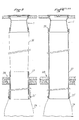
- the sleeve 1 passes through an opening 4 arranged in the work plane 5.
- the sleeve has two parts, namely an upper part 2 in the form of a truncated cone, connected to a lower part or skirt 3 in the form of an inverted truncated cone, the two truncated cones 2 and 3 being opposed by their small base .
- the surface 6 forming the internal wall of the upper conical part 2 thus constitutes a hopper, the diverging part of which is oriented upwards and therefore makes it possible to receive and collect consequently towards the lower central part all the elements, in particular waste or debris which are introduced into the frustoconical space defined by the upper part 2 of the sleeve from the zone located above the work surface.
- the frustoconical upper part 2 of the sleeve plays the role of hopper making it possible to collect by sliding by hand on the work surface the elements, in particular the waste to be removed, this frustoconical part forming hopper thus easily allowing the waste to be moved from the worktop to the interior space.
- the lower part 3 constitutes a skirt which diverges towards the periphery and this skirt is subtracted by its shape in contact with the flowing elements. from the hopper 6.
- a cover 9 is provided to close the opening of the frustoconical part 2 forming an introduction hopper.
- This cover 9 comprises, on the one hand, a central disc, the periphery of which ends at a right angle, so that the lower angle 11 comes into bearing contact along a linear circumference on the upper part of the frustoconical wall 6.
- the cover 9 comprises, in the lower part relative to the disc 10, a cylindrical crown 12 also terminating at its base at a right angle, the angle 13 being provided to ensure a second linear circumferential contact on the wall 6.
- the two contacts make it possible to ensure a perfect seal of the cover relative to the wall 6 forming an introduction hopper.
- This arrangement allows the positioning on the disc 10 of a surfacing element 16 capable of being harmonized and of coming substantially at the level of the surfacing 15 equipping the work surface 5.
- the central part of the cover comprises, in a known manner, a hollow boss 17 allowing the insertion of the bar 18 for gripping the cover.
- the upper frustoconical part 2 is equipped in its upper zone with an external cylindrical crown 19 provided with grooves 20,21.
- This cylindrical surface 19 as well as the grooves 20, 21 make it possible to facilitate blocking and securing, in particular by gluing, of this cylindrical part of the sleeve in the bore 4 provided in the work plan.
- this cylindrical part 19 ends at its upper part by a flange 22 projecting outwards and tapering to die at the level of the upper plane of the surfacing element 15; this makes it possible to facilitate the routing, by sliding, if necessary by hand, of the elements to be evacuated which can be "swept" from the upper surface of the worktop 5 to the upper orifice of the frustoconical part 2 forming a hopper, the elements thus sliding along the work surface and being able to easily overcome the slight obstacle constituted by the flange 22 which is connected by a slight slope on this work surface.
- the flange 22 projecting relative to the bore 4 makes it possible to hide the slight imperfections resulting from the work of the material when the bore 4 has been produced; a perfect aesthetic device is thus obtained while facilitating its operating conditions.
- the base 23 of the inverted frustoconical skirt 3 to form a circle with a diameter identical to the cylindrical part 19 situated at the top of the sleeve.
- Figure 4 shows multiple possibilities of setting up the device according to the invention.
- the invention is more particularly intended to allow the evacuation of waste from a disposable plastic bag, the bag 24 being connected to the base of the inverted frustoconical skirt 3.
- inverted frustoconical base 3 is associated with a clamp 25 (more particularly visible in Figure 1).
- This collar 25 is produced for example in the form of a metal belt, for example steel and it comprises a closing device of the "toggle" type, the lever 26 of which is foldable with one hand.
- the inverted frustoconical shape of the skirt 3 has this particular advantage as regards in particular the use of a flexible bag 24, of ensuring the hermetic closure of the assembly; in fact the weight of the materials or debris inserted into the bag and accumulating within the latter causes a pull down which in turn causes a self-tightening effect of the collar 25, the diameter of which is constant when closed; as a result, a firmer tightening of the bag 24 is obtained as the latter exerts a downward traction.
- a slight bead 27 ends the base 23 and ensures a definitive blocking of the bag on the inverted frustoconical base 3.
- Figure 4 shows various possibilities for positioning the sleeve according to the invention.
- the sleeve can for example be placed on a plane 29 situated in a lower position relative to the work plane 5; and this plane is itself covered by a folding plate 30 on which the cover 9 can be mounted integral, so that when the plate or flap 30 is folded down to come to be embedded in the work plane 5 against the lower plane 29 , the cover 9 engages in the closed position in the upper truncated cone forming hopper 6.
- the sleeve can be engaged on the upper plane 31 of a retractable drawer 32, the inner part of which is free to receive the bags 24.
- the sleeve can also be engaged on the plane 33 also arranged on the inner part of the pivotally mounted door 34, the assembly thus being erasable inside the sink shelf 35.
- the sleeve 1 having passed through the work surface 5 is connected at its lower part to a flexible tubular element 36 consisting of a "sock" or tube formed from a synthetic tubular film of known type and the upper part of which is secured to the base of the sleeve 1 by the locking belt 25.
- the tubular element 36 extends downwards until it crosses the floor 38, thanks to the interposition of a rigid tube 37, which extends to the lower floor to receive the bag 24 secured by the loop 25 ⁇ to the base of the assembly formed by the rigid tubular jacket 37 fitted with the tubular element 36.
- the rigid tubular jacket 37 can extend to the base of the sleeve to which it is directly connected by interlocking with the interposition of a seal, for example the O-ring 39.
- FIGS. 5 and 6 show and illustrate a use of the device according to the invention in which the evacuation from a stage makes it possible to direct the waste to the lower stage where the receptacle is located, here a bag 24 but which could be a larger container.
Landscapes
- Engineering & Computer Science (AREA)
- Mechanical Engineering (AREA)
- Refuse Receptacles (AREA)
Applications Claiming Priority (2)
| Application Number | Priority Date | Filing Date | Title |
|---|---|---|---|
| FR8605823A FR2597448B2 (fr) | 1986-04-17 | 1986-04-17 | Ensemble bouche et couvercle encastrable pour poubelle et sac poubelle |
| FR8605823 | 1986-04-17 |
Publications (3)
| Publication Number | Publication Date |
|---|---|
| EP0243246A2 true EP0243246A2 (de) | 1987-10-28 |
| EP0243246A3 EP0243246A3 (en) | 1989-05-17 |
| EP0243246B1 EP0243246B1 (de) | 1994-04-27 |
Family
ID=9334505
Family Applications (1)
| Application Number | Title | Priority Date | Filing Date |
|---|---|---|---|
| EP19870400866 Expired - Lifetime EP0243246B1 (de) | 1986-04-17 | 1987-04-15 | Vorrichtung zum Sammeln und Entfernen von Produkten, nämlich von Müll |
Country Status (3)
| Country | Link |
|---|---|
| EP (1) | EP0243246B1 (de) |
| DE (1) | DE3789684D1 (de) |
| FR (1) | FR2597448B2 (de) |
Cited By (9)
| Publication number | Priority date | Publication date | Assignee | Title |
|---|---|---|---|---|
| WO1990008715A1 (en) * | 1989-01-31 | 1990-08-09 | Rolf Andersson | A device for self-separation of domestic waste |
| EP0381951A2 (de) * | 1989-02-10 | 1990-08-16 | Ag Niro-Plan | Spüle |
| EP0387493A1 (de) * | 1989-02-10 | 1990-09-19 | Niro-Plan Ag | Spüle |
| GB2230945A (en) * | 1989-03-06 | 1990-11-07 | Stala Oy | Lid-fitted openings |
| FR2722607A1 (fr) * | 1994-07-14 | 1996-01-19 | Capital Formation Inc | Systeme pour faciliter le transfert sur d'une substance dangereuse |
| FR2787974A1 (fr) * | 1998-12-30 | 2000-07-07 | Financ Veron Sofive Soc | Vide-dechets encastrable dans une surface de reception telle qu'un plan de travail ou un meuble de cuisine |
| FR2825080A1 (fr) * | 2001-05-23 | 2002-11-29 | Nord Etudes Ind Soc | Poubelle a tri selectif |
| EP1369360A1 (de) * | 2002-05-21 | 2003-12-10 | Nord Etudes Industrielles | Behälter zum getrennten Sammeln von Müll |
| EP1637475A2 (de) * | 2004-09-20 | 2006-03-22 | Alfred Baron | Haltevorrichtung an Behältern |
Citations (6)
| Publication number | Priority date | Publication date | Assignee | Title |
|---|---|---|---|---|
| CH96577A (de) * | 1922-03-13 | 1922-10-16 | Hagmann Otto | Sackhalter. |
| US1588688A (en) * | 1926-06-15 | Automatic reettse receiver | ||
| CH117665A (de) * | 1926-03-03 | 1927-04-01 | Josef Schmidlin | Transportabler Sackhalter. |
| FR2513099A1 (fr) * | 1981-09-23 | 1983-03-25 | Latour Alain Richard De | Ensemble bouche et couvercle encastrable pour poubelle ou sac poubelle |
| GB2145617A (en) * | 1983-08-11 | 1985-04-03 | Susan Taylor | Refuse receptacle |
| DE8529241U1 (de) * | 1985-10-15 | 1985-12-19 | Erbstößer, Reinhold, 8751 Rothenbuch | Abfallbehälter |
-
1986
- 1986-04-17 FR FR8605823A patent/FR2597448B2/fr not_active Expired - Lifetime
-
1987
- 1987-04-15 EP EP19870400866 patent/EP0243246B1/de not_active Expired - Lifetime
- 1987-04-15 DE DE3789684T patent/DE3789684D1/de not_active Expired - Lifetime
Patent Citations (6)
| Publication number | Priority date | Publication date | Assignee | Title |
|---|---|---|---|---|
| US1588688A (en) * | 1926-06-15 | Automatic reettse receiver | ||
| CH96577A (de) * | 1922-03-13 | 1922-10-16 | Hagmann Otto | Sackhalter. |
| CH117665A (de) * | 1926-03-03 | 1927-04-01 | Josef Schmidlin | Transportabler Sackhalter. |
| FR2513099A1 (fr) * | 1981-09-23 | 1983-03-25 | Latour Alain Richard De | Ensemble bouche et couvercle encastrable pour poubelle ou sac poubelle |
| GB2145617A (en) * | 1983-08-11 | 1985-04-03 | Susan Taylor | Refuse receptacle |
| DE8529241U1 (de) * | 1985-10-15 | 1985-12-19 | Erbstößer, Reinhold, 8751 Rothenbuch | Abfallbehälter |
Cited By (12)
| Publication number | Priority date | Publication date | Assignee | Title |
|---|---|---|---|---|
| WO1990008715A1 (en) * | 1989-01-31 | 1990-08-09 | Rolf Andersson | A device for self-separation of domestic waste |
| EP0381951A2 (de) * | 1989-02-10 | 1990-08-16 | Ag Niro-Plan | Spüle |
| EP0381951A3 (de) * | 1989-02-10 | 1990-09-12 | Ag Niro-Plan | Spüle |
| EP0387493A1 (de) * | 1989-02-10 | 1990-09-19 | Niro-Plan Ag | Spüle |
| GB2230945A (en) * | 1989-03-06 | 1990-11-07 | Stala Oy | Lid-fitted openings |
| GB2230945B (en) * | 1989-03-06 | 1992-09-30 | Stala Oy | Lid-fitted openings |
| FR2722607A1 (fr) * | 1994-07-14 | 1996-01-19 | Capital Formation Inc | Systeme pour faciliter le transfert sur d'une substance dangereuse |
| FR2787974A1 (fr) * | 1998-12-30 | 2000-07-07 | Financ Veron Sofive Soc | Vide-dechets encastrable dans une surface de reception telle qu'un plan de travail ou un meuble de cuisine |
| FR2825080A1 (fr) * | 2001-05-23 | 2002-11-29 | Nord Etudes Ind Soc | Poubelle a tri selectif |
| EP1369360A1 (de) * | 2002-05-21 | 2003-12-10 | Nord Etudes Industrielles | Behälter zum getrennten Sammeln von Müll |
| EP1637475A2 (de) * | 2004-09-20 | 2006-03-22 | Alfred Baron | Haltevorrichtung an Behältern |
| EP1637475A3 (de) * | 2004-09-20 | 2006-05-17 | Alfred Baron | Haltevorrichtung an Behältern |
Also Published As
| Publication number | Publication date |
|---|---|
| EP0243246B1 (de) | 1994-04-27 |
| EP0243246A3 (en) | 1989-05-17 |
| FR2597448A2 (fr) | 1987-10-23 |
| DE3789684D1 (de) | 1994-06-01 |
| FR2597448B2 (fr) | 1991-08-16 |
Similar Documents
| Publication | Publication Date | Title |
|---|---|---|
| EP1172307B1 (de) | Müllbehälter für die Aufnahme eines Abfallsammelbeutels | |
| EP0243246B1 (de) | Vorrichtung zum Sammeln und Entfernen von Produkten, nämlich von Müll | |
| FR2761351A1 (fr) | Poubelle avec une trappe basculant vers l'arriere | |
| FR3074026B1 (fr) | Aspirateur a main sans sac equipe d'un bol amovible | |
| FR2833148A1 (fr) | Dispositif de collecte de poussiere a cyclone destine a etre utilise dans un aspirateur | |
| LU88170A1 (fr) | Assemblage de fermeture pour recipient | |
| FR2803583A1 (fr) | Recipient a dechets et son procede de fabrication et d'assemblage | |
| FR2703895A1 (fr) | Appareil de cuisson, tel que par exemple une friteuse comportant un dispositif de condensation des vapeurs de cuisson . | |
| FR2733141A1 (fr) | Ensemble a recipient et seau pour solution de nettoyage | |
| FR2505641A1 (fr) | Aspirateur de poussiere vertical et son ensemble de filtrage | |
| EP0689630B1 (de) | Selbstreinigende toilettenbrille | |
| FR2631995A1 (fr) | Appareil sanitaire constitue par une cuvette de toilette associee a un reservoir de chasse d'eau | |
| EP0995586B1 (de) | Entwässerungs- und Verdichtungsvorrichtung für Speisereste | |
| FR3019722A1 (fr) | Dispositif de vidange pour un appareil de cuisson | |
| FR2763052A1 (fr) | Poubelle selective a usage menager, collectif ou public | |
| EP0692436A1 (de) | Als Schirmständer, Müllbehälter mit Wegwerfbeutel, Aschenbecher oder als ein anderer Gegenstand verwendbares Möbelstück | |
| FR2882912A1 (fr) | Nettoyeur de sol integral | |
| FR2513099A1 (fr) | Ensemble bouche et couvercle encastrable pour poubelle ou sac poubelle | |
| EP1406830B1 (de) | Vorrichtung zum entleeren von friteusen | |
| FR2760961A1 (fr) | Ustensile de balayage reunissant un balai, une pelle et une poubelle | |
| FR2963334A1 (fr) | Borne de proprete dotee d'un cendrier. | |
| FR1461609A (fr) | Perfectionnements aux dispositifs pour le vidage, le lavage et le séchage de la vaisselle | |
| FR2549707A1 (fr) | Percolateur a cafe avec feuille filtrante reutilisable | |
| FR2614502A2 (fr) | Bac contenant une litiere et utilisable en particulier pour les chats | |
| EP0381576A1 (de) | Ablaufstöpsel für sanitäre Einrichtungen |
Legal Events
| Date | Code | Title | Description |
|---|---|---|---|
| PUAI | Public reference made under article 153(3) epc to a published international application that has entered the european phase |
Free format text: ORIGINAL CODE: 0009012 |
|
| AK | Designated contracting states |
Kind code of ref document: A2 Designated state(s): CH DE ES GB LI |
|
| PUAL | Search report despatched |
Free format text: ORIGINAL CODE: 0009013 |
|
| AK | Designated contracting states |
Kind code of ref document: A3 Designated state(s): CH DE ES GB LI |
|
| 17P | Request for examination filed |
Effective date: 19890601 |
|
| 17Q | First examination report despatched |
Effective date: 19910111 |
|
| GRAA | (expected) grant |
Free format text: ORIGINAL CODE: 0009210 |
|
| AK | Designated contracting states |
Kind code of ref document: B1 Designated state(s): CH DE ES GB LI |
|
| PG25 | Lapsed in a contracting state [announced via postgrant information from national office to epo] |
Ref country code: GB Effective date: 19940427 Ref country code: DE Effective date: 19940427 |
|
| REF | Corresponds to: |
Ref document number: 3789684 Country of ref document: DE Date of ref document: 19940601 |
|
| PG25 | Lapsed in a contracting state [announced via postgrant information from national office to epo] |
Ref country code: ES Free format text: LAPSE BECAUSE OF FAILURE TO SUBMIT A TRANSLATION OF THE DESCRIPTION OR TO PAY THE FEE WITHIN THE PRESCRIBED TIME-LIMIT Effective date: 19940807 |
|
| GBV | Gb: ep patent (uk) treated as always having been void in accordance with gb section 77(7)/1977 [no translation filed] |
Effective date: 19940427 |
|
| PLBE | No opposition filed within time limit |
Free format text: ORIGINAL CODE: 0009261 |
|
| STAA | Information on the status of an ep patent application or granted ep patent |
Free format text: STATUS: NO OPPOSITION FILED WITHIN TIME LIMIT |
|
| 26N | No opposition filed | ||
| PG25 | Lapsed in a contracting state [announced via postgrant information from national office to epo] |
Ref country code: LI Effective date: 19950430 Ref country code: CH Effective date: 19950430 |
|
| REG | Reference to a national code |
Ref country code: CH Ref legal event code: PL |