EP0243079B1 - Sturzprofil - Google Patents
Sturzprofil Download PDFInfo
- Publication number
- EP0243079B1 EP0243079B1 EP19870303310 EP87303310A EP0243079B1 EP 0243079 B1 EP0243079 B1 EP 0243079B1 EP 19870303310 EP19870303310 EP 19870303310 EP 87303310 A EP87303310 A EP 87303310A EP 0243079 B1 EP0243079 B1 EP 0243079B1
- Authority
- EP
- European Patent Office
- Prior art keywords
- cavity
- tray
- base portion
- rear wall
- cavity tray
- Prior art date
- Legal status (The legal status is an assumption and is not a legal conclusion. Google has not performed a legal analysis and makes no representation as to the accuracy of the status listed.)
- Expired
Links
- 230000015572 biosynthetic process Effects 0.000 claims description 50
- 238000005755 formation reaction Methods 0.000 claims description 50
- 239000011449 brick Substances 0.000 description 8
- 238000005728 strengthening Methods 0.000 description 4
- 239000000463 material Substances 0.000 description 3
- 239000004570 mortar (masonry) Substances 0.000 description 2
- 229920003023 plastic Polymers 0.000 description 2
- 239000004033 plastic Substances 0.000 description 2
- 238000009419 refurbishment Methods 0.000 description 2
- 230000001154 acute effect Effects 0.000 description 1
- 238000010276 construction Methods 0.000 description 1
- 238000002347 injection Methods 0.000 description 1
- 239000007924 injection Substances 0.000 description 1
- 238000009434 installation Methods 0.000 description 1
- 238000000034 method Methods 0.000 description 1
- 238000000465 moulding Methods 0.000 description 1
- XLYOFNOQVPJJNP-UHFFFAOYSA-N water Substances O XLYOFNOQVPJJNP-UHFFFAOYSA-N 0.000 description 1
Images


Classifications
-
- E—FIXED CONSTRUCTIONS
- E04—BUILDING
- E04D—ROOF COVERINGS; SKY-LIGHTS; GUTTERS; ROOF-WORKING TOOLS
- E04D13/00—Special arrangements or devices in connection with roof coverings; Protection against birds; Roof drainage ; Sky-lights
- E04D13/14—Junctions of roof sheathings to chimneys or other parts extending above the roof
- E04D13/147—Junctions of roof sheathings to chimneys or other parts extending above the roof specially adapted for inclined roofs
- E04D13/1478—Junctions to walls extending above the roof
-
- E—FIXED CONSTRUCTIONS
- E04—BUILDING
- E04B—GENERAL BUILDING CONSTRUCTIONS; WALLS, e.g. PARTITIONS; ROOFS; FLOORS; CEILINGS; INSULATION OR OTHER PROTECTION OF BUILDINGS
- E04B1/00—Constructions in general; Structures which are not restricted either to walls, e.g. partitions, or floors or ceilings or roofs
- E04B1/62—Insulation or other protection; Elements or use of specified material therefor
- E04B1/70—Drying or keeping dry, e.g. by air vents
- E04B1/7038—Evacuating water from cavity walls, e.g. by using weep holes
- E04B1/7046—Evacuating water from cavity walls, e.g. by using weep holes using trays
Definitions
- This invention relates to a cavity tray.
- cavity wall structures comprising first and second spaced walls it is common for moisture to run down the outer of the two walls. It is desirable to take steps to prevent the moisture running down this wall. It is known to provide a cavity tray to collect the moisture.
- the cavity tray can be in the form of a lintel, in which case it may act as a structural support member, as well as a water collector.
- a cavity tray comprising a base which is disposed in the outer wall and a rear wall extending upwardly into engagement with the inner wall.
- the cavity trays may slip about during installation so that there is either no overlap, or so that the overlap is unnecessarily large.
- a cavity tray for use in a wall structure having first and second spaced walls defining a cavity therebetween said tray being adapted to collect moisture falling in said cavity and comprising a cavity member having a base portion adapted to be disposed in the first wall and a rear wall portion secured to the base portion at a junction extending in a longitudinal direction of the tray and adapted to extend into the cavity, characterised in that at least one locating formation is provided on the cavity member, the or each locating formation being adapted to cooperate with a respective locating formation on an adjacent cavity tray in order to locate the cavity tray in a predetermined overlapping position in said longitudinal direction relative to the adjacent cavity tray.
- the locating means also serves as retaining means to retain the cavity tray and the adjacent cavity tray in said overlapping relationship: thus, the locating means also serves to restrict sliding movement in at least one direction between adjacent cavity trays.
- the locating means is also adapted to assist the positioning of a row of bricks on top of the cavity member.
- the locating formations may be adapted to interlock with one another.
- the locating means is adapted to permit the cavity tray to be located in a plurality of different overlapping positions on the adjacent tray. This may be achieved by providing a plurality of locating formations at different positions on the cavity member.
- the rear wall portion may be arranged at an obtuse angle to the base portion.
- the base portion may also extend partially into the cavity.
- the cavity member may extend across the cavity between the first and second walls.
- the cavity member may also include a side wall portion arranged at one end of the base portion; the side wall portion may be arranged at an angle of substantially 90° to the base portion.
- a further side wall portion may be provided at the other end of the base portion. The or each side wall portion is preferably secured to the rear wall portion.
- the or each locating formation is provided on the rear wall portion, and more preferably the or each locating formation is provided on both the rear wall portion and the base portion.
- the base portion is configured to restrict the flow of moisture over the ends thereof, particularly in the region where the cavity tray overlaps the adjacent tray.
- the base portion may be provided with formations in the form of ribs or corrugations; the ribs or corrugations may run substantially transverse to the longitudinal axis of the base portion.
- the locating formations may be configured so that they form a projection on one face of the cavity member, and form a recess on the opposite face of the cavity member. This arrangement enables the cavity tray to be disposed in an overlapping relationship with an adjacent tray.
- the cavity tray may be disposed in an overlapping relationship with two adjacent cavity trays, one on each side.
- locating formations comprise the afore-mentioned ribs or corrugations.
- the or each locating formation on the base portion is aligned with the or each locating formation on the rear wall portion so that the locating means on the adjacent cavity tray can interlock with the locating means on both the rear wall portion and the base portion of the cavity tray.
- the cavity tray may be formed of a plastics material, and may be vacuum formed, or injection moulded.
- the locating formations can also act as strengthening formations to prevent the material of the rear wall portion and/or the base portion from curling. This is especially important when the cavity tray comprises a vacuum formed plastics material.
- the locating means is particularly useful because it enables a desired amount of overlap to be provided between adjacent cavity trays.
- the law of certain countries specifies a minimum overlap, so the locating means enables this overlap to be provided automatically.
- the cavity trays according to the invention may be classed in at least four different types.
- the first type is known as horizontal cavity trays; these are especially useful at the junction between vertical cavity walls and flat roof structures.
- the second type is known as parapet cavity trays; these are especially useful in parapet wall structures.
- the third type is known as lintel cavity trays; these are especially useful above window and door openings and above canopies.
- the fourth type is known as abutment cavity trays, and these are especially useful at the junction between vertical cavity walls and pitched roof structures.
- the cavity tray has drainage means adapted to drain moisture from the cavity member through the first wall.
- the drainage means is integral with the cavity member.
- the drainage means comprises at least one channel provided in the cavity member.
- overflow means is provided to permit excess moisture to be drained onto an adjacent cavity tray. Excess moisture can arise, for example, when the level of moisture is too great to be accommodated by the drainage means alone.
- the drainage channel is provided with a cover for covering at least part of the length of the channel.
- the cover may be pivotally mounted so that it can pivot between a position in which it covers the drainage channel and a position in which it does not cover the drainage channel.
- At least one strengthening formation is provided on the cavity member to strengthen the cavity member.
- the strengthening formation comprises a locating formation as described above.
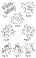
- Figures 1 to 8 are perspective views of embodiments of horizontal cavity trays according to the invention
- Figures 9 to 16 are perspective views of embodiments of parapet cavity trays according to the invention
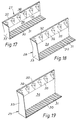
- Figures 17 to 19 are perspective views of embodiments of lintel cavity trays according to the invention
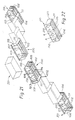
- Figures 21 and 22 are perspective views of embodiments of abutment cavity trays according to the invention
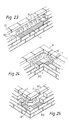
- Figures 23 to 28 show various embodiments of horizontal cavity trays according to the invention in position in a wall structure
- Figures 29 to 35 show various embodiments of parapet cavity trays according to the invention in position in a wall structure
- Figure 36 shows an embodiment of lintel cavity tray according to the invention in position in a wall structure
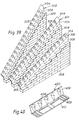
- Figure 37 shows an embodiment of abutment cavity tray according to the invention in position in a wall structure
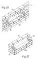
- Figure 38 shows two adjacent horizontal cavity trays in overlapping relationship
- Figure 39 shows a continuous stepped cavity tray according to the invention
- Figure 40 shows a cavity tray according to the invention for use in refurbishment work
- the rear wall portion 3 is secured to the base portion 2 along a rearward edge thereof, and is disposed at an obtuse angle thereto.
- Locating means in the form of a plurality of formations 5 are disposed upon the rear wall portion 3.
- the locating formations 5 serve to locate an adjacent cavity tray in overlapping relationship with the cavity tray 1.
- the rear wall portion 3 comprises two opposing surfaces 6 and 7.
- the formation 5 projects out of the plane of the surface 6, and forms a recess in the surface 7.
- a plurality of formations in the form of ribs 13 are provided on the base portion 2.
- the ribs 13 help to channel moisture to the front of the tray and help to prevent moisture from flowing over the ends of the tray.
- the ribs 13 may also form part of the locating means and may be arranged to engage corresponding recesses (not shown) provided in the bottom surface of the base portion 2. Also the ribs 13 help to key the cavity tray 1 into the mortar.
- Figure 2 illustrates a horizontal cavity tray 14 for use at an exterior corner of a wall
- Figure 3 illustrates a horizontal cavity tray 15 for use at an interior corner of a wall.
- Figure 4 illustrates a stepped horizontal cavity tray 16 in which the steps rise to the left
- Figure 5 illustrates a stepped horizontal cavity tray 17 in which the steps rise to the right.
- Figures 6 and 7 illustrate right and left end horizontal cavity trays 18 and 19 respectively.
- the end cavity trays 18 and 19 each include a side wall portion 4 secured to the base portion 2 and disposed at an angle of substantially 90° to the base portion.
- the side wall portions 4 are secured to the rear wall portions 3.
- Figure 8 illustrates a joining cavity tray 20 for joining two other horizontal cavity trays.
- Figure 9 illustrates a straight parapet cavity tray 21. Many of the parts of the tray 21 are similar to those shown in Figures 1 to 8 and like parts have been designated with like reference numerals.
- the tray 21 further includes a top portion 22 which extends along the upper edge of the rear wall portion 3.
- the top portion 22 is also provided with the ribs 13.
- Figures 10 to 16 illustrate parapet cavity trays similar to Figure 9 and like parts have been designated with like reference numerals.
- Figure 10 illustrates an interior parapet cavity tray 23, which can be inverted to produce an exterior parapet cavity tray, as shown in Figure 11.
- the tray 23 is inverted the top portion 22 is transformed into the base portion 2 and vice versa.
- Figure 12 illustrates a stepped parapet cavity tray 24 in which the steps rise to the right. This can be inverted to produce a stepped parapet cavity tray 24 in which the steps rise to the left, as shown in Figure 13. Again, when the tray 24 is inverted the top portion 22 is transformed into the base portion and vice versa.
- Figures 14 and 15 illustrate right and left end parapet cavity trays 25 and 26 respectively.
- Figure 16 illustrates a joining parapet cavity tray 40 for joining two other parapet cavity trays.
- FIGS 17 to 19 illustrate three embodiments of lintel cavity trays designated 27, 28 and 29 respectively.
- Each of the lintel cavity trays 27, 28 and 29 comprises a base portion 30 provided with ribs 31 which are similar to the ribs 13.
- a rear wall portion 32 is provided along the rear edge of the base portion 30.
- a side wall portion 33 is secured at one end of the tray 27, 28 or 29 to both the base portion 30 and the rear wall portion 32.
- a further side wall portion (not shown) may be provided at the other end of the tray 27, 28 or 29.
- the rear wall portion 32 comprises a first part 34 which extends substantially at right angles from the base portion 30, and a second part 35 which is disposed at an angle to the first part 34.
- Locating means in the form of formations 36 are provided in the second part 35.
- the formations 36 are similar to the formations 5.
- the principal difference between the trays 27, 28 and 29 resides in the length of the first part 34.
- abutment cavity tray is shown in Figure 21.
- tray There are two types of tray shown in this Figure: one type are intermediate trays 200, and the other type are end trays 201. Some of the trays 200 and 201 are shown only in outline.
- the tray 200 comprises a cavity member which includes a base portion 102, a rear wall portion 103 and a side wall portion 104.
- the rear wall portion 103 is secured to the base portion 102 and is disposed at an obtuse angle thereto.
- the side wall portion 104 is secured to the base portion 102 and to the rear wall portion 103; the side wall portion 104 is disposed at substantially 90° to the base portion 102.
- a plurality of elongate formations 105 are provided on the side wall portion 104 and the base portion 102, and extend substantially parallel to the longitudinal axis of the base portion 102.
- the formations 105 assist with securing the base portion 102 and the sidewall portion 104 to a wall.
- Locating means in the form of formations 202 are provided on the rear portion 103.
- the formations 202 are similar to the formations 5.
- the front of the base portion 102 may be provided with a rebate (not shown) which serves for securing lead flashing to the cavity tray 101.
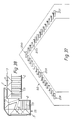
- the cavity tray 200 also includes drainage means comprising a drainage channel 107 provided in the base portion 102.
- the drainage channel 107 includes a first portion (not shown) and a second portion 109 extending substantially transverse thereto.
- the first portion of the drainage channel 107 extends substantially transverse to the longitudinal axis of the base portion 102 beneath a cover 111, while the second portion 109 of the drainage channel 107 extends substantially parallel to the longitudinal axis of the base portion 102, and is disposed adjacent to the rear wall portion 103.
- the second portion 109 is arranged at a small acute angle to the plane of the base portion 102.
- the cover 111 provided for covering the first portion of the drainage channel 107 prevents the first portion from becoming blocked up, for example, with mortar.
- the cover 111 is connected to the base portion 102 via a hinge 112 which enables the cover to pivot between a position in which it does not cover the first portion of the channel 107 (not shown), and a position in which it does cover the first portion 108 (as shown).
- the cover 111 extends slightly beyond the forward edge of the base portion 102.
- the cover 111 is slightly larger than the thickness of the first wall.
- Overflow means (not shown) is provided adjacent the intersection of the first portion and the second portion 109 of the drainage channel 107.
- the overflow allows the drainage of excess moisture, when the drainage channel 107 can accommodate no further moisture.
- the overflow means also includes a drip channel for collecting moisture falling over the overflow 113.
- side wall portion 104 can be provided at the opposite end of the base portion 102 to that shown in Figure 5.
- the rear wall portion 103 is provided with a strengthening formation 115 disposed at the end remote from the side wall 104.
- the base portion 102 is provided with depressions 116 which extend to the level of the first channel portion 108; the depressions 116 form feet for the cavity tray 101.
- the trays 201 are similar to the trays 200 and like parts are designated with like reference numerals. The principal difference is the provision of another side wall portion 104.
- the drainage means is disposed substantially centrally of the base portion 102.
- abutment cavity tray is designated 210 in Figure 22.
- the abutment tray 210 comprises a base portion 211 from which a rear wall portion 212 extends at an obtuse angle.
- Side walls 213 and 214 are provided at opposite ends of the tray 210.
- the height of the side walls 213 and 214 is less than the height of the rear wall portion 212.
- Ribs 215 (similar to ribs 13) are provided on the base portion 211 and formations 216 (similar to formations 5) are provided on the rear wall portion 212.
- the tray 210 can be used as an end abutment cavity tray. However it also has other uses.
- the tray 210 can be cut along dotted line B to provide a right and left hand short abutment cavity tray.
- the tray 210 can be cut along dotted line A to provide a medium length abutment cavity tray.
- the side wall 214 can be removed in order to provide a long abutment cavity tray. Thus, only one moulding is required to produce several different abutment cavity trays.
- FIGS 23 to 36 various embodiments of the horizontal, parapet and lintel cavity trays are shown positioned in a wall structure comprising a first wall 50 and a second wall 51.
- the location formations 5 form an abutment against which the bricks of the wall 50 can be placed during the construction thereof. This helps with the correct positioning of the bricks in the wall 50.
- the locating formations of the other embodiments of cavity trays can also perform this function.
- Figure 37 shows a plurality of abutment cavity trays 200 and 201 in a gable abutment of a pitched roof structure 52.
- Figure 38 shows the interior horizontal cavity tray 15 in overlapping relationship with the straight horizontal cavity tray 1, and slightly separated from one another.
- FIG 39 shows three continuous stepped cavity trays 300, 301 and 302, each positioned on a wall 306.
- Each tray 300, 301 and 302 comprises a base portion 303 having a rear wall portion 304 extending at an obtuse angle thereto.
- Formations 305 are provided on the rear wall portion 304. Ribs (not shown), which are similar to the ribs 13 can be provided on the base portion 303.
- the trays 300, 301 and 302 are arranged at angles of about 20°, 30° and 45° respectively to the horizontal.
- Figure 40 shows a horizontal cavity tray 400 for use in refurbishment work.
- the tray comprises a base portion 401 and a rear wall portion 402 extending at an obtuse angle thereto.
- the base portion 401 is provided with ribs 403, similar to the ribs 13), and the rear wall portion is provided with formations 404, similar to the formations 5.
- the length of the tray 400 is typically two and one half bricks.
- the tray 400 is fitted into a course of bricks in an existing wall in the following manner. Firstly, three adjacent bricks in the course are removed and the tray 400 is inserted in the course. Two bricks are then placed back in the course on the tray 400, and a further two bricks are removed. Another tray 400 is then placed in the course next to the first tray 400. This procedure can be repeated until the entire course has been fitted with the cavity trays 400.
Landscapes
- Engineering & Computer Science (AREA)
- Architecture (AREA)
- Civil Engineering (AREA)
- Structural Engineering (AREA)
- Physics & Mathematics (AREA)
- Electromagnetism (AREA)
- Finishing Walls (AREA)
- Washing And Drying Of Tableware (AREA)
Claims (10)
- Hohlraumprofil (1) zur Anwendung in einer Wandstruktur mit einer ersten und einer zweiten, voneinander beabstandeten und einen Hohlraum zwischen sich bildenden Wand (50, 51), das zum Aufsammeln von Feuchtigkeit in dem Hohlraum ausgebildet ist und ein Hohlteil mit einem Basisschenkel (2), der zur Anordnung in der ersten Wand (50) ausgebildet ist, und einen Rückschenkel (3) aufweist, der entlang der Längserstreckung des Hohlraumprofils mit dem Basisschenkel verbunden ist und in den Hohlraum vorsteht, dadurch gekennzeichnet, daß an dem Hohlteil mindestens eine Gestaltungsstelle (5) vorgesehen ist, daß die oder jede Gestaltungsstelle (5) zum Zusammenwirken mit einer entsprechenden Anordnungsstelle an einem benachbarten Hohlraumprofil ausgebildet ist, um das Hohlraumprofil mit festgelegter Überlappung in Längsrichtung relativ zu dem benachbarten Hohlraumprofil zu plazieren.
- Hohlraumprofil nach Anspruch 1, dadurch gekennzeichnet, daß die oder jede Gestaltungsstelle (5) zugleich der Festlegung dient, um das Hohlraumprofil und das benachbarte Hohlraumprofil in der überlappenden Relativlage zu halten.
- Hohlraumprofil nach Anspruch 1 oder 2, dadurch gekennzeichnet, daß die oder jede Gestaltungsstelle (5) auf der einen Seite des Hohlprofils einen Vorsprung und auf der anderen Seite eine Vertiefung bildet.
- Hohlraumprofil nach einem der vorangehenden Ansprüche 1 bis 3, dadurch gekennzeichnet, daß der Rückschenkel am Basisschenkel unter Einschluß eines stumpfen Winkels angeordnet ist.
- Hohlraumprofil nach einem der vorangehenden Ansprüche 1 bis 4, dadurch gekennzeichnet, daß die oder jede Gestaltungsstelle (5) am Rückschenkel (3) und/oder am Basisschenkel (2) angeordnet ist.
- Hohlraumprofil nach Anspruch 5, dadurch gekennzeichnet, daß für den Fall, daß die oder jede Gestaltungsstelle (5) am Basisschenkel (2) und am Rückschenkel (3) vorgesehen sind, die oder jede Gestaltungsstelle am Rückschenkel in festgelegter Relativlage zu der oder jede Gestaltungsstelle am Basisschenkel angeordnet sind.
- Hohlraumprofil nach einem der vorangehenden Ansprüche 1 bis 6, dadurch gekennzeichnet, daß der Basisschenkel eine das Übertreten von Feuchtigkeit über seine Enden verhindernde Formgebung aufweist und zumindest in seinen Endbereichen Rippen oder Wellen trägt.
- Hohlraumprofil nach Anspruch 7, dadurch gekennzeichnet, daß die Rippen oder Wellen zugleich als Gestaltungsstellen ausgebildet sind.
- Hohlraumprofil nach einem der vorangehenden Ansprüche 1 bis 8, dadurch gekennzeichnet, daß beim Einsatz die Gestaltungsstellen (5) mit der ersten Wand (50) in Wirkkontakt treten, um den Rückschenkel (3) auf Abstand zu der ersten Wand (50) zu bringen.
- Hohlraumprofil nach einem der vorangehenden Ansprüche 1 bis 9, dadurch gekennzeichnet, daß die Gestaltungsstellen (5) in einer Reihe entlang am Rückschenkel (3) angeordnet sind.
Priority Applications (1)
| Application Number | Priority Date | Filing Date | Title |
|---|---|---|---|
| AT87303310T ATE64640T1 (de) | 1986-04-15 | 1987-04-15 | Sturzprofil. |
Applications Claiming Priority (4)
| Application Number | Priority Date | Filing Date | Title |
|---|---|---|---|
| GB868609174A GB8609174D0 (en) | 1986-04-15 | 1986-04-15 | Cavity tray |
| GB8609174 | 1986-04-15 | ||
| GB868609172A GB8609172D0 (en) | 1986-04-15 | 1986-04-15 | Cavity tray |
| GB8609172 | 1986-04-15 |
Publications (2)
| Publication Number | Publication Date |
|---|---|
| EP0243079A1 EP0243079A1 (de) | 1987-10-28 |
| EP0243079B1 true EP0243079B1 (de) | 1991-06-19 |
Family
ID=26290628
Family Applications (1)
| Application Number | Title | Priority Date | Filing Date |
|---|---|---|---|
| EP19870303310 Expired EP0243079B1 (de) | 1986-04-15 | 1987-04-15 | Sturzprofil |
Country Status (3)
| Country | Link |
|---|---|
| EP (1) | EP0243079B1 (de) |
| DE (1) | DE3770860D1 (de) |
| GB (1) | GB2189275B (de) |
Families Citing this family (16)
| Publication number | Priority date | Publication date | Assignee | Title |
|---|---|---|---|---|
| EP0387043A1 (de) * | 1989-03-08 | 1990-09-12 | Tbp Industries Limited | Wandsturzprofil |
| GB2234762B (en) * | 1989-07-25 | 1993-12-01 | Knox Colin J M | Cavity tray system |
| DE69007053T2 (de) * | 1989-12-29 | 1994-09-29 | Weldform Components Ltd | Sturzprofil. |
| US5819478A (en) * | 1994-03-14 | 1998-10-13 | D. Anderson And Son Limited | Damp-proof course member |
| DK173989B1 (da) * | 1998-04-07 | 2002-03-25 | Vkr Holding As | Inddækningselement og -ramme til taggennembrydende bygningsdel |
| NL1016326C2 (nl) * | 2000-10-04 | 2001-08-28 | Ronald Bernardus Theodorus Mar | 'SPAF' Prefab afwateringssysteem in buitenmuren, uitgevoerd in E.P.D.M. rubberfolie. |
| GB2371568B8 (en) * | 2001-01-24 | 2005-07-01 | Jack Hamer & Son Tottington Lt | Cavity wall tray |
| GB0211371D0 (en) | 2002-05-17 | 2002-06-26 | Ayers Charles W J | Improvements in or relating to a spacer device for a cavity wall |
| GB2405162B (en) * | 2002-05-17 | 2006-03-15 | Surecav Ltd | Further improvements in or relating to a spacer device for a cavity wall |
| US7543414B2 (en) * | 2005-06-06 | 2009-06-09 | Tom Sourlis | Drainage system for use in building construction |
| IE20080542A1 (en) * | 2007-07-02 | 2009-06-24 | Mary Margaret Byrne | A moisture barrier, and a method for minimising the passage of moisture from a concrete roof barge element to an inner leaf of a wall of a building |
| GB2509767A (en) * | 2013-01-15 | 2014-07-16 | Daniel Cooper | Damp proof course, cavity tray, flashing or lintel with protruding regions |
| GB2516466B (en) * | 2013-07-23 | 2017-03-15 | Cavity Trays Ltd | Cavity wall component with drainage |
| GB201918961D0 (en) * | 2019-10-22 | 2020-02-05 | Keyfix Ltd | A barrier for providing insulation and/or preventing the spread of fire |
| GB2588649B (en) * | 2019-10-30 | 2021-11-10 | Acs Stainless Steel Fixings Ltd | Cavity tray system |
| GB202014450D0 (en) * | 2020-09-14 | 2020-10-28 | Keyfix Ltd | Cavity tray |
Family Cites Families (10)
| Publication number | Priority date | Publication date | Assignee | Title |
|---|---|---|---|---|
| US2245965A (en) * | 1940-02-10 | 1941-06-17 | Cunin Hyman | Lintel |
| US2292459A (en) * | 1940-04-13 | 1942-08-11 | Raymond J Martin | Building construction |
| GB1007225A (en) * | 1963-05-14 | 1965-10-13 | Eric Reginald Shillabeer | Wall cavity gutter or tray |
| GB1086226A (en) * | 1965-05-04 | 1967-10-04 | Pearl Brenda Shillabeer | Cavity gutters or trays |
| GB1486125A (en) * | 1976-03-15 | 1977-09-21 | Timpak Ltd | Damp-proof courses for brick or block walls |
| GB1486532A (en) * | 1976-03-19 | 1977-09-21 | Timpak Ltd | Damp-proof courses for brick or block walls |
| GB2025798B (en) * | 1978-07-19 | 1982-10-06 | Clark F | Sheet metal box lintel |
| GB2103680B (en) * | 1981-08-07 | 1985-04-11 | Press Bat Holdings Ltd | Lintel and wall comprising same |
| GB2118585B (en) * | 1982-03-11 | 1985-12-18 | Jones And Son Frederick | Cavity-wall lintel combined with damp-proof course |
| GB2142359B (en) * | 1983-06-28 | 1986-12-17 | John Louis Shillabeer | Cavity tray |
-
1987
- 1987-04-14 GB GB8708978A patent/GB2189275B/en not_active Expired - Lifetime
- 1987-04-15 DE DE8787303310T patent/DE3770860D1/de not_active Expired - Fee Related
- 1987-04-15 EP EP19870303310 patent/EP0243079B1/de not_active Expired
Also Published As
| Publication number | Publication date |
|---|---|
| GB2189275A (en) | 1987-10-21 |
| DE3770860D1 (de) | 1991-07-25 |
| GB8708978D0 (en) | 1987-05-20 |
| GB2189275B (en) | 1990-08-15 |
| EP0243079A1 (de) | 1987-10-28 |
Similar Documents
| Publication | Publication Date | Title |
|---|---|---|
| EP0243079B1 (de) | Sturzprofil | |
| JPH0359219B2 (de) | ||
| JPH11508339A (ja) | 平らな板状の建築要素のための下張り要素 | |
| JPS5826268Y2 (ja) | 外壁材 | |
| JPH072849Y2 (ja) | 断熱用瓦下地材 | |
| JPH0145288Y2 (de) | ||
| JPS6318685Y2 (de) | ||
| JP3660786B2 (ja) | 雨どいの接続構造 | |
| JPS6039393Y2 (ja) | ひさし用水抜き具 | |
| JPS588810Y2 (ja) | アマキリガワラ | |
| JPH0629329Y2 (ja) | 横葺用屋根材の葺き構造 | |
| JPS5849298Y2 (ja) | 二段雨切り瓦 | |
| JPS601139Y2 (ja) | 樋装置 | |
| JPH027125Y2 (de) | ||
| JPS63916Y2 (de) | ||
| JPH032573Y2 (de) | ||
| JPS6015792B2 (ja) | 建築物の横葺き外壁、屋根 | |
| JPS5850010Y2 (ja) | 屋根構造 | |
| JPS5823870Y2 (ja) | 合成樹脂製床板 | |
| JPS6237864Y2 (de) | ||
| JPS6210332Y2 (de) | ||
| JPH0629328Y2 (ja) | 横葺用屋根材の葺き構造 | |
| JPH0539125Y2 (de) | ||
| JPH0217057Y2 (de) | ||
| JPH032574Y2 (de) |
Legal Events
| Date | Code | Title | Description |
|---|---|---|---|
| PUAI | Public reference made under article 153(3) epc to a published international application that has entered the european phase |
Free format text: ORIGINAL CODE: 0009012 |
|
| AK | Designated contracting states |
Kind code of ref document: A1 Designated state(s): AT BE CH DE ES FR GB GR IT LI LU NL SE |
|
| 17P | Request for examination filed |
Effective date: 19880425 |
|
| 17Q | First examination report despatched |
Effective date: 19890213 |
|
| GRAA | (expected) grant |
Free format text: ORIGINAL CODE: 0009210 |
|
| AK | Designated contracting states |
Kind code of ref document: B1 Designated state(s): AT BE CH DE ES FR GB GR IT LI LU NL SE |
|
| PG25 | Lapsed in a contracting state [announced via postgrant information from national office to epo] |
Ref country code: IT Free format text: LAPSE BECAUSE OF FAILURE TO SUBMIT A TRANSLATION OF THE DESCRIPTION OR TO PAY THE FEE WITHIN THE PRE;WARNING: LAPSES OF ITALIAN PATENTS WITH EFFECTIVE DATE BEFORE 2007 MAY HAVE OCCURRED AT ANY TIME BEFORE 2007. THE CORRECT EFFECTIVE DATE MAY BE DIFFERENT FROM THE ONE RECORDED.SCRIBED TIME-LIMIT Effective date: 19910619 Ref country code: NL Effective date: 19910619 Ref country code: GR Free format text: LAPSE BECAUSE OF FAILURE TO SUBMIT A TRANSLATION OF THE DESCRIPTION OR TO PAY THE FEE WITHIN THE PRESCRIBED TIME-LIMIT Effective date: 19910619 Ref country code: LI Effective date: 19910619 Ref country code: CH Effective date: 19910619 Ref country code: BE Effective date: 19910619 Ref country code: AT Effective date: 19910619 Ref country code: SE Effective date: 19910619 |
|
| REF | Corresponds to: |
Ref document number: 64640 Country of ref document: AT Date of ref document: 19910715 Kind code of ref document: T |
|
| REF | Corresponds to: |
Ref document number: 3770860 Country of ref document: DE Date of ref document: 19910725 |
|
| PG25 | Lapsed in a contracting state [announced via postgrant information from national office to epo] |
Ref country code: ES Free format text: LAPSE BECAUSE OF FAILURE TO SUBMIT A TRANSLATION OF THE DESCRIPTION OR TO PAY THE FEE WITHIN THE PRESCRIBED TIME-LIMIT Effective date: 19910930 |
|
| REG | Reference to a national code |
Ref country code: CH Ref legal event code: PL |
|
| EN | Fr: translation not filed | ||
| PG25 | Lapsed in a contracting state [announced via postgrant information from national office to epo] |
Ref country code: FR Effective date: 19911108 |
|
| NLV1 | Nl: lapsed or annulled due to failure to fulfill the requirements of art. 29p and 29m of the patents act | ||
| PLBE | No opposition filed within time limit |
Free format text: ORIGINAL CODE: 0009261 |
|
| STAA | Information on the status of an ep patent application or granted ep patent |
Free format text: STATUS: NO OPPOSITION FILED WITHIN TIME LIMIT |
|
| PG25 | Lapsed in a contracting state [announced via postgrant information from national office to epo] |
Ref country code: LU Free format text: LAPSE BECAUSE OF NON-PAYMENT OF DUE FEES Effective date: 19920430 |
|
| 26N | No opposition filed | ||
| REG | Reference to a national code |
Ref country code: FR Ref legal event code: ST |
|
| PGFP | Annual fee paid to national office [announced via postgrant information from national office to epo] |
Ref country code: GB Payment date: 19970407 Year of fee payment: 11 |
|
| PGFP | Annual fee paid to national office [announced via postgrant information from national office to epo] |
Ref country code: DE Payment date: 19970418 Year of fee payment: 11 |
|
| PG25 | Lapsed in a contracting state [announced via postgrant information from national office to epo] |
Ref country code: GB Free format text: LAPSE BECAUSE OF NON-PAYMENT OF DUE FEES Effective date: 19980415 |
|
| GBPC | Gb: european patent ceased through non-payment of renewal fee |
Effective date: 19980415 |
|
| PG25 | Lapsed in a contracting state [announced via postgrant information from national office to epo] |
Ref country code: DE Free format text: LAPSE BECAUSE OF NON-PAYMENT OF DUE FEES Effective date: 19990202 |