EP0242786A2 - Dispositif pour mesurer un produit fluide - Google Patents
Dispositif pour mesurer un produit fluide Download PDFInfo
- Publication number
- EP0242786A2 EP0242786A2 EP87105596A EP87105596A EP0242786A2 EP 0242786 A2 EP0242786 A2 EP 0242786A2 EP 87105596 A EP87105596 A EP 87105596A EP 87105596 A EP87105596 A EP 87105596A EP 0242786 A2 EP0242786 A2 EP 0242786A2
- Authority
- EP
- European Patent Office
- Prior art keywords
- rotary valve
- connecting sleeve
- drive
- piston rod
- designed
- Prior art date
- Legal status (The legal status is an assumption and is not a legal conclusion. Google has not performed a legal analysis and makes no representation as to the accuracy of the status listed.)
- Granted
Links
Images

Classifications
-
- B—PERFORMING OPERATIONS; TRANSPORTING
- B65—CONVEYING; PACKING; STORING; HANDLING THIN OR FILAMENTARY MATERIAL
- B65B—MACHINES, APPARATUS OR DEVICES FOR, OR METHODS OF, PACKAGING ARTICLES OR MATERIALS; UNPACKING
- B65B3/00—Packaging plastic material, semiliquids, liquids or mixed solids and liquids, in individual containers or receptacles, e.g. bags, sacks, boxes, cartons, cans, or jars
- B65B3/26—Methods or devices for controlling the quantity of the material fed or filled
- B65B3/30—Methods or devices for controlling the quantity of the material fed or filled by volumetric measurement
- B65B3/32—Methods or devices for controlling the quantity of the material fed or filled by volumetric measurement by pistons co-operating with measuring chambers
Definitions
- the invention relates to a device for dimensioning a flowable product, which is filled from a storage container into a packaging unit, with a rotary valve mounted rotatably in a housing and designed as a measuring container, which encloses a cavity provided with an opening, the opening of which opens when the cavity is filled the product-containing storage container faces, while when the cavity is emptied after a rotation of the rotary valve, it faces the packaging unit.
- the object of the present invention is therefore to improve the device of the type mentioned in the introduction so that it has a relatively high wear resistance.
- rotary slide valve is fixedly connected at its end opposite the opening to a drive coupling which engages with a rotary motion executing drive.
- the drive coupling is designed as a drive sleeve which is firmly connected to the end.
- This drive sleeve has the advantage that its cross section can be adapted to that of the rotary valve. In this way it can be achieved with cheap and simple means that the forces required for rotating the rotary slide valve can be introduced into the rotary slide valve at a point as far out as possible. In this way, relatively small forces are sufficient to generate the torque required to rotate the rotary valve.
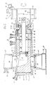
- a device consists essentially of a housing (1), a rotary valve (2) and a piston head (3).
- the rotary valve (2) is guided with a tight fit 4 in an interior (5) which is formed within the housing (1).
- the rotary valve (2) is both rotatable about its longitudinal axis and slidable in the axial direction. Storage takes place on an outer surface (6) of the rotary valve (2) facing the housing (1), which slidably acts on an inner surface (7) of the housing (1) opposite it, which delimits the interior (5).
- the rotary valve (2) is designed as a measuring container, in the interior of which a cavity (8) is provided.
- This cavity (8) extends in the axial direction of the rotary valve (2) and is approximately cylindrical.
- the piston head (3) slides in the axial direction, to which a piston rod (9) is attached, which protrudes with its end (10) opposite the piston head (3) from the rotary valve (2).
- This is closed at its end (10) of the piston rod (9) adjacent end (12) by a wall (11) which is penetrated by an opening (13).
- the piston rod (9) is guided in this opening (13).
- This has a round or square cross section, so that the opening (13) also has a corresponding cross section.
- a coupling device (15) is provided at the end (10) of the piston rod (9), to which a drive (not shown) which moves the piston rod (9) can be coupled.
- This coupling device (15) is designed as a bore which penetrates the piston rod (9) transversely to the longitudinal direction thereof.
- annular groove (16) is let into the wall (11), the mutually opposite walls of which extend in the radial direction are designed as sliding surfaces (17, 18).
- a coupling (19) slides on these sliding surfaces (17, 18), which is connected to a drive, not shown, which is capable of displacing the rotary valve (2) in the axial direction.
- the end of the rotary slide (2) protrudes (12) from a rear part (20) of the housing (1).
- the groove (16) is provided on this end (12) protruding from the housing (1).
- the outer surface (6) tapers towards its opposite front end (21) in such a way that the cross sections taper from the rear end (12) towards the front end (21).
- the inner surface (7) of the interior (5) is conical, so that it has its largest cross section in the area of its rear part (20).
- the cavity (8) is designed as a cleaning chamber (22) at its end adjacent to the wall (11). This has a larger cross section than a front part (21) facing cylinder part (23), the cross section of which is dimensioned such that the piston head (3) sliding in it is guided with such a close fit that it is capable of depending to generate a negative or positive pressure within the cylinder part (23) according to the direction of movement.
- the piston head (3) carries at its end adjacent to the piston rod (9) a piston sleeve (24), which with its outer surface (25) ensures a pressure-tight seal of the piston head (3) within the cavity (8).
- a transition zone (26) is provided between the cleaning chamber (22) and the cylinder part (23), in which the cross section of the cylinder part (23) continually widens to the cross section of the cleaning chamber (22).
- Access openings (27) for a cleaning liquid are provided in the cleaning chamber (22) and are supplied via a cleaning connection (28).
- This cleaning connection (28) extends through the housing (1) into the interior (5).
- a further cleaning connection (33) is provided on a front end (34) of the housing (1) which is adjacent to the front end (21). This cleaning connection (33) is aligned with an access opening (35) which opens into the interior (5) in the region of the front end (21).
- a further cleaning connection (36) is provided in the area of an inlet (37) through which a product to be filled is passed through a bore (38) into the housing (1) and from there via an opening (39) into the cylinder part (23). of the cavity (8) occurs.
- the inlet (37) can be designed as a pipeline which is fixedly connected to a correspondingly designed flange which surrounds the bore (38) and is fixedly connected to the housing (1).
- the housing (1) is provided at its front end (34) with a bore (41), the cross section of which is smaller than that of the interior (5) adjacent to it.
- This bore (41) is closed by a cap (42) which is guided with a collar in the bore (41).
- a bearing journal (44) adjoins this collar in the direction of the interior (5), the cross section of which corresponds to the cross section of the cylinder part (23) into which the bearing journal (44) projects.
- the rotary slide valve (2) is guided in the region of its front end (21) on this bearing journal (44).
- This cap (42) is delimited on its outside facing away from the bearing journal (44) by a cover surface which projects beyond the collar and closes the bore (41) in a pressure-tight manner.
- the interior (5) has an outlet bore (46) which is opposite the bore (38) by an angle of rotation of approximately 180 ° with respect to the housing (1).
- This outlet bore (46) is aligned with the opening (39) of the rotary valve (2) and thus with the bore (38). It opens into a mouthpiece (47), for example, immediately above a packaging unit to be filled a cup (48) is arranged.
- This cup (48) is transported with the aid of a conveyor device (49), for example a conveyor belt, in the direction of the mouthpiece (47) or is conveyed away therefrom.
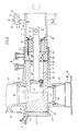
- connection sleeve (70) is firmly connected to the wall (11) by means of screws (71) which protrude through a flange (72) facing the wall (11) into screw holes (73) provided in the wall (11) . With the aid of the screws (71), the flange (72) facing the wall (11) is firmly screwed.
- the connecting sleeve (70) extends in a direction facing away from the front end (21) and is designed as a piece of pipe to which a rotary drive (75) for the rotary slide valve (2) is connected.
- This rotary drive (75) can be designed, for example, as a pinion (76) which is fastened, for example shrunk, onto a surface (74) of the tubular connecting sleeve (70).
- This pinion (76) has a relatively large width which is larger than that of a drive gear (77) which is in engagement with the pinion (76).
- This drive gear (77) is fastened to a drive shaft (78) which is driven by an electric motor (79).
- the comparatively large width of the pinion (76) compared to the drive gear (77) allows the connecting sleeve (70) to be displaced in its longitudinal direction without the drive gear (77) therefore becoming disengaged from the pinion (76).
- the connecting sleeve (70) has a relatively large inner diameter (80).
- One of a wall corresponds to it (81) of the connecting sleeve (70) spanned interior (82) into which the piston rod (9) protrudes with its end (10).
- a drive (not shown) which moves the piston rod can be brought into engagement with the coupling device (15) inside the interior (82).
- the connector sleeve (70) is enclosed on its surface (74) by the coupling (19) with little play. With the help of this coupling (19), both the rotary valve (2) and the connecting sleeve (70) connected to it can be moved in their longitudinal directions.
- the product to be filled for example a milk product interspersed with solid components
- the inlet (37) in the direction of the bore (38) and the opening (39), which during the filling of the cylinder part (23) with the Hole (38) is aligned.
- the product is sucked in that the piston head (3) is moved in the direction of the cleaning chamber (22) and a negative pressure is generated in the cylinder part (23). The movement of the piston head comes to an end before it reaches the cleaning chamber (22).
- the electric motor (79) which can be a stepping motor, is switched on, which via the drive gear (77) and the pinion (66) connects the connecting sleeve (70) and thus the rotary valve (2) through an angle of 180 ° twisted.
- the opening (39) reaches the area of the outlet bore (46).
- the piston head (3) is moved towards the front end (21) and the product contained in the cylinder part (23) through the outlet bore (46) towards the Ejected cup (48).
- the rotary slide valve (2) is rotated about its central axis until the opening (39) is aligned with the bore (38). In this position, the product can enter the opening (39).
- the piston head (3) is moved in the direction of the cleaning chamber (22), so that a vacuum is now created in a part of the cylinder part (23) which is adjacent to the front end (21) and which pushes the product into the cylinder part (23 ) sucks.
- the rotary valve (2) is pulled out of the snug fit (4) in the direction of its rear end (12) with the aid of the coupling (19).
- a relatively small displacement of the rotary valve (2) is sufficient.
- the drive gear (77) slides by the size of this displacement through the teeth of the pinion (76) which are in engagement with it.
- This displacement is sufficient to loosen the seat of the rotary slide valve (2) within the interior (5) to such an extent that, due to the conical shape of both the inner surface (7) and the outer surface (6), that a through the cleaning connections (28 ) and (33) entering cleaning liquid between the outer surface (6) on the one hand and the inner surface (7) on the other.
- the cleaning liquid passes through the cleaning connection (33) into the region of the front end (21) of the rotary slide valve (2), so that it is also cleaned to the desired extent.
- the cleaning liquid enters through the cleaning connection (33) both via the collar (44) into the cavity (8) and via the outer surface (6) into the opening (39).
- cleaning liquid gets through the cleaning connection (36) into the Inlet (37) and thus into the cavity (8).
- the piston head (3) is pulled back into the cleaning chamber (22), so that it is washed around on all sides by the cleaning liquid that enters through the access opening (27).
- the cross section of the cleaning chamber (22) is selected so that the piston head (3) does not rest on its inner walls when it is drawn into it.
- the piston head (3) is flushed on all sides with cleaning agent, which leaves the cleaning chamber (22) via an outlet opening (50) which is provided in the rotary valve (2) and is aligned with a drain opening (51) which is in the housing (1 ) is provided and emerges from the cleaning liquid in the direction of a collecting container, not shown.
- the cleaning process is ended.
- the supply of cleaning fluid to the cleaning connections (28, 33, 36) is interrupted and the rotary valve (2) is moved in the axial direction onto the front end (21) by means of the coupling (19), so that the tight fit ( 4) is restored.
- the filling of the cups (48) can be resumed, which are transported up to the conveyor (49).
- the connecting sleeve (70) it is also possible, via the connecting sleeve (70), to introduce the forces necessary for displacing the rotary slide valve (2) directly into the latter.
- the coupling (19) can be omitted.
- the connecting sleeve (70) is connected directly to the rotary valve (2) via an intermediate piece (83) by means of the screws (71).
- the spacer (83) only serves to receive a sliding bush (84) in which the opening (13) is provided for mounting the piston rod (9).
- a drive (85) for displacing the rotary valve (2) in its longitudinal direction is attached to the surface (74) in addition to the rotary drive (75), which is not shown in FIG. 2.
- This displacement drive (85) consists essentially of a ring (86) which is fixed immovably on the surface (74) in the longitudinal direction of the connecting sleeve (70), for example shrunk on.
- This ring (86) is rotatably supported relative to a driver (87) which can only perform movements in the longitudinal direction of the connecting sleeve (70), but not rotary movements.
- the rotatable mounting of the driver (87) relative to the ring (86) can take place, for example, with the aid of a deep groove ball bearing (88) which transfers the forces required to move the rotary valve (2) from the driver (87) to the ring (86).
- a deep groove ball bearing (88) which transfers the forces required to move the rotary valve (2) from the driver (87) to the ring (86).
- the driver can, for example, be designed as a sliding sleeve (89) extending in the longitudinal direction of the connecting sleeve parallel to its surface (74), which is provided at its end facing the ring (86) with a groove (90) receiving the ring (86) , in which the ring (86) is rotatably mounted.
- a rack (91) extending in the longitudinal direction of the connecting sleeve (70), for example, can be fastened to the sliding sleeve (89) and a toothed pinion (92) driven by a drive motor (not shown) engages in the teeth thereof.
- the pinion (92) moved in one direction or the other. It takes the rack (91) and thus the ring (86) with it, via which the rotary slide (2) is either pulled into the cleaning position or pushed out of this back into the filling position.
- the intermediate piece (83) is also possible to connect the intermediate piece (83) directly to the connecting sleeve (70) so that it is connected directly to the rotary slide valve (2) via the screws (71).
- the connecting sleeve (70) is provided at its end facing the rotary valve (2) with a flange (93) through which the screws (71) protrude into the rotary valve (2).
- This flange (93) bears directly on a radially extending support surface (94) provided on the rotary slide valve (2).
- the flange (93) serves to receive the slide bush (84) in which the piston rod (9) is mounted.
- connection of the connecting sleeve (70) to the rotary valve (2) is aimed at a short, compact construction which allows the rotary actuator (75) as well as the sliding actuator (85) to be arranged at a point as close as possible to the rotary valve ( 2) lies.
- the connection of the connecting sleeve (70) with the rotary valve (2) is selected so that the torques necessary for rotating the rotary valve (2) are introduced into the rotary valve (2) at one point, as far as possible on the outer circumference of the rotary valve (2).
- the piston rod (9) can have any cross section, for example a circular or angular cross section.
- the choice of a circular cross section is advisable since it allows a cheap and simple design of the slide bush (84).
- Warehousing of the rotary valve (2) is carried out on a bearing bush (52) both for the purpose of executing rotary movements and of axial movements.
Landscapes
- Engineering & Computer Science (AREA)
- Mechanical Engineering (AREA)
- Basic Packing Technique (AREA)
- Detergent Compositions (AREA)
- Agricultural Chemicals And Associated Chemicals (AREA)
- Polyesters Or Polycarbonates (AREA)
- Sampling And Sample Adjustment (AREA)
- Reciprocating Pumps (AREA)
- Processing And Handling Of Plastics And Other Materials For Molding In General (AREA)
Priority Applications (1)
| Application Number | Priority Date | Filing Date | Title |
|---|---|---|---|
| AT87105596T ATE91985T1 (de) | 1986-04-19 | 1987-04-15 | Vorrichtung zur abmessung eines fliessfaehigen produktes. |
Applications Claiming Priority (2)
| Application Number | Priority Date | Filing Date | Title |
|---|---|---|---|
| DE3613266 | 1986-04-19 | ||
| DE19863613266 DE3613266A1 (de) | 1986-04-19 | 1986-04-19 | Vorrichtung zur abmessung eines fliessfaehigen produktes |
Publications (3)
| Publication Number | Publication Date |
|---|---|
| EP0242786A2 true EP0242786A2 (fr) | 1987-10-28 |
| EP0242786A3 EP0242786A3 (en) | 1988-09-07 |
| EP0242786B1 EP0242786B1 (fr) | 1993-07-28 |
Family
ID=6299064
Family Applications (1)
| Application Number | Title | Priority Date | Filing Date |
|---|---|---|---|
| EP87105596A Expired - Lifetime EP0242786B1 (fr) | 1986-04-19 | 1987-04-15 | Dispositif pour mesurer un produit fluide |
Country Status (6)
| Country | Link |
|---|---|
| US (1) | US4867351A (fr) |
| EP (1) | EP0242786B1 (fr) |
| AT (1) | ATE91985T1 (fr) |
| CA (1) | CA1279045C (fr) |
| DE (2) | DE3613266A1 (fr) |
| DK (1) | DK189287A (fr) |
Cited By (1)
| Publication number | Priority date | Publication date | Assignee | Title |
|---|---|---|---|---|
| WO2011085709A1 (fr) | 2010-01-15 | 2011-07-21 | Sig Technology Ag | Procédé et dispositif pour verser des produits |
Families Citing this family (3)
| Publication number | Priority date | Publication date | Assignee | Title |
|---|---|---|---|---|
| WO2001083299A1 (fr) * | 2000-05-04 | 2001-11-08 | Sig Pack Sapal S.A. | Machine de dosage et de remplissage de produits liquides ou pateux |
| US8534507B2 (en) * | 2011-05-11 | 2013-09-17 | Mike Gronholm | Granule dispensers |
| US10130110B2 (en) * | 2014-04-25 | 2018-11-20 | Bühler AG | Depositing machine having a plug-in connection |
Family Cites Families (9)
| Publication number | Priority date | Publication date | Assignee | Title |
|---|---|---|---|---|
| US845572A (en) * | 1906-05-31 | 1907-02-26 | Scott Peck | Measuring device. |
| GB521504A (en) * | 1938-11-16 | 1940-05-23 | Bror Anders Emil Johnson | Improved apparatus for and method of distributing portions of paste or other semi-liquid material |
| CH351135A (fr) * | 1958-12-22 | 1960-12-31 | Kustner Freres Cie Sa | Mouleuse-doseuse pour matière pâteuse |
| US3140018A (en) * | 1962-10-15 | 1964-07-07 | Theodore A Miller | Powder dispensing unit |
| US3335724A (en) * | 1964-07-24 | 1967-08-15 | Erich M Gienapp | Remote control, repeating, variable stroke hypodermic syringe device |
| US3844002A (en) * | 1973-03-16 | 1974-10-29 | Gen Tire & Rubber Co | Gripper assembly for jacking mechanisms |
| US4084729A (en) * | 1975-08-28 | 1978-04-18 | Maryland Cup Corporation | Dispensing valve |
| DE3412628C2 (de) * | 1984-04-04 | 1986-05-15 | Benz & Hilgers GmbH, 4000 Düsseldorf | Vorrichtung zum dosierten Abfüllen von fließfähigem oder pastösem Füllgut in Behälter |
| DE3443557A1 (de) * | 1984-11-29 | 1986-05-28 | Lieder Maschinenbau GmbH & Co KG, 3033 Schwarmstedt | Verfahren und vorrichtung zur abmessung eines fliessfaehigen produktes |
-
1986
- 1986-04-19 DE DE19863613266 patent/DE3613266A1/de not_active Withdrawn
-
1987
- 1987-04-13 US US07/038,395 patent/US4867351A/en not_active Expired - Fee Related
- 1987-04-13 DK DK189287A patent/DK189287A/da not_active Application Discontinuation
- 1987-04-15 AT AT87105596T patent/ATE91985T1/de not_active IP Right Cessation
- 1987-04-15 EP EP87105596A patent/EP0242786B1/fr not_active Expired - Lifetime
- 1987-04-15 DE DE8787105596T patent/DE3786691D1/de not_active Expired - Fee Related
- 1987-04-16 CA CA000534944A patent/CA1279045C/fr not_active Expired - Fee Related
Cited By (3)
| Publication number | Priority date | Publication date | Assignee | Title |
|---|---|---|---|---|
| WO2011085709A1 (fr) | 2010-01-15 | 2011-07-21 | Sig Technology Ag | Procédé et dispositif pour verser des produits |
| CN102791583A (zh) * | 2010-01-15 | 2012-11-21 | Sig技术股份公司 | 用于灌装产品的方法和设备 |
| CN102791583B (zh) * | 2010-01-15 | 2014-09-03 | Sig技术股份公司 | 用于灌装产品的方法和设备 |
Also Published As
| Publication number | Publication date |
|---|---|
| ATE91985T1 (de) | 1993-08-15 |
| DE3613266A1 (de) | 1987-10-22 |
| US4867351A (en) | 1989-09-19 |
| DE3786691D1 (de) | 1993-09-02 |
| EP0242786B1 (fr) | 1993-07-28 |
| DK189287D0 (da) | 1987-04-13 |
| DK189287A (da) | 1987-10-20 |
| CA1279045C (fr) | 1991-01-15 |
| EP0242786A3 (en) | 1988-09-07 |
Similar Documents
| Publication | Publication Date | Title |
|---|---|---|
| EP0185958B1 (fr) | Procédé et dispositif pour doser un produit s'écoulant facilement | |
| DE3732811A1 (de) | Drehkraft-uebertragungsvorrichtung fuer ein fahrzeug mit vierradantrieb | |
| DE3938353A1 (de) | Spindelantriebsvorrichtung zur erzeugung von wahlweisen linear- und/oder drehbewegungen der spindel | |
| EP2266409A1 (fr) | Dispositif destiné à remplir des boyaux de saucisses | |
| DE1944276U (de) | Flexible foerdervorrichtung. | |
| DE2006930A1 (de) | Maschine zur Zubereitung von Aufgußgetränken, insbesondere von Espresso-Kaffee | |
| DE19731833C1 (de) | Spritzgießeinheit für eine Spritzgießmaschine | |
| DE3321085A1 (de) | Kraftverstaerktes lenkgetriebe | |
| DE1262972B (de) | Ruehrwerk | |
| EP1101538A2 (fr) | Appareil d'extrusion électrique pour cartouches | |
| EP0242786A2 (fr) | Dispositif pour mesurer un produit fluide | |
| DE1629717A1 (de) | Mischmaschinenantrieb | |
| DE19641972C2 (de) | Gerät zum Rühren, Mischen, Zerkleinern oder dergleichen | |
| DE2805012B2 (de) | Stichsäge | |
| DE2626196A1 (de) | Vorrichtung zum foerdern von schuettguetern mit drehbar gelagerter foerderschnecke | |
| DE4009231A1 (de) | Druckbehaelter zum verspritzen einer fluessigkeit | |
| DE102007027212A1 (de) | Elektrische Spritzgußeinrichtung für Kunststoff-Spritzgußpressen | |
| EP0886127B1 (fr) | Dispositif de dosage pour produits visqueux | |
| DE600202C (de) | Einrichtung zur Hubbegrenzung von Kolben zahnaerztlicher Injektionsspritzen | |
| DE2201316A1 (de) | Peristaltische Dosierpumpe | |
| DE3512967A1 (de) | Motorisch angetriebenes handspritzgeraet zum verarbeiten von plastischen massen | |
| DE3321083C2 (fr) | ||
| DE3335139A1 (de) | Kuechenmaschine mit einem sicherheitsschalter | |
| DE3221222A1 (de) | Probenentnahmevorrichtung zur entnahme von proben aus einer fluessigkeit | |
| DE2346171B2 (de) | Transportbetonmischer |
Legal Events
| Date | Code | Title | Description |
|---|---|---|---|
| PUAI | Public reference made under article 153(3) epc to a published international application that has entered the european phase |
Free format text: ORIGINAL CODE: 0009012 |
|
| AK | Designated contracting states |
Kind code of ref document: A2 Designated state(s): AT BE CH DE ES FR GB GR IT LI LU NL SE |
|
| PUAL | Search report despatched |
Free format text: ORIGINAL CODE: 0009013 |
|
| AK | Designated contracting states |
Kind code of ref document: A3 Designated state(s): AT BE CH DE ES FR GB GR IT LI LU NL SE |
|
| 17P | Request for examination filed |
Effective date: 19890307 |
|
| 17Q | First examination report despatched |
Effective date: 19900717 |
|
| GRAA | (expected) grant |
Free format text: ORIGINAL CODE: 0009210 |
|
| AK | Designated contracting states |
Kind code of ref document: B1 Designated state(s): AT BE CH DE ES FR GB GR IT LI LU NL SE |
|
| PG25 | Lapsed in a contracting state [announced via postgrant information from national office to epo] |
Ref country code: IT Free format text: LAPSE BECAUSE OF FAILURE TO SUBMIT A TRANSLATION OF THE DESCRIPTION OR TO PAY THE FEE WITHIN THE PRE;WARNING: LAPSES OF ITALIAN PATENTS WITH EFFECTIVE DATE BEFORE 2007 MAY HAVE OCCURRED AT ANY TIME BEFORE 2007. THE CORRECT EFFECTIVE DATE MAY BE DIFFERENT FROM THE ONE RECORDED.SCRIBED TIME-LIMIT Effective date: 19930728 Ref country code: FR Effective date: 19930728 Ref country code: GR Free format text: LAPSE BECAUSE OF FAILURE TO SUBMIT A TRANSLATION OF THE DESCRIPTION OR TO PAY THE FEE WITHIN THE PRESCRIBED TIME-LIMIT Effective date: 19930728 Ref country code: NL Effective date: 19930728 Ref country code: SE Effective date: 19930728 Ref country code: GB Effective date: 19930728 Ref country code: BE Effective date: 19930728 |
|
| REF | Corresponds to: |
Ref document number: 91985 Country of ref document: AT Date of ref document: 19930815 Kind code of ref document: T |
|
| REF | Corresponds to: |
Ref document number: 3786691 Country of ref document: DE Date of ref document: 19930902 |
|
| PG25 | Lapsed in a contracting state [announced via postgrant information from national office to epo] |
Ref country code: ES Free format text: LAPSE BECAUSE OF FAILURE TO SUBMIT A TRANSLATION OF THE DESCRIPTION OR TO PAY THE FEE WITHIN THE PRESCRIBED TIME-LIMIT Effective date: 19931108 |
|
| EN | Fr: translation not filed | ||
| NLV1 | Nl: lapsed or annulled due to failure to fulfill the requirements of art. 29p and 29m of the patents act | ||
| GBV | Gb: ep patent (uk) treated as always having been void in accordance with gb section 77(7)/1977 [no translation filed] |
Effective date: 19930728 |
|
| PG25 | Lapsed in a contracting state [announced via postgrant information from national office to epo] |
Ref country code: AT Effective date: 19940415 |
|
| PG25 | Lapsed in a contracting state [announced via postgrant information from national office to epo] |
Ref country code: LU Free format text: LAPSE BECAUSE OF NON-PAYMENT OF DUE FEES Effective date: 19940430 Ref country code: LI Effective date: 19940430 Ref country code: CH Effective date: 19940430 |
|
| PLBE | No opposition filed within time limit |
Free format text: ORIGINAL CODE: 0009261 |
|
| STAA | Information on the status of an ep patent application or granted ep patent |
Free format text: STATUS: NO OPPOSITION FILED WITHIN TIME LIMIT |
|
| 26N | No opposition filed | ||
| REG | Reference to a national code |
Ref country code: CH Ref legal event code: PL |
|
| PGFP | Annual fee paid to national office [announced via postgrant information from national office to epo] |
Ref country code: DE Payment date: 20000629 Year of fee payment: 14 |
|
| PG25 | Lapsed in a contracting state [announced via postgrant information from national office to epo] |
Ref country code: DE Free format text: LAPSE BECAUSE OF NON-PAYMENT OF DUE FEES Effective date: 20020201 |