EP0242786A2 - Device for measuring a fluid product - Google Patents
Device for measuring a fluid product Download PDFInfo
- Publication number
- EP0242786A2 EP0242786A2 EP87105596A EP87105596A EP0242786A2 EP 0242786 A2 EP0242786 A2 EP 0242786A2 EP 87105596 A EP87105596 A EP 87105596A EP 87105596 A EP87105596 A EP 87105596A EP 0242786 A2 EP0242786 A2 EP 0242786A2
- Authority
- EP
- European Patent Office
- Prior art keywords
- rotary valve
- connecting sleeve
- piston rod
- drive
- metering device
- Prior art date
- Legal status (The legal status is an assumption and is not a legal conclusion. Google has not performed a legal analysis and makes no representation as to the accuracy of the status listed.)
- Granted
Links
Images

Classifications
-
- B—PERFORMING OPERATIONS; TRANSPORTING
- B65—CONVEYING; PACKING; STORING; HANDLING THIN OR FILAMENTARY MATERIAL
- B65B—MACHINES, APPARATUS OR DEVICES FOR, OR METHODS OF, PACKAGING ARTICLES OR MATERIALS; UNPACKING
- B65B3/00—Packaging plastic material, semiliquids, liquids or mixed solids and liquids, in individual containers or receptacles, e.g. bags, sacks, boxes, cartons, cans, or jars
- B65B3/26—Methods or devices for controlling the quantity of the material fed or filled
- B65B3/30—Methods or devices for controlling the quantity of the material fed or filled by volumetric measurement
- B65B3/32—Methods or devices for controlling the quantity of the material fed or filled by volumetric measurement by pistons co-operating with measuring chambers
Abstract
Description
Die Erfindung betrifft eine Vorrichtung zur Abmessung eines fließfähigen Produktes, das von einem Vorratsbehälter in eine Verpackungseinheit abgefüllt wird, mit einem in einem Gehäuse drehbar gelagerten und als Meßbehälter ausgebildeten Drehschieber, der einen mit einer Öffnung versehenen Hohlraum umschließt, dessen Öffnung beim Befüllen des Hohlraums einem das Produkt enthaltenden Vorratsbehälter zugewandt ist, während sie bei der Entleerung des Hohlraumes nach einer Verdrehung des Drehschiebers der Verpackungseinheit zugewandt ist.The invention relates to a device for dimensioning a flowable product, which is filled from a storage container into a packaging unit, with a rotary valve mounted rotatably in a housing and designed as a measuring container, which encloses a cavity provided with an opening, the opening of which opens when the cavity is filled the product-containing storage container faces, while when the cavity is emptied after a rotation of the rotary valve, it faces the packaging unit.
Derartige Vorrichtungen haben sich bei der Abpackung fließfähiger Produkte, beispielsweise von Milchprodukten, Cremes sowie vorgekochten Speisen gut bewährt. Im Betrieb stellte sich jedoch heraus, daß der Antrieb des Drehschiebers, mit dem dieser um seine Längsachse verdreht wird, einem erheblichen Verschleiß unterworfen ist. Dieser Antrieb erfolgte bei bisher bekannten Vorrichtungen in der Weise, daß der Drehschieber mit Hilfe einer eckig ausgebildeten Kolbenstange verdreht wurde, die in einem mit dem Drehschieber fest verbundenen und dem eckigen Querschnitt der Kolbenstange angepaßter Längslager geführt wurde. Diese Kolbenstange diente mithin nicht nur zum Bewegen eines Kolbens, der im Hohlraum längsverschieblich gelagert ist und dessen Befüllung bzw. Entleerung dient, sondern auch der Verdrehung des Drehschiebers. Diese Kombination von verschiedenen Funktionen der Kolbenstange führte dazu, daß diese und die Längslagerung, in der die Kolbenstange in ihrer Längsrichtung gelagert ist, einem erheblichem Verschleiß unterworfen waren.Such devices have proven their worth in the packaging of flowable products, for example dairy products, creams and pre-cooked dishes. In operation, however, it turned out that the drive of the rotary valve, with which it is rotated about its longitudinal axis, is subject to considerable wear. This drive was carried out in previously known devices in such a way that the rotary valve was rotated with the aid of an angular piston rod which was guided in a longitudinal bearing which was firmly connected to the rotary valve and adapted to the angular cross section of the piston rod. This piston rod was therefore not only used to move a piston which is mounted in the cavity in a longitudinally displaceable manner and serves to fill or empty it, but also to rotate the rotary valve. This combination of different functions of the piston rod meant that it and the longitudinal bearing in which the piston rod is mounted in its longitudinal direction were subjected to considerable wear.
Aufgabe der vorliegenden Erfindung ist es daher, die Vorrichtung der einleitend genannten Art so zu verbessern, daß sie eine relativ hohe Verschleißfestigkeit aufweist.The object of the present invention is therefore to improve the device of the type mentioned in the introduction so that it has a relatively high wear resistance.
Diese Aufgabe wird erfindungsgemäß dadurch gelöst, daß der Drehschieber an seinem der Öffnung gegenüberliegenden Ende mit einer Antriebskupplung fest verbunden ist, die mit einem Drehbewegungen ausführenden Antrieb im Eingriff ist.This object is achieved in that the rotary slide valve is fixedly connected at its end opposite the opening to a drive coupling which engages with a rotary motion executing drive.
Mit Hilfe dieser Antriebskupplung werden die Funktionen voneinander getrennt, um den Kolben einerseits in Längsrichtung des Gehäuses zu verschieben und andererseits den Drehschieber im Gehäuse zu verdrehen. Auf diese Weise wird die Kolbenstange in ihrer Lagerung sehr weitgehend von der bisherigen Doppelbelastung befreit. Die Kolbenstange dient nur noch dem Verschieben des Kolbens, während die Verdrehung des Drehschiebers mit der Antriebskupplung vorgenommen wird. Diese kann so kräftig bemessen werden, daß die beim Verdrehen des Drehschiebers auftretenden Kräfte von ihr leicht übertragen werden können.With the help of this drive coupling, the functions are separated from one another in order to move the piston in the longitudinal direction of the housing on the one hand and to turn the rotary valve in the housing on the other hand. In this way, the piston rod is very largely freed from the previous double load in its storage. The piston rod only serves to move the piston while the rotary valve is being rotated with the drive coupling. This can be dimensioned so vigorously that the forces occurring when the rotary valve is turned can be easily transmitted by it.
Gemäß einer bevorzugten Ausführungsform der Erfindung ist die Antriebskupplung als eine mit dem Ende fest verbundene Antriebshülse ausgebildet. Diese Antriebshülse hat den Vorteil, daß sie in ihrem Querschnitt demjenigen des Drehschiebers angepaßt werden kann. Auf diese Weise kann mit billigen und einfachen Mitteln erreicht werden, daß die zum Verdrehen des Drehschiebers notwendigen Kräfte an einer möglichst weit außen liegenden Stelle in den Drehschieber eingeleitet werden können. Auf diese Weise reichen relativ kleine Kräfte aus, um das für die Verdrehung des Drehschiebers notwendige Drehmoment zu erzeugen.According to a preferred embodiment of the invention, the drive coupling is designed as a drive sleeve which is firmly connected to the end. This drive sleeve has the advantage that its cross section can be adapted to that of the rotary valve. In this way it can be achieved with cheap and simple means that the forces required for rotating the rotary slide valve can be introduced into the rotary slide valve at a point as far out as possible. In this way, relatively small forces are sufficient to generate the torque required to rotate the rotary valve.
Weitere Einzelheiten der Erfindung ergeben sich aus der nachfolgenden ausführlichen Beschreibung und den beigefügten Zeichnungen, in denen bevorzugte Ausführungsformen der Erfindung beispielsweise veranschaulicht sind.Further details of the invention will become apparent from the following detailed description and the accompanying drawings, in which preferred embodiments of the invention are illustrated, for example.
In den Zeichnungen zeigen:
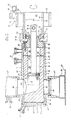
- Fig. 1 : einen Längsschnitt durch eine Vorrichtung,
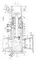
- Fig. 2 : einen Längsschnitt durch eine andere Vorrichtung und
- Fig. 3 : einen Längsschnitt durch eine weitere Vorrichtung.
- 1: a longitudinal section through a device,
- Fig. 2: a longitudinal section through another device and
- 3: a longitudinal section through a further device.
Eine Vorrichtung besteht im wesentlicehn aus einem Gehäuse (1), einem Drehschieber (2) und einem Kolbenkopf (3). Der Drehschieber (2) ist mit einem engen Paßsitz 4 in einem Innenraum (5) geführt, der innerhalb des Gehäuses (1) ausgebildet ist. In diesem Innenraum (5) ist der Drehschieber (2) sowohl um seine Längsachse drehbar als auch in axialer Richtung verschieblich gelagert. Die Lagerung erfolgt auf einer dem Gehäuse (1) zugewandten Außenfläche (6) des Drehschiebers (2), die eine ihr gegenüberliegende Innenfläche (7) des Gehäuses (1) gleitend beaufschlagt, die den Innenraum (5) begrenzt.A device consists essentially of a housing (1), a rotary valve (2) and a piston head (3). The rotary valve (2) is guided with a
Der Drehschieber (2) ist als ein Meßbehälter ausgebildet, in dessen Inneren ein Hohlraum (8) vorgesehen ist. Dieser Hohlraum (8) erstreckt sich in axialer Richtung des Drehschiebers (2) und ist annähernd zylindrisch ausgebildet. In diesem Hohlraum (8) gleitet in axialer Richtung der Kolbenkopf (3), an dem eine Kolbenstange (9) befestigt ist, die mit ihrem dem Kolbenkopf (3) gegenüberliegenden Ende (10) aus dem Drehschieber (2) herausragt. Dieser ist an seinem dem Ende (10) der Kolbenstange (9) benachbarten Ende (12) von einer Wandung (11) abgeschlossen, die von einer Öffnung (13) durchdrungen ist. In dieser Öffnung (13) wird die Kolbenstange (9) geführt. Diese hat einen runden oder quadratischen Querschnitt, so daß auch die Öffnung (13) einen entsprechenden Querschnitt aufweist.
Darüber hinaus ist am Ende (10) der Kolbenstange (9) eine Ankopplungsvorrichtung (15) vorgesehen, an der ein die Kolbenstange (9) bewegender nicht dargestellter Antrieb angekoppelt werden kann. Diese Ankopplungsvorrichtung (15) ist als eine Bohrung ausgebildet, die quer zur Längsrichtung der Kolbenstange (9) diese durchdringt.The rotary valve (2) is designed as a measuring container, in the interior of which a cavity (8) is provided. This cavity (8) extends in the axial direction of the rotary valve (2) and is approximately cylindrical. In this cavity (8) the piston head (3) slides in the axial direction, to which a piston rod (9) is attached, which protrudes with its end (10) opposite the piston head (3) from the rotary valve (2). This is closed at its end (10) of the piston rod (9) adjacent end (12) by a wall (11) which is penetrated by an opening (13). The piston rod (9) is guided in this opening (13). This has a round or square cross section, so that the opening (13) also has a corresponding cross section.
In addition, a coupling device (15) is provided at the end (10) of the piston rod (9), to which a drive (not shown) which moves the piston rod (9) can be coupled. This coupling device (15) is designed as a bore which penetrates the piston rod (9) transversely to the longitudinal direction thereof.
Am Ende (12) des Drehschiebers (2) ist in die Wandung (11) eine ringförmige Nut (16) eingelassen, deren einander sich gegenüberliegenden sich in radialer Richtung erstreckenden Wandungen als Gleitflächen (17, 18) ausgebildet sind. Auf diesen Gleitflächen (17, 18) gleitet eine Kupplung (19), die mit einem nicht dargestellten Antrieb verbunden ist, der in der Lage ist, den Drehschieber (2) in axialer Richtung zu verschieben.At the end (12) of the rotary valve (2), an annular groove (16) is let into the wall (11), the mutually opposite walls of which extend in the radial direction are designed as sliding surfaces (17, 18). A coupling (19) slides on these sliding surfaces (17, 18), which is connected to a drive, not shown, which is capable of displacing the rotary valve (2) in the axial direction.
Der Drehschieber (2) ragt mit seinem Ende (12) aus einem hinteren Teil (20) des Gehäuses (1) heraus. Auf diesem aus dem Gehäuse (1) herausragenden Ende (12) ist die Nut (16) vorgesehen. Von diesem Ende (12) verläuft die Außenfläche (6) in Richtung auf sein gegenüberliegendes vorderes Ende (21) konisch in der Weise, daß sich die Querschnitte vom hinteren Ende (12) in Richtung auf das vordere Ende (21) verjüngen. In entsprechender Weise ist auch die Innenfläche (7) des Innenraumes (5) konisch ausgebildet, so daß sie im Bereich ihres hinteren Teils (20) ihren größten Querschnitt besitzt.The end of the rotary slide (2) protrudes (12) from a rear part (20) of the housing (1). The groove (16) is provided on this end (12) protruding from the housing (1). From this end (12), the outer surface (6) tapers towards its opposite front end (21) in such a way that the cross sections taper from the rear end (12) towards the front end (21). Correspondingly, the inner surface (7) of the interior (5) is conical, so that it has its largest cross section in the area of its rear part (20).
Der Hohlraum (8) ist an seinem der Wandung (11) benachbarten Ende als eine Reinigungskammer (22) ausgebildet. Diese besitzt einen größeren Querschnitt als ein dem vorderen Teil (21) zugewandter Zylinderteil (23), dessen Querschnitt so bemessen ist, daß der in ihm gleitende Kolbenkopf (3) mit einer so engen Passung geführt wird, daß er in der Lage ist, je nach Bewegungsrichtung innerhalb des Zylinderteils (23) einen Unter- bzw. Überdruck zu erzeugen. Der Kolbenkopf (3) trägt an seinem der Kolbenstange (9) benachbarten Ende eine Kolbenmanschette (24), die mit ihrer Außenfläche (25) für einen druckdichten Abschluß des Kolbenkopfes (3) innerhalb des Hohlraumes (8) sorgt.The cavity (8) is designed as a cleaning chamber (22) at its end adjacent to the wall (11). This has a larger cross section than a front part (21) facing cylinder part (23), the cross section of which is dimensioned such that the piston head (3) sliding in it is guided with such a close fit that it is capable of depending to generate a negative or positive pressure within the cylinder part (23) according to the direction of movement. The piston head (3) carries at its end adjacent to the piston rod (9) a piston sleeve (24), which with its outer surface (25) ensures a pressure-tight seal of the piston head (3) within the cavity (8).
Zwischen der Reinigungskammer (22) und dem Zylinderteil (23) ist eine Übergangszone (26) vorgesehen, in der der Querschnitt des Zylinderteils (23) sich stetig erweitert auf den Querschnitt der Reinigungskammer (22). In der Reinigungskammer (22) sind Zutrittsöffnungen (27) für eine Reinigungsflüssigkeit vorgesehen, die über einen Reinigungsanschluß (28) zugeführt wird.A transition zone (26) is provided between the cleaning chamber (22) and the cylinder part (23), in which the cross section of the cylinder part (23) continually widens to the cross section of the cleaning chamber (22). Access openings (27) for a cleaning liquid are provided in the cleaning chamber (22) and are supplied via a cleaning connection (28).
Dieser Reinigungsanschluß (28) reicht durch das Gehäuse (1) hindurch in den Innenraum (5).This cleaning connection (28) extends through the housing (1) into the interior (5).
Ein weiterer Reinigungsanschluß (33) ist vorgesehen an einem dem vorderen Ende (21) benachbarten vorderen Ende (34) des Gehäuses (1). Dieser Reinigungsanschluß (33) fluchtet mit einer Zutrittsöffnung (35), die im Bereich des vorderen Endes (21) in den Innenraum (5) mündet. Darüber hinaus ist ein weiterer Reinigungsanschluß (36) im Bereich eines Einlaufs (37) vorgesehen, durch den ein abzufüllendes Produkt über eine Bohrung (38) in das Gehäuse (1) und von diesem über eine Öffnung (39) in den Zylinderteil (23) des Hohlraumes (8) eintritt. Der Einlauf (37) kann als eine Rohrleitung ausgebildet sein, die mit einem entsprechend ausgebildeten Flansch fest verbunden ist, der die Bohrung (38) umgibt und mit dem Gehäuse (1) fest verbunden ist.A further cleaning connection (33) is provided on a front end (34) of the housing (1) which is adjacent to the front end (21). This cleaning connection (33) is aligned with an access opening (35) which opens into the interior (5) in the region of the front end (21). In addition, a further cleaning connection (36) is provided in the area of an inlet (37) through which a product to be filled is passed through a bore (38) into the housing (1) and from there via an opening (39) into the cylinder part (23). of the cavity (8) occurs. The inlet (37) can be designed as a pipeline which is fixedly connected to a correspondingly designed flange which surrounds the bore (38) and is fixedly connected to the housing (1).
Das Gehäuse (1) ist an seinem vorderen Ende (34) mit einer Bohrung (41) versehen, deren Querschnitt kleiner als der des ihm benachbarten Innenraumes (5) ist. Diese Bohrung (41) ist von einer Kappe (42) verschlossen, die mit einem Bund in der Bohrung (41) geführt wird. An diesen Bund schließt sich in Richtung auf den Innenraum (5) ein Lagerzapfen (44) an, dessen Querschnitt dem Querschnitt des Zylinderteils (23) entspricht, in den der Lagerzapfen (44) passend hineinragt. Auf diesem Lagerzapfen (44) wird der Drehschieber (2) im Bereich seines vorderen Endes (21) geführt. Diese Kappe (42) wird auf ihrer dem Lagerzapfen (44) abgewandten Außenseite von einer Deckfläche begrenzt, die über den Bund hinausragt und die Bohrung (41) druckdicht verschließt.The housing (1) is provided at its front end (34) with a bore (41), the cross section of which is smaller than that of the interior (5) adjacent to it. This bore (41) is closed by a cap (42) which is guided with a collar in the bore (41). A bearing journal (44) adjoins this collar in the direction of the interior (5), the cross section of which corresponds to the cross section of the cylinder part (23) into which the bearing journal (44) projects. The rotary slide valve (2) is guided in the region of its front end (21) on this bearing journal (44). This cap (42) is delimited on its outside facing away from the bearing journal (44) by a cover surface which projects beyond the collar and closes the bore (41) in a pressure-tight manner.
Der Innenraum (5) besitzt eine Auslaßbohrung (46), die der Bohrung (38) um einen Drehwinkel von etwa 180° bezüglich des Gehäuses (1) gegenüberliegt. Diese Auslaßbohrung (46) fluchtet mit der Öffnung (39) des Drehschiebers (2) und damit mit der Bohrung (38). Sie mündet in ein Mundstück (47), das unmittelbar oberhalb einer abzufüllenden Verpackungseinheit, beispielsweise eines Bechers (48) angeordnet ist. Dieser Becher (48) wird mit Hilfe einer Fördereinrichtung (49), beispielsweise eines Förderbandes in Richtung auf das Mundstück (47) transportiert bzw. von diesem weggefördert.The interior (5) has an outlet bore (46) which is opposite the bore (38) by an angle of rotation of approximately 180 ° with respect to the housing (1). This outlet bore (46) is aligned with the opening (39) of the rotary valve (2) and thus with the bore (38). It opens into a mouthpiece (47), for example, immediately above a packaging unit to be filled a cup (48) is arranged. This cup (48) is transported with the aid of a conveyor device (49), for example a conveyor belt, in the direction of the mouthpiece (47) or is conveyed away therefrom.
Mit der Wandung (11) ist eine Anschlußhülse (70) über Schrauben (71) fest verbunden, die durch einen der Wandung (11) zugewandten Flansch (72) hindurch in Schraubenlöcher (73) hineinragen, die in der Wandung (11) vorgesehen sind. Mit Hilfe der Schrauben (71) wird der der Wandung (11) zugewandte Flansch (72) fest verschraubt.A connection sleeve (70) is firmly connected to the wall (11) by means of screws (71) which protrude through a flange (72) facing the wall (11) into screw holes (73) provided in the wall (11) . With the aid of the screws (71), the flange (72) facing the wall (11) is firmly screwed.
Die Anschlußhülse (70) erstreckt sich in eine vom vorderen Ende (21) abgewandte Richtung und ist als ein Rohrstück ausgebildet, mit dem ein Drehantrieb (75) für den Drehschieber (2) verbunden ist. Dieser Drehantrieb(75)kann beispielsweise als ein Ritzel (76) ausgebildet sein, das auf einer Oberfläche (74) der rohrförmigen Anschlußhülse (70) befestigt, beispielsweise aufgeschrumpft ist. Dieses Ritzel (76) hat eine relativ große Breite, die größer ist als die eines Antriebszahnrades (77), das mit dem Ritzel (76) im Eingriff ist. Dieses Antriebszahnrad (77) ist auf einer Antriebswelle (78) befestigt, die von einem Elektromotor (79) angetrieben wird. Die gegenüber dem Antriebszahnrad (77) vergleichsweise große Breite des Ritzels (76) gestattet eine Verschiebung der Anschlußhülse (70) in deren Längsrichtung, ohne daß deswegen das Antriebszahnrad (77) mit dem Ritzel (76) außer Eingriff gerät.The connecting sleeve (70) extends in a direction facing away from the front end (21) and is designed as a piece of pipe to which a rotary drive (75) for the rotary slide valve (2) is connected. This rotary drive (75) can be designed, for example, as a pinion (76) which is fastened, for example shrunk, onto a surface (74) of the tubular connecting sleeve (70). This pinion (76) has a relatively large width which is larger than that of a drive gear (77) which is in engagement with the pinion (76). This drive gear (77) is fastened to a drive shaft (78) which is driven by an electric motor (79). The comparatively large width of the pinion (76) compared to the drive gear (77) allows the connecting sleeve (70) to be displaced in its longitudinal direction without the drive gear (77) therefore becoming disengaged from the pinion (76).
Die Anschlußhülse (70) hat einen relativ großen Innendurchmesser (80). Ihm entspricht ein von einer Wandung (81) der Anschlußhülse (70) umspannter Innenraum (82), in den die Kolbenstange (9) mit ihrem Ende (10) hineinragt. Innerhalb des Innenraumes (82) kann ein die Kolbenstange bewegender nicht dargestellter Antrieb mit der Ankopplungsvorrichtung (15) in Eingriff gebracht werden.The connecting sleeve (70) has a relatively large inner diameter (80). One of a wall corresponds to it (81) of the connecting sleeve (70) spanned interior (82) into which the piston rod (9) protrudes with its end (10). A drive (not shown) which moves the piston rod can be brought into engagement with the coupling device (15) inside the interior (82).
Die Anschlußhülse (70) wird auf ihrer Oberfläche (74) von der Kupplung (19) mit geringem Spiel umschlossen. Mit Hilfe dieser Kupplung (19) kann sowohl der Drehschieber (2) als auch die mit ihr verbundene Anschlußhülse (70) in ihren Längsrichtungen bewegt werden.The connector sleeve (70) is enclosed on its surface (74) by the coupling (19) with little play. With the help of this coupling (19), both the rotary valve (2) and the connecting sleeve (70) connected to it can be moved in their longitudinal directions.
Aus einem nicht dargestellten Vorratsbehälter wird das abzufüllende Produkt, beispielsweise ein mit festen Bestandteilen durchsetztes Milchprodukt durch den Einlauf (37) in Richtung auf die Bohrung (38) und die Öffnung (39) gefördert, die während der Befüllung des Zylinderteils (23) mit der Bohrung (38) fluchtet. Zur Beschleunigung der Befüllung wird das Produkt dadurch angesaugt, daß der Kolbenkopf (3) in Richtung auf die Reinigungskammer (22) bewegt wird und im Zylinderteil (23) ein Unterdruck erzeugt wird. Die Bewegung des Kolbenkopfes kommt vor Erreichen der Reinigungskammer (22) zum Ende.From a storage container, not shown, the product to be filled, for example a milk product interspersed with solid components, is conveyed through the inlet (37) in the direction of the bore (38) and the opening (39), which during the filling of the cylinder part (23) with the Hole (38) is aligned. To accelerate the filling, the product is sucked in that the piston head (3) is moved in the direction of the cleaning chamber (22) and a negative pressure is generated in the cylinder part (23). The movement of the piston head comes to an end before it reaches the cleaning chamber (22).
Nunmehr wird der Elektromotor (79), bei dem es sich um einen Schrittschaltmotor handeln kann, eingeschaltet, der über das Antriebszahnrad (77) und das Ritzel (66) die Anschlußhülse (70) und damit den Drehschieber (2) um einen Winkel von 180° verdreht. Dabei gelangt die Öffnung (39) in den Bereich der Auslaßbohrung (46). Sobald die Öffnung (39) mit der Auslaßbohrung (46) fluchtet, wird der Kolbenkopf (3) in Richtung auf das vordere Ende (21) bewegt und dabei das im Zylinderteil (23) enthaltene Produkt durch die Auslaßbohrung (46) in Richtung auf den Becher (48) ausgestoßen.Now the electric motor (79), which can be a stepping motor, is switched on, which via the drive gear (77) and the pinion (66) connects the connecting sleeve (70) and thus the rotary valve (2) through an angle of 180 ° twisted. The opening (39) reaches the area of the outlet bore (46). As soon as the opening (39) is aligned with the outlet bore (46), the piston head (3) is moved towards the front end (21) and the product contained in the cylinder part (23) through the outlet bore (46) towards the Ejected cup (48).
Sobald der Kolbenkopf (3) seine vordere Position im Bereich des vorderen Endes (21) erreicht hat, wird der Drehschieber (2) um seine Mittelachse gedreht, bis neuerdings die Öffnung (39) mit der Bohrung (38) fluchtet. In dieser Stellung kann das Produkt in die Öffnung (39) eintreten. Zur Vergrößerung der Eintrittsgeschwindigkeit wird der Kolbenkopf (3) in Richtung auf die Reinigungskammer (22) bewegt, so daß in einem dem vorderen Ende (21) benachbarten Teil des Zylinderteils (23) neuerdings ein Unterdruck entsteht, der das Produkt in den Zylinderteil (23) ansaugt.As soon as the piston head (3) has reached its front position in the region of the front end (21), the rotary slide valve (2) is rotated about its central axis until the opening (39) is aligned with the bore (38). In this position, the product can enter the opening (39). In order to increase the entry speed, the piston head (3) is moved in the direction of the cleaning chamber (22), so that a vacuum is now created in a part of the cylinder part (23) which is adjacent to the front end (21) and which pushes the product into the cylinder part (23 ) sucks.
Zum Zwecke der Reinigung der Vorrichtung wird der Drehschieber (2) mit Hilfe der Kupplung (19) in Richtung auf sein hinteres Ende (12) aus dem Paßsitz (4) herausgezogen. Dabei genügt eine relativ kleine Versetzung des Drehschiebers (2). Um die Größe dieser Versetzung gleitet das Antriebszahnrad (77) durch die mit ihm im Eingriff befindlichen Zähne des Ritzels (76). Diese Versetzung reicht aus, um im Hinblick auf die konische Ausbildung sowohl der Innenfläche (7) als auch der Außenfläche (6) den Sitz des Drehschiebers (2) innerhalb des Innenraumes (5) so weitgehend zu lockern, daß eine durch die Reinigungsanschlüsse (28) und (33) eintretende Reinigungsflüssigkeit sich zwischen die Außenfläche (6) einerseits und die Innenfläche (7) andererseits durchdrücken kann. Darüber hinaus tritt durch den Reinigungsanschluß (33) die Reinigungsflüssigkeit in den Bereich des vorderen Endes (21) des Drehschiebers (2) so daß auch diese in dem gewünschten Umfange gereinigt wird. Dabei tritt die Reinigungsflüssigkeit durch den Reinigungsanschluß (33) sowohl über den Bund (44) in den Hohlraum (8) als auch über die Außenfläche (6) in die Öffnung (39) ein. Schließlich gelangt Reinigungsflüssigkeit durch den Reinigunsanschluß (36) in den Einlauf (37) und damit in den Hohlraum (8). Gleichzeitig wird der Kolbenkopf (3) bis in die Reinigungskammer (22) zurückgezogen, so daß er dort allseits von der durch die Zutrittsöffnung (27) zutretenden Reinigungsflüssigkeit umspült wird. Dabei ist der Querschnitt der Reinigungskammer (22) so gewählt, daß der Kolbenkopf (3) an ihren Innenwandungen nicht anliegt, wenn er in sie hineingezogen ist. Auf diese Weise wird der Kolbenkopf (3) allseitig von Reinigungsmittel umspült, das die Reinigungskammer (22) über eine Auslaßöffnung (50) verläßt, die im Drehschieber (2) vorgesehen ist und mit einer Ablaßöffnung (51) fluchtet, die im Gehäuse (1) vorgesehen ist und aus der Reinigungsflüssigkeit in Richtung auf einen nicht dargestellten Auffangbehalter austritt.For the purpose of cleaning the device, the rotary valve (2) is pulled out of the snug fit (4) in the direction of its rear end (12) with the aid of the coupling (19). A relatively small displacement of the rotary valve (2) is sufficient. The drive gear (77) slides by the size of this displacement through the teeth of the pinion (76) which are in engagement with it. This displacement is sufficient to loosen the seat of the rotary slide valve (2) within the interior (5) to such an extent that, due to the conical shape of both the inner surface (7) and the outer surface (6), that a through the cleaning connections (28 ) and (33) entering cleaning liquid between the outer surface (6) on the one hand and the inner surface (7) on the other. In addition, the cleaning liquid passes through the cleaning connection (33) into the region of the front end (21) of the rotary slide valve (2), so that it is also cleaned to the desired extent. The cleaning liquid enters through the cleaning connection (33) both via the collar (44) into the cavity (8) and via the outer surface (6) into the opening (39). Finally, cleaning liquid gets through the cleaning connection (36) into the Inlet (37) and thus into the cavity (8). At the same time, the piston head (3) is pulled back into the cleaning chamber (22), so that it is washed around on all sides by the cleaning liquid that enters through the access opening (27). The cross section of the cleaning chamber (22) is selected so that the piston head (3) does not rest on its inner walls when it is drawn into it. In this way, the piston head (3) is flushed on all sides with cleaning agent, which leaves the cleaning chamber (22) via an outlet opening (50) which is provided in the rotary valve (2) and is aligned with a drain opening (51) which is in the housing (1 ) is provided and emerges from the cleaning liquid in the direction of a collecting container, not shown.
Nachdem alle mit dem Produkt in Kontakt gewesenen Teile mit Reinigungsflüssigkeit ausgiebig umspült worden sind, wird der Reinigungsvorgang beendet. Zu diesem Zwecke wird der Zulauf von Reinigungsflüssigkeit zu den Reinigungsanschlüssen (28, 33, 36) unterbrochen und der Drehschieber (2) mit Hilfe der Kupplung (19) in axialer Richtung auf das vordere Ende (21) bewegt, so daß der enge Paßsitz (4) wieder hergestellt wird. In dieser Lage kann neuerdings die Befüllung der Becher (48) wieder aufgenommen werden, die auf der Fördereinrichtung (49) herantransportiert werden.After all parts in contact with the product have been thoroughly rinsed with cleaning liquid, the cleaning process is ended. For this purpose, the supply of cleaning fluid to the cleaning connections (28, 33, 36) is interrupted and the rotary valve (2) is moved in the axial direction onto the front end (21) by means of the coupling (19), so that the tight fit ( 4) is restored. In this position, the filling of the cups (48) can be resumed, which are transported up to the conveyor (49).
Es ist auch möglich, über die Anschlußhülse (70) unmittelbar die für das Verschieben des Drehschiebers (2) notwendigen Kräfte in diesen einzuleiten. Zu diesem Zwecke kann auf die Kupplung (19) verzichtet werden. Vielmehr wird die Anschlußhülse (70) über ein Zwischenstück (83) durch die Schrauben (71) unmittelbar mit dem Drehschieber (2) verbunden. Das Zwischenstück (83) dient lediglich dazu, eine Gleitbuchse (84) aufzunehmen, in der die Öffnung (13) zur Lagerung der Kolbenstange (9) vorgesehen ist.It is also possible, via the connecting sleeve (70), to introduce the forces necessary for displacing the rotary slide valve (2) directly into the latter. For this purpose, the coupling (19) can be omitted. Rather, the connecting sleeve (70) is connected directly to the rotary valve (2) via an intermediate piece (83) by means of the screws (71). The spacer (83) only serves to receive a sliding bush (84) in which the opening (13) is provided for mounting the piston rod (9).
Ein Antrieb (85) zur Verschiebung des Drehschiebers (2) in dessen Längsrichtung ist auf der Oberfläche (74) außer dem in Figur 2 nicht dargestellten Drehantrieb (75) befestigt. Dieser Verschiebeantrieb (85) besteht im wesentlichen aus einem Ring (86), der auf der Oberfläche (74) in Längsrichtung der Anschlußhülse (70) unverschieblich befestigt, beispielsweise aufgeschrumpft ist. Dieser Ring (86) ist gegenüber einem Mitnehmer (87) drehbar gelagert, der lediglich Bewegungen in Längsrichtung der Anschlußhülse (70), nicht jedoch Drehbewegungen durchführen kann. Die drehbare Lagerung des Mitnehmers (87) gegenüber dem Ring (86) kann beispielsweise mit Hilfe eines Rillenkugellagers (88) erfolgen, das die zum Verschieben des Drehschiebers (2) notwendigen Kräfte vom Mitnehmer (87) auf den Ring (86) überträgt. Es ist jedoch auch möglich, statt eines Rillenkugellagers (88) ein Gleitlager zwischen dem Mitnehmer (87) und dem Ring (86) anzuordnen.A drive (85) for displacing the rotary valve (2) in its longitudinal direction is attached to the surface (74) in addition to the rotary drive (75), which is not shown in FIG. 2. This displacement drive (85) consists essentially of a ring (86) which is fixed immovably on the surface (74) in the longitudinal direction of the connecting sleeve (70), for example shrunk on. This ring (86) is rotatably supported relative to a driver (87) which can only perform movements in the longitudinal direction of the connecting sleeve (70), but not rotary movements. The rotatable mounting of the driver (87) relative to the ring (86) can take place, for example, with the aid of a deep groove ball bearing (88) which transfers the forces required to move the rotary valve (2) from the driver (87) to the ring (86). However, it is also possible to arrange a plain bearing between the driver (87) and the ring (86) instead of a deep groove ball bearing (88).
Der Mitnehmer kann beispielsweise als eine sich in Längsrichtung der Anschlußhülse parallel zu deren Oberfläche (74) erstreckende Verschiebehülse (89) ausgebildet sein, die an ihrem dem Ring (86) zugewandten Ende mit einer den Ring (86) aufnehmenden Nut (90) versehen ist, in der der Ring (86) drehbar gelagert ist. Auf der Verschiebehülse (89) kann beispielsweise eine sich in Längsrichtung der Anschlußhülse (70) erstreckende Zahnstange (91) befestigt sein, in deren Zähne ein von einem nicht dargestellten Antriebsmotor angetriebenes Ritzel (92) eingreift. Je nach der gewünschten Verschieberichtung des Drehschiebers (2) wird das Ritzel (92) in die eine oder andere Richtung bewegt. Es nimmt die Zahnstange (91) und damit den Ring (86) mit, über den der Drehschieber (2) entweder in die Reinigungsposition gezogen oder aus dieser wieder in die Befüllposition zurückgeschoben wird.The driver can, for example, be designed as a sliding sleeve (89) extending in the longitudinal direction of the connecting sleeve parallel to its surface (74), which is provided at its end facing the ring (86) with a groove (90) receiving the ring (86) , in which the ring (86) is rotatably mounted. A rack (91) extending in the longitudinal direction of the connecting sleeve (70), for example, can be fastened to the sliding sleeve (89) and a toothed pinion (92) driven by a drive motor (not shown) engages in the teeth thereof. Depending on the desired direction of displacement of the rotary valve (2), the pinion (92) moved in one direction or the other. It takes the rack (91) and thus the ring (86) with it, via which the rotary slide (2) is either pulled into the cleaning position or pushed out of this back into the filling position.
Es ist auch möglich, das Zwischenstück (83) unmittelbar mit der Anschlußhülse (70) zu verbinden, so daß diese unmittelbar über die Schrauben (71) mit dem Drehschieber (2) verbunden ist. Zu diesem Zwecke ist die Anschlußhülse (70) an ihrem dem Drehschieber (2) zugewandten Ende mit einem Flansch (93) versehen, durch den die Schrauben (71) hindurch in den Drehschieber (2) hineinragen. Dieser Flansch (93) liegt unmittelbar an einer am Drehschieber (2) vorgesehenen radial verlaufenden Auflagefläche (94) an. Außerdem dient der Flansch (93) zur Aufnahme der Gleitbuchse (84), in der die Kolbenstange (9) gelagert ist. Durch die unmittelbare Verbindung der Anschlußhülse (70) mit dem Drehschieber (2) wird eine kurze, gedrungene Konstruktion angestrebt, die eine Anordnung sowohl des Drehantriebes (75) als auch des Verschiebeantriebes (85) an einer Stelle gestattet, die möglichst nahe am Drehschieber (2) liegt. In jedem Falle ist jedoch die Verbindung der Anschlußhülse (70) mit dem Drehschieber (2) so gewählt, daß die zur Verdrehung des Drehschiebers (2) notwendigen Drehmomente an einer Stelle in den Drehschieber (2) eingeleitet werden, die möglichst weit am äußeren Umfange des Drehschiebers (2) liegt.It is also possible to connect the intermediate piece (83) directly to the connecting sleeve (70) so that it is connected directly to the rotary slide valve (2) via the screws (71). For this purpose, the connecting sleeve (70) is provided at its end facing the rotary valve (2) with a flange (93) through which the screws (71) protrude into the rotary valve (2). This flange (93) bears directly on a radially extending support surface (94) provided on the rotary slide valve (2). In addition, the flange (93) serves to receive the slide bush (84) in which the piston rod (9) is mounted. The direct connection of the connecting sleeve (70) to the rotary valve (2) is aimed at a short, compact construction which allows the rotary actuator (75) as well as the sliding actuator (85) to be arranged at a point as close as possible to the rotary valve ( 2) lies. In any case, however, the connection of the connecting sleeve (70) with the rotary valve (2) is selected so that the torques necessary for rotating the rotary valve (2) are introduced into the rotary valve (2) at one point, as far as possible on the outer circumference of the rotary valve (2).
Die Kolbenstange (9) kann jeden beliebigen Querschnitt aufweisen, beispielsweise einen kreisförmigen oder eckigen Querschnitt. Die Wahl eines kreisförmigen Querschnittes bietet sich an, da er eine billige und einfache Gestaltung der Gleitbuchse (84) zuläßt. Die Lagerung des Drehschiebers (2) erfolgt sowohl zum Zwecke der Ausführung von Drehbewegungen als auch von axialen Bewegungen auf einer Lagerbuchse (52).The piston rod (9) can have any cross section, for example a circular or angular cross section. The choice of a circular cross section is advisable since it allows a cheap and simple design of the slide bush (84). Warehousing of the rotary valve (2) is carried out on a bearing bush (52) both for the purpose of executing rotary movements and of axial movements.
Claims (23)
Priority Applications (1)
| Application Number | Priority Date | Filing Date | Title |
|---|---|---|---|
| AT87105596T ATE91985T1 (en) | 1986-04-19 | 1987-04-15 | DEVICE FOR MEASURING A FLOWABLE PRODUCT. |
Applications Claiming Priority (2)
| Application Number | Priority Date | Filing Date | Title |
|---|---|---|---|
| DE19863613266 DE3613266A1 (en) | 1986-04-19 | 1986-04-19 | DEVICE FOR MEASURING A FLOWABLE PRODUCT |
| DE3613266 | 1986-04-19 |
Publications (3)
| Publication Number | Publication Date |
|---|---|
| EP0242786A2 true EP0242786A2 (en) | 1987-10-28 |
| EP0242786A3 EP0242786A3 (en) | 1988-09-07 |
| EP0242786B1 EP0242786B1 (en) | 1993-07-28 |
Family
ID=6299064
Family Applications (1)
| Application Number | Title | Priority Date | Filing Date |
|---|---|---|---|
| EP87105596A Expired - Lifetime EP0242786B1 (en) | 1986-04-19 | 1987-04-15 | Device for measuring a fluid product |
Country Status (6)
| Country | Link |
|---|---|
| US (1) | US4867351A (en) |
| EP (1) | EP0242786B1 (en) |
| AT (1) | ATE91985T1 (en) |
| CA (1) | CA1279045C (en) |
| DE (2) | DE3613266A1 (en) |
| DK (1) | DK189287A (en) |
Cited By (1)
| Publication number | Priority date | Publication date | Assignee | Title |
|---|---|---|---|---|
| WO2011085709A1 (en) | 2010-01-15 | 2011-07-21 | Sig Technology Ag | Method and device for filling products |
Families Citing this family (3)
| Publication number | Priority date | Publication date | Assignee | Title |
|---|---|---|---|---|
| WO2001083299A1 (en) * | 2000-05-04 | 2001-11-08 | Sig Pack Sapal S.A. | Machine for metering and filling liquid or pasty products |
| US8534507B2 (en) * | 2011-05-11 | 2013-09-17 | Mike Gronholm | Granule dispensers |
| US10130110B2 (en) * | 2014-04-25 | 2018-11-20 | Bühler AG | Depositing machine having a plug-in connection |
Citations (2)
| Publication number | Priority date | Publication date | Assignee | Title |
|---|---|---|---|---|
| GB2156911A (en) * | 1984-04-04 | 1985-10-16 | Benz & Hilgers Gmbh | Apparatus for dispensing measured quantities of a fluid or semi-solid substance |
| EP0185958A2 (en) * | 1984-11-29 | 1986-07-02 | Lieder Maschinenbau GmbH & Co. KG | Method and apparatus for metering a free-flowing product |
Family Cites Families (7)
| Publication number | Priority date | Publication date | Assignee | Title |
|---|---|---|---|---|
| US845572A (en) * | 1906-05-31 | 1907-02-26 | Scott Peck | Measuring device. |
| GB521504A (en) * | 1938-11-16 | 1940-05-23 | Bror Anders Emil Johnson | Improved apparatus for and method of distributing portions of paste or other semi-liquid material |
| CH351135A (en) * | 1958-12-22 | 1960-12-31 | Kustner Freres Cie Sa | Moulder-dosing machine for pasty material |
| US3140018A (en) * | 1962-10-15 | 1964-07-07 | Theodore A Miller | Powder dispensing unit |
| US3335724A (en) * | 1964-07-24 | 1967-08-15 | Erich M Gienapp | Remote control, repeating, variable stroke hypodermic syringe device |
| US3844002A (en) * | 1973-03-16 | 1974-10-29 | Gen Tire & Rubber Co | Gripper assembly for jacking mechanisms |
| US4084729A (en) * | 1975-08-28 | 1978-04-18 | Maryland Cup Corporation | Dispensing valve |
-
1986
- 1986-04-19 DE DE19863613266 patent/DE3613266A1/en not_active Withdrawn
-
1987
- 1987-04-13 US US07/038,395 patent/US4867351A/en not_active Expired - Fee Related
- 1987-04-13 DK DK189287A patent/DK189287A/en not_active Application Discontinuation
- 1987-04-15 AT AT87105596T patent/ATE91985T1/en not_active IP Right Cessation
- 1987-04-15 EP EP87105596A patent/EP0242786B1/en not_active Expired - Lifetime
- 1987-04-15 DE DE8787105596T patent/DE3786691D1/en not_active Expired - Fee Related
- 1987-04-16 CA CA000534944A patent/CA1279045C/en not_active Expired - Fee Related
Patent Citations (2)
| Publication number | Priority date | Publication date | Assignee | Title |
|---|---|---|---|---|
| GB2156911A (en) * | 1984-04-04 | 1985-10-16 | Benz & Hilgers Gmbh | Apparatus for dispensing measured quantities of a fluid or semi-solid substance |
| EP0185958A2 (en) * | 1984-11-29 | 1986-07-02 | Lieder Maschinenbau GmbH & Co. KG | Method and apparatus for metering a free-flowing product |
Cited By (3)
| Publication number | Priority date | Publication date | Assignee | Title |
|---|---|---|---|---|
| WO2011085709A1 (en) | 2010-01-15 | 2011-07-21 | Sig Technology Ag | Method and device for filling products |
| CN102791583A (en) * | 2010-01-15 | 2012-11-21 | Sig技术股份公司 | Method and device for filling products |
| CN102791583B (en) * | 2010-01-15 | 2014-09-03 | Sig技术股份公司 | Method and device for filling products |
Also Published As
| Publication number | Publication date |
|---|---|
| DE3613266A1 (en) | 1987-10-22 |
| US4867351A (en) | 1989-09-19 |
| DK189287A (en) | 1987-10-20 |
| DE3786691D1 (en) | 1993-09-02 |
| EP0242786B1 (en) | 1993-07-28 |
| EP0242786A3 (en) | 1988-09-07 |
| DK189287D0 (en) | 1987-04-13 |
| CA1279045C (en) | 1991-01-15 |
| ATE91985T1 (en) | 1993-08-15 |
Similar Documents
| Publication | Publication Date | Title |
|---|---|---|
| EP0185958B1 (en) | Method and apparatus for metering a free-flowing product | |
| DE3938353A1 (en) | Spindle drive for selective linear and rotary movements - affords mixt. of translation and rotation when heads are driven with unequal speeds in opposite directions | |
| EP2266409A1 (en) | Device for filling casings | |
| DE1944276U (en) | FLEXIBLE CONVEYOR DEVICE. | |
| DE2006930A1 (en) | Machine for the preparation of infusion beverages, in particular espresso coffee | |
| EP1361185A2 (en) | Dispenser for flowable material | |
| EP1101538A2 (en) | Electrically driven dispensing apparatus for cartridges | |
| EP0242786A2 (en) | Device for measuring a fluid product | |
| DE19641972C2 (en) | Device for stirring, mixing, crushing or the like | |
| DE4206966A1 (en) | Drive for package making extruder | |
| DE1629717A1 (en) | Mixer drive | |
| DE4009231C2 (en) | ||
| DE10244967B4 (en) | Device for plasticizing and injecting plastic | |
| DE102007027212A1 (en) | Electric injection molding device for plastic injection molding presses | |
| DE2626196A1 (en) | DEVICE FOR CONVEYING SCHUETTGUETERN WITH A ROTATING MOUNTED AUGER | |
| DE3241108C2 (en) | ||
| EP0886127B1 (en) | Apparatus for metering a viscous product | |
| DE10137073A1 (en) | Injection unit for an injection molding machine has a flow channel to the nozzle through a mixing and metering unit around central piston end of screw | |
| DE2201316A1 (en) | Peristaltic dosing pump | |
| DE600202C (en) | Device for limiting the stroke of plungers of dental injection syringes | |
| WO2007036243A1 (en) | Spindle drive for an injection molding machine with a lubricating device | |
| WO2008106805A1 (en) | Administration appliance with occlusion identification | |
| EP0484705A1 (en) | Device for filling sausages | |
| DE19943709A1 (en) | Precision electric injection unit | |
| DE3221222A1 (en) | Sampling device for drawing samples from a liquid |
Legal Events
| Date | Code | Title | Description |
|---|---|---|---|
| PUAI | Public reference made under article 153(3) epc to a published international application that has entered the european phase |
Free format text: ORIGINAL CODE: 0009012 |
|
| AK | Designated contracting states |
Kind code of ref document: A2 Designated state(s): AT BE CH DE ES FR GB GR IT LI LU NL SE |
|
| PUAL | Search report despatched |
Free format text: ORIGINAL CODE: 0009013 |
|
| AK | Designated contracting states |
Kind code of ref document: A3 Designated state(s): AT BE CH DE ES FR GB GR IT LI LU NL SE |
|
| 17P | Request for examination filed |
Effective date: 19890307 |
|
| 17Q | First examination report despatched |
Effective date: 19900717 |
|
| GRAA | (expected) grant |
Free format text: ORIGINAL CODE: 0009210 |
|
| AK | Designated contracting states |
Kind code of ref document: B1 Designated state(s): AT BE CH DE ES FR GB GR IT LI LU NL SE |
|
| PG25 | Lapsed in a contracting state [announced via postgrant information from national office to epo] |
Ref country code: IT Free format text: LAPSE BECAUSE OF FAILURE TO SUBMIT A TRANSLATION OF THE DESCRIPTION OR TO PAY THE FEE WITHIN THE PRE;WARNING: LAPSES OF ITALIAN PATENTS WITH EFFECTIVE DATE BEFORE 2007 MAY HAVE OCCURRED AT ANY TIME BEFORE 2007. THE CORRECT EFFECTIVE DATE MAY BE DIFFERENT FROM THE ONE RECORDED.SCRIBED TIME-LIMIT Effective date: 19930728 Ref country code: FR Effective date: 19930728 Ref country code: GR Free format text: LAPSE BECAUSE OF FAILURE TO SUBMIT A TRANSLATION OF THE DESCRIPTION OR TO PAY THE FEE WITHIN THE PRESCRIBED TIME-LIMIT Effective date: 19930728 Ref country code: NL Effective date: 19930728 Ref country code: SE Effective date: 19930728 Ref country code: GB Effective date: 19930728 Ref country code: BE Effective date: 19930728 |
|
| REF | Corresponds to: |
Ref document number: 91985 Country of ref document: AT Date of ref document: 19930815 Kind code of ref document: T |
|
| REF | Corresponds to: |
Ref document number: 3786691 Country of ref document: DE Date of ref document: 19930902 |
|
| PG25 | Lapsed in a contracting state [announced via postgrant information from national office to epo] |
Ref country code: ES Free format text: LAPSE BECAUSE OF FAILURE TO SUBMIT A TRANSLATION OF THE DESCRIPTION OR TO PAY THE FEE WITHIN THE PRESCRIBED TIME-LIMIT Effective date: 19931108 |
|
| EN | Fr: translation not filed | ||
| NLV1 | Nl: lapsed or annulled due to failure to fulfill the requirements of art. 29p and 29m of the patents act | ||
| GBV | Gb: ep patent (uk) treated as always having been void in accordance with gb section 77(7)/1977 [no translation filed] |
Effective date: 19930728 |
|
| PG25 | Lapsed in a contracting state [announced via postgrant information from national office to epo] |
Ref country code: AT Effective date: 19940415 |
|
| PG25 | Lapsed in a contracting state [announced via postgrant information from national office to epo] |
Ref country code: LU Free format text: LAPSE BECAUSE OF NON-PAYMENT OF DUE FEES Effective date: 19940430 Ref country code: LI Effective date: 19940430 Ref country code: CH Effective date: 19940430 |
|
| PLBE | No opposition filed within time limit |
Free format text: ORIGINAL CODE: 0009261 |
|
| STAA | Information on the status of an ep patent application or granted ep patent |
Free format text: STATUS: NO OPPOSITION FILED WITHIN TIME LIMIT |
|
| 26N | No opposition filed | ||
| REG | Reference to a national code |
Ref country code: CH Ref legal event code: PL |
|
| PGFP | Annual fee paid to national office [announced via postgrant information from national office to epo] |
Ref country code: DE Payment date: 20000629 Year of fee payment: 14 |
|
| PG25 | Lapsed in a contracting state [announced via postgrant information from national office to epo] |
Ref country code: DE Free format text: LAPSE BECAUSE OF NON-PAYMENT OF DUE FEES Effective date: 20020201 |