EP0484705A1 - Device for filling sausages - Google Patents
Device for filling sausages Download PDFInfo
- Publication number
- EP0484705A1 EP0484705A1 EP91117608A EP91117608A EP0484705A1 EP 0484705 A1 EP0484705 A1 EP 0484705A1 EP 91117608 A EP91117608 A EP 91117608A EP 91117608 A EP91117608 A EP 91117608A EP 0484705 A1 EP0484705 A1 EP 0484705A1
- Authority
- EP
- European Patent Office
- Prior art keywords
- filling
- filling cylinder
- piston
- cylinder
- mass
- Prior art date
- Legal status (The legal status is an assumption and is not a legal conclusion. Google has not performed a legal analysis and makes no representation as to the accuracy of the status listed.)
- Withdrawn
Links
Images


Classifications
-
- A—HUMAN NECESSITIES
- A22—BUTCHERING; MEAT TREATMENT; PROCESSING POULTRY OR FISH
- A22C—PROCESSING MEAT, POULTRY, OR FISH
- A22C11/00—Sausage making ; Apparatus for handling or conveying sausage products during manufacture
- A22C11/02—Sausage filling or stuffing machines
- A22C11/08—Sausage filling or stuffing machines with pressing-worm or other rotary-mounted pressing-members
Definitions
- the filling cylinder can be arranged vertically with the filling nozzle on top or horizontally.
- the second end of the filling cylinder can be closed by a cover on which the filling nozzle is firmly attached.
- the filling cylinders are loaded with the piston in the end position.
- the lid is removed from the second end and the meat is filled through the second end into the filling cylinder, which is carried out either manually or with the aid of a filling device.
- the loss times for filling are considerable, and the known device can therefore only be operated with large interruptions.
- the throughput is due to this discontinuous operation and the filling capacity is very low, so that such a device is not suitable for large filling capacities.
- a filling system For large filling capacities, a filling system has been developed that works with a large number of filling cylinders.
- a separate loading station at which a filling device is provided, vacuumed sausage meat is pressed into the filling cylinder which is open at both ends and which is arranged horizontally.
- the cylinder which is open on both ends and filled with sausage meat, is transported after filling with transport devices to a filling station, in which the sausage meat is pressed from the filling cylinder into a filler neck by a piston.
- this known system there is a certain loss of time due to the cylinder change at the filling station, but this loss of time is partly compensated for by the previous filling at the loading station due to the assembly line operation.
- this known system is limited by the consistency of the meat. Due to the open cylinders on the front sides, the sausage meat must not start to flow due to the influence of gravity. When changing the filling cylinder, the meat surfaces must be brought against each other air-free and flat, because otherwise undesirable air pockets in the filled sausage are unavoidable.
- a filling device which also works with horizontal filling cylinders.
- the filling cylinders are transported back and forth between a loading station and a filling station.
- the distance between the loading station and the filling station is smaller, which means that the transport times can be shortened. This is achieved by means of an automatic two-cylinder change system.
- Another advantage of this device is that it works more hygienically than the system described above, since the filled cylinders are not transported unprotected.
- this device which is also constructed in the manner of a system, requires a comparatively large amount of space.
- this known device also has the same procedural restrictions as the system described above.
- the sausage meat surfaces must be brought flat and flat against each other during the filling cylinder change.
- changing the grade and cleaning are also very time-consuming.
- not insignificant, non-fillable residual quantities arise for the same reason as in the system described above.
- the object of the invention is to improve a device of the type mentioned in such a way that the effort and the manufacturing costs and the required space are reduced, the loss times are reduced and the previously mentioned procedural disadvantages of the prior art can be avoided.
- the device according to the invention should be suitable for use in smaller factories, easy to clean, and flexible in terms of type change and placement in the production area and achieve a good filling result largely independent of the roast consistency, that is to say even with flowing roasts, without any noteworthy, non-fillable residual quantities attack.
- the conveying device should preferably connect the filling device to the first end of the filling cylinder such that the mass from the filling device past the piston in the end position into the filling cylinder is promoted.
- This embodiment is particularly expedient because the first end at which the piston is guided into the filling cylinder is also used to fill the filling cylinder.
- the filling device the conveying device, the filling cylinder and the filling nozzle should be arranged together on a machine frame.
- the conveying device has a feed screw which is directed towards the filling cylinder and is arranged such that it can rotate.
- a screw conveyor is suitable for a particularly gentle conveying of the mass from the filling device to the filling cylinder.
- the feed screw can be arranged at an angle to the axis of the filling cylinder. This arrangement is particularly advantageous if the feed through the first end of the filling cylinder takes place from the rear, since the feed screw extends essentially into the rear space of the device, which is required anyway for the piston and its drive.
- the feed screw can be substantially aligned with the filling cylinder and can contain a cavity which is at least open towards the filling cylinder and within which the piston is movably arranged.
- This embodiment is particularly advantageous in that it strives for compactness with the procedural advantage of a flow of the mass that is as straight as possible, i.e. with minimized deflections and thus the lowest mechanical loads on the product.
- the feed screw and the piston are expediently arranged concentrically to one another.
- a cone attached to the first end of the filling cylinder, the inside diameter of which widens at least to the outside diameter of the feeding screw, and the piston in its end position can be provided between the filling cylinder and the feed screw outside of the filling cylinder at a distance from this.
- the piston In its end position, the piston is preferably essentially completely retracted into the cavity of the screw conveyor. With the help of the cone, an annular opening is created surrounding the piston, through which the mass released by the screw conveyor can enter the filling cylinder.
- the conveying device has an outlet opening which is closed by a closure member when the piston moves from its end position into the filling cylinder.
- a sleeve which is arranged coaxially to the filling cylinder and can be moved in its longitudinal direction and through which the piston can be moved can be provided as the closure member.
- the piston can alternatively be provided with an elongated cylindrical body, the length of which is dimensioned such that it acts as a closure member when the piston is in its end position in the filling cylinder is moved into it.
- the filling of the filling cylinder with mass is particularly easy if it is put under negative pressure in the meantime.
- the filling device preferably has a storage funnel which can be closed by a cover and in which a negative pressure is generated after the cover is closed in order to vent the mass.
- the filler neck can be closed by an outlet slide.
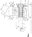
- a first embodiment of a filling device is shown schematically in cross section. With the help of the filling device shown, sausage and meat masses and, in particular, smear-sensitive sausage meat should be filled.
- the filling device contains a filling cylinder 1, which is arranged horizontally in the embodiment shown.
- the filling cylinder 1 is open to its two end faces. 1, a cone 2a is attached, which tapers the inner cross section of the filling cylinder 1 to a smaller cross section and on which a filler neck is arranged Section of the filling cylinder 1 tapers to a smaller cross section and on which a filler neck is arranged.
- the filler neck can be closed with an outlet slide 3.
- a piston 4 On the side of the filling cylinder 1 opposite the filling nozzle 2, a piston 4 is arranged, which can be moved into the latter by a hydraulic drive 5 through the open front side of the filling cylinder 1 opposite the filling nozzle 2, as shown in FIG. 1.
- a hydraulic drive 5 Through the open front side of the filling cylinder 1 opposite the filling nozzle 2, as shown in FIG. 1.
- the piston 4 In Fig. 1 the piston 4 is shown in its end position outside the filling cylinder 1.
- a cylindrical body 4a is formed on the piston 4 and has the same outer diameter as the piston 4.
- a feed screw 6 is provided which is rotatably mounted on bearings 20 within a screw housing 6a.
- the feed screw 6 has a cylindrical hollow body which is open towards its two end faces.
- the piston 4 is arranged inside the cavity 6b of the feed screw 6 thus formed, as can be seen in FIG. 1.
- the piston 4 can be moved out of the hollow feed screw 6 into the filling cylinder 1 by means of the hydraulic drive 5. Therefore, the diameter of the cavity 6b in the feed screw 6 must not be smaller than the outer diameter of the piston 4 and the cylindrical body 4a.
- the filling cylinder 1, the filling nozzle 2, the piston 4 with its cylindrical piston are located 4 with the cylindrical body 4a are arranged concentrically to each other.
- the outside diameter of the piston 4 essentially corresponds to the inside diameter of the filling cylinder 1. Since the outside diameter of the feed screw 6 and thus the inside diameter of the screw housing 6a is substantially larger than the inside diameter of the filling cylinder 1, the filling cylinder 1 is attached to the screw housing 6a via a cone 18, to create a transition from the smaller inner diameter of the filling cylinder 1 to the larger inner diameter of the screw housing 6a.
- An annular opening 18a is formed at the transition between the cone 18 and the screw housing 6a between the latter and the feed screw 6. This opening 18a serves as an outlet opening for the screw housing 6a or inlet opening for the filling cylinder 1.
- a motor 7 is provided for driving the feed screw 6, the rotor shaft of which is coupled to the feed screw 6 via a gear transmission 7a.
- the screw housing 6a opens to a storage hopper 8 sitting thereon, which can be closed by a cover 9 which is hinged to the upper part of the storage hopper 8 via a hinge 10.
- a corresponding drive 11 is provided for opening and closing the cover 9.
- the storage hopper 8 is filled from a sausage car 12, which is shown in FIG. 1 in the upturned position with the lid 9 open.
- the sausage meat can also be introduced into the storage hopper 8 via an inlet valve 13.
- a vacuum pump 14 is connected to the interior of the storage funnel 8 via a vacuum valve 15.
- An aeration valve 16 is also provided on the storage hopper 8. of the supply funnel 8 connected.
- An aeration valve 16 is also provided on the storage hopper 8.
- a vent valve 17 is provided on the filling cylinder 1, namely at its end adjacent to the cone 2a.
- the filling cylinder 1, the filler neck 2, the cone 18, the screw housing 6a and the funnel 8 essentially form a structural unit which is mounted on a machine frame 21. Accordingly, the filling cylinder 1, the filling nozzle 2, the piston 4, the feed screw 6 and the funnel 8 are arranged in a fixed manner relative to one another, although the piston 4 - as described above - can be reciprocally moved in the longitudinal direction of the filling cylinder 2.
- the storage hopper 8 can now be filled with the sausage meat 22 to be filled in that it is sucked in through the inlet valve 13 due to the negative pressure prevailing in the interior of the storage hopper 8.
- the filling can also take place from a container or a sausage car 12, as indicated in FIG. 1.
- the negative pressure in the storage hopper 8 is eliminated by the vacuum valve 15 being closed and the ventilation valve 16 is opened.
- the cover 9 is swung open on the cover hinge 10 by means of the drive 11.
- the meat 22 is now poured from the overturned meat car 12 into the storage hopper 8.
- the lid 9 is closed again and the interior of the storage funnel 8, after opening the vacuum valve 15 and closing the ventilation valve 16, is placed under negative pressure with the aid of the vacuum pump 14.
- the sausage meat 22 which is under vacuum in the storage hopper 8, enters the screw flights of the feed screw 6 underneath it by gravity promoted, inserted through the annular opening 18a in this and further pressed into the filling cylinder 1 through this.
- the vent valve 17 on the filling cylinder 1 is opened, so that the filling cylinder 1 together with the storage funnel 8 is under negative pressure. This enables gentle conveying of the sausage meat, since only the frictional forces in the filling cylinder 1 have to be overcome.
- the filler neck 2 remains closed by the outlet slide 3 during the entire filling phase.
- the vent valve 17 is closed.
- the sausage meat located in the closed space, formed by the closed outlet slide 3, the filling cylinder 1 and the piston 4, is now moved by a forward movement of the piston 4 from its end position shown in FIG. 1 into the filling cylinder 1 of the hydraulic drive 5 compressed to a preselected pressure.
- the annular opening 18a is closed by the cylindrical body 4a attached to the piston 4 in that the cylindrical body 4a connects the filling cylinder 1 to the feed screw 6.
- the length of the cylindrical body 4a is dimensioned such that its rear end (on the right according to FIG. 1) is still inside the feed screw 6 and thus closes the annular opening 18a to the screw flights on the outside of the feed screw 6, when the piston 4 has reached its foremost position within the filling cylinder 1 on the cone 2a.
- FIG. 2 differs from the embodiment according to FIG. 1 in that the piston 4 has no cylindrical body 4a and a sleeve-shaped closure element 19 is arranged concentrically between the piston 4 and the inside of the feed screw 6 in the cavity 6b thereof. 2, the closure element 19 is shown in its end position, in which it is completely retracted into the cavity 6b of the feed screw 6.
- the sleeve-shaped closure member 19 is moved from the position shown in FIG. 2 into the cone 18 and forms an extension of the filling cylinder 1 up to the feed screw 6 and thus to the piston 4 in the end position.
- the annular opening 18a closed to the screw flights in order to completely prevent the sausage meat from flowing back out of the filling cylinder 1 into the feed screw 6 during the first forward movement of the piston 4.
- the embodiment shown in FIG. 3 differs from the embodiment according to FIG. 2 in that the feed screw is not arranged concentrically with the piston 4, but at an angle to the axis of the filling cylinder 1.
- An extension 18 ' is attached to the end of the filling cylinder 1 opposite the filler neck 2, which has a first opening 18a' for the piston 4 and the sleeve-shaped closure member 19 and a lateral opening 18b 'for the feed screw 6'.
- the associated screw housing 6a' extends at the same angle to the axis of the filling cylinder 1, namely to the rear above the piston 4 in its end position.
- the loading from the rear has the advantage that the feed screw 6 extends with its Snail housing 6a 'in the back room extends, which is required for the piston 4 and its hydraulic drive 5 anyway.
- the sleeve-shaped closure member 19 can alternatively be arranged in the extension 18 'in the longitudinal direction immovably, but rotatably and contain an opening which is brought into line with the side opening 18b' for filling the filling cylinder 1, while for filling that sleeve-shaped closure member is rotated accordingly, whereby the side opening 18b 'is closed by the wall of the closure member.
Abstract
Description
Die Erfindung betrifft eine Vorrichtung zum Abfüllen von Massen, insbesondere Wurst- und Fleischmassen, mit
- einer Einfülleinrichtung zum Einfüllen der Masse,
- einem Füllzylinder, der mit Masse von der Einfülleinrichtung her beschickbar ist,
- einem Füllstutzen zur Abgabe der Masse, und mit
- einem Kolben, der von einer Endstellung vom ersten Ende des Füllzylinders in diesen hineinbewegbar ist, um die Masse aus dem zweiten Ende des Füllzylinders durch den Füllstutzen herauszudrücken.
- a filling device for filling the mass,
- a filling cylinder which can be loaded with mass from the filling device,
- a filler neck for dispensing the mass, and with
- a piston which can be moved from an end position into the first end of the filling cylinder in order to push the mass out of the second end of the filling cylinder through the filler neck.
Kontinuierlich arbeitende Vorrichtungen zum Abfüllen von Wurst- und Fleischmasse sind in Form von Vakuumfüllmaschinen seit langem bekannt und haben dank hoher Abfülleistungen, guter Portioniergenauigkeit und guter Entlüftung der Masse eine weite Verbreitung gefunden.Continuously operating devices for filling sausage and meat mass have long been known in the form of vacuum filling machines and, thanks to their high filling performance, good portioning accuracy and good ventilation of the mass, have found widespread use.
Es ist bekannt, daß mit derartigen kontinuierlichen Vakuumfüllmaschinen Probleme beim Abfüllen von schmierempfindlichem Brät entstehen können. Beispielsweise beim Verarbeiten von Rohwurst wird besonderer Wert auf ein gutes und verschmierungsfreies Schnittbild bzw. eine homogene Verteilung der Fleisch- und Fettstücke gelegt. Bei den bekannten kontinuierlichen Vakuumfüllmaschinen wirken sich jedoch die insbesondere durch Umlenkungen in den Förderwerken entstehenden mechanischen Beanspruchungen nachteilig auf das Abfüllergebnis aus.It is known that with such continuous vacuum filling machines, problems can arise when filling lubricant-sensitive meat. For example, when processing raw sausage, particular importance is attached to a good and smear-free cut or a homogeneous distribution of the pieces of meat and fat. In the known continuous vacuum filling machines, however, the mechanical stresses that arise in particular as a result of deflections in the conveyors have a disadvantageous effect on the filling result.
Aus diesem Grunde wird bisher für schmierempfindliches Brät eine Vorrichtung gemäß der eingangs genannten Art bevorzugt, die nach dem Prinzip des Kolbenfüllers arbeitet. Der Füllzylinder kann vertikal mit obenliegendem Füllstutzen oder horizontal angeordnet sein. Das zweite Ende des Füllzylinders ist durch einen Deckel verschließbar, an dem der Füllstutzen fest angebracht ist. Die Beschickung der Füllzylinder erfolgt bei in die Endstellung gefahrenem Kolben. Dabei wird der Deckel vom zweiten Ende abgenommen und das Brät durch das zweite Ende in den Füllzylinder eingefüllt, was entweder manuell oder mit Hilfe einer Einfülleinrichtung durchgeführt wird. Die Verlustzeiten für die Befüllung sind dabei erheblich, und die bekannte Vorrichtung kann daher nur mit großen Unterbrechungen betrieben werden. Aufgrund dieses diskontinuierlichen Betriebes ist der Durchsatz und die Fülleistung sehr gering, so daß sich eine solche Vorrichtung für große Fülleistungen nicht eignet.For this reason, a device according to the type mentioned at the outset, which operates on the principle of the piston filler, has previously been preferred for smear-sensitive sausage meat. The filling cylinder can be arranged vertically with the filling nozzle on top or horizontally. The second end of the filling cylinder can be closed by a cover on which the filling nozzle is firmly attached. The filling cylinders are loaded with the piston in the end position. The lid is removed from the second end and the meat is filled through the second end into the filling cylinder, which is carried out either manually or with the aid of a filling device. The loss times for filling are considerable, and the known device can therefore only be operated with large interruptions. The throughput is due to this discontinuous operation and the filling capacity is very low, so that such a device is not suitable for large filling capacities.
Für große Fülleistungen ist eine Füllanlage entwickelt worden, die mit einer Vielzahl von Füllzylindern arbeitet. An einer separaten Beladestation, an der eine Einfüllvorrichtung vorgesehen ist, wird vakuumiertes Brät in den an beiden Stirnseiten offenen Füllzylinder gepreßt, welcher horizontal angeordnet ist. Der an beiden Stirnseiten offene, mit Brät gefüllte Zylinder wird nach der Befüllung mit Transporteinrichtungen zu einer Abfüllstation befördert, bei der das Brät durch einen Kolben aus dem Füllzylinder in einen Füllstutzen gepreßt wird. Bei dieser bekannten Anlage entsteht zwar eine gewisse Verlustzeit durch den Zylinderwechsel an der Abfüllstation, jedoch wird diese Verlustzeit aufgrund des Fließband-Betriebes durch das vorherige Befüllen an der Beladestation zu einem Teil kompensiert.For large filling capacities, a filling system has been developed that works with a large number of filling cylinders. At a separate loading station, at which a filling device is provided, vacuumed sausage meat is pressed into the filling cylinder which is open at both ends and which is arranged horizontally. The cylinder, which is open on both ends and filled with sausage meat, is transported after filling with transport devices to a filling station, in which the sausage meat is pressed from the filling cylinder into a filler neck by a piston. In this known system there is a certain loss of time due to the cylinder change at the filling station, but this loss of time is partly compensated for by the previous filling at the loading station due to the assembly line operation.
Diese bekannte Füllanlage ist jedoch relativ aufwendig und somit teuer, so daß sie vorwiegend nur für große Industriebetriebe geeignet ist. die Anlage benötigt ferner viel Platz, welcher insbesondere in kleinen Räumen nicht immer vorhanden ist. Da immer ganze Füllzylinder gefüllt werden müssen, ergeben sich häufig große, nicht abfüllbare Restmengen. Außerdem sind der Sortenwechsel und die Reinigung sehr zeitraubend.However, this known filling system is relatively complex and therefore expensive, so that it is mainly suitable only for large industrial companies. the system also requires a lot of space, which is not always available, especially in small rooms. Since entire filling cylinders always have to be filled, there are often large, non-fillable residual quantities. In addition, changing varieties and cleaning are very time consuming.
Verfahrenstechnisch sind dieser bekannten Anlage durch die Konsistenz des Brätes Grenzen gesetzt. Bedingt durch die an den Stirnseiten offenen Zylinder darf das Brät durch Schwerkrafteinfluß nicht anfangen zu fließen. Bei dem Wechsel der Füllzylinder müssen die Brätflächen luftfrei und plan gegeneinander gebracht werden, da sonst unerwünschte Lufteinschlüsse in der fertig gefüllten Wurst unvermeidbar sind.In terms of process technology, this known system is limited by the consistency of the meat. Due to the open cylinders on the front sides, the sausage meat must not start to flow due to the influence of gravity. When changing the filling cylinder, the meat surfaces must be brought against each other air-free and flat, because otherwise undesirable air pockets in the filled sausage are unavoidable.
Aus der DE-PS 28 43 624 ist eine Abfüllvorrichtung bekannt, die ebenfalls mit horizontalen Füllzylindern arbeitet. Wie bei der zuvor beschriebenen Anlage werden auch hier die Füllzylinder zwischen einer Beladungsstation und einer Abfüllstation hin- und hertransportiert. Jedoch ist bei dieser bekannten Vorrichtung der Abstand zwischen der Beladungsstation und der Abfüllstation geringer, wodurch die Transportzeiten verkürzt werden können. Dies wird erreicht durch eine Zwei-Füllzylinder-Wechselautomatik. Ein weiterer Vorteil dieser Vorrichtung besteht darin, daß sie hygienischer als die zuvor beschriebene Anlage arbeitet, da die gefüllten Zylinder nicht ungeschützt transportiert werden.From DE-PS 28 43 624 a filling device is known, which also works with horizontal filling cylinders. As with the system described above, the filling cylinders are transported back and forth between a loading station and a filling station. However, in this known device the distance between the loading station and the filling station is smaller, which means that the transport times can be shortened. This is achieved by means of an automatic two-cylinder change system. Another advantage of this device is that it works more hygienically than the system described above, since the filled cylinders are not transported unprotected.
Jedoch benötigt auch diese Vorrichtung, welche ebenfalls nach Art einer Anlage aufgebaut ist, vergleichsweise viel Platz. Außerdem weist auch diese bekannte Vorrichtung die gleichen verfahrenstechnischen Einschränkungen wie die zuvor beschriebene Anlage auf. Auch hier müssen während des Füllzylinderwechsels die Brätflächen luftfrei und plan gegeneinander gebracht werden. Gleichfalls sind bei dieser bekannten Anlage der Sortenwechsel und die Reinigung ebenfalls sehr zeitraubend. Auch besteht hier das Problem, daß nicht unerhebliche, nicht abfüllbare Restmengen aus dem gleichen Grunde wie bei der zuvor beschriebenen Anlage anfallen.However, this device, which is also constructed in the manner of a system, requires a comparatively large amount of space. In addition, this known device also has the same procedural restrictions as the system described above. Here, too, the sausage meat surfaces must be brought flat and flat against each other during the filling cylinder change. Likewise, with this known system, changing the grade and cleaning are also very time-consuming. There is also the problem here that not insignificant, non-fillable residual quantities arise for the same reason as in the system described above.
Aufgabe der Erfindung ist es, eine Vorrichtung der eingangs genannten Art derart zu verbessern, daß der Aufwand und die Herstellungskosten sowie der benötigte Platzbedarf verringert, die Verlustzeiten reduziert und die zuvor aufgeführten verfahrenstechnischen Nachteile des Standes der Technik vermieden werden können. Insbesondere soll die erfindungsgemäße Vorrichtung für die Verwendung in kleineren Betrieben geeignet, einfach zu reinigen und dabei hinsichtlich Sortenwechsel und Plazierbarkeit im Produktionsraum flexibel sein und ein gutes Füllergebnis weitgehend unabhängig von der Bratkonsistenz, d.h. sogar bei fließenden Bräten erzielen, ohne daß nennenswerte, nicht abfüllbare Restmengen anfallen.The object of the invention is to improve a device of the type mentioned in such a way that the effort and the manufacturing costs and the required space are reduced, the loss times are reduced and the previously mentioned procedural disadvantages of the prior art can be avoided. In particular, the device according to the invention should be suitable for use in smaller factories, easy to clean, and flexible in terms of type change and placement in the production area and achieve a good filling result largely independent of the roast consistency, that is to say even with flowing roasts, without any noteworthy, non-fillable residual quantities attack.
Diese Aufgabe wird bei einer Vorrichtung der eingangs genannten Art dadurch gelöst, daß
- die Einfülleinrichtung, der Füllzylinder und der Füllstutzen ortsfest zueinander angeordnet sind, und
- eine Fördereinrichtung vorgesehen ist, die die Einfülleinrichtung mit dem Füllzylinder derart verbindet, daß die Masse von der Einfülleinrichtung in den Füllzylinder gefördert wird, wenn sich der Kolben im wesentlichen in seiner Endstellung befindet oder sich dorthin bewegt.
- the filling device, the filling cylinder and the filling nozzle are arranged in a fixed position relative to one another, and
- a conveyor is provided which connects the filling device with the filling cylinder in such a way that the mass is conveyed from the filling device into the filling cylinder when the piston is essentially in its end position or moves there.
Mit Hilfe der Erfindung treten nennenswerte Verlustzeiten für die Befüllung nicht mehr auf, da ein Zylinderwechsel entfällt. Außerdem sind wesentlich bessere verfahrenstechnische Ergebnisse als bei den bekannten Anlagen erzielbar, da erfindungsgemäß nur ein einziger stationärer Füllzylinder verwendet wird, der in geeigneter Weise mit Hilfe der Fördereinrichtung automatisch beladen wird. Damit werden Lufteinschlüsse, wie sie beim Wechseln der Füllzylinder im Stand der Technik entstehen konnten, ausgeschlossen. Nur mit Hilfe der Erfindung ist es möglich, von der Phase der Unterdruckbehandlung (Vakuumierung) der Masse während und/oder nach dem Einfüllen direkt auf den Überdruckzustand zum Auspressen der Masse aus dem Füllstutzen mit Hilfe des Kolbens überzugehen. Die Erfindung eignet sich daher insbesondere für schmierempfindliches Brät aller Art. Aufgrund der laufenden Nachförderung von Masse mit Hilfe der erfindungsgemäßen Fördereinrichtung entstehen auch keine wesentlichen, nicht abfüllbaren Restmengen. Durch Verwendung eines einzigen Füllzylinders gestaltet sich der Sortenwechsel und die Reinigung verhältnismäßig einfach. Ein weiterer Vorteil der Erfindung besteht in dem relativ kompakten Aufbau sowie in den geringen Herstellungskosten, so daß die erfindungsgemäße Abfüllvorrichtung, insbesondere für kleinere Betriebe interessant ist.With the help of the invention, significant loss times for the filling no longer occur, since there is no need to change cylinders. In addition, significantly better procedural results can be achieved than in the known systems, since according to the invention only a single stationary filling cylinder is used, which is automatically loaded in a suitable manner with the aid of the conveyor. This eliminates air pockets that could occur when changing the filling cylinder in the prior art. It is only with the help of the invention that it is possible to start from the vacuum treatment phase (vacuuming). the mass during and / or after filling directly to the overpressure state for squeezing the mass from the filler neck with the aid of the piston. The invention is therefore particularly suitable for all types of smear-sensitive sausage meat. Due to the ongoing re-conveying of mass with the aid of the conveying device according to the invention, there are also no substantial, non-fillable residual quantities. The use of a single filling cylinder makes changing the grade and cleaning relatively easy. Another advantage of the invention is the relatively compact structure and the low manufacturing costs, so that the filling device according to the invention is of particular interest for smaller companies.
Bei Vorrichtungen, in denen die Masse am ersten Ende des Füllzylinders in diesen einfüllbar ist, sollte vorzugsweise die Fördereinrichtung die Einfülleinrichtung mit dem ersten Ende des Füllzylinders derart verbinden, daß die Masse von der Einfülleinrichtung an dem sich in der Endstellung befindlichen Kolben vorbei in den Füllzylinder gefördert wird. Diese Ausführung ist deswegen besonders zweckmäßig, da das erste Ende, an dem der Kolben in den Füllzylinder geführt wird, gleichzeitig auch zum Befüllen des Füllzylinders verwendet wird.In devices in which the mass at the first end of the filling cylinder can be filled in, the conveying device should preferably connect the filling device to the first end of the filling cylinder such that the mass from the filling device past the piston in the end position into the filling cylinder is promoted. This embodiment is particularly expedient because the first end at which the piston is guided into the filling cylinder is also used to fill the filling cylinder.
Damit die gesamte Vorrichtung eine kompakte und ggf. auch transportable Einheit bildet, sollten die Einfülleinrichtung, die Fördereinrichtung, der Füllzylinder und der Füllstutzen gemeinsam an einem Maschinengestell angeordnet sein.So that the entire device forms a compact and possibly also transportable unit, the filling device, the conveying device, the filling cylinder and the filling nozzle should be arranged together on a machine frame.
Bei einer weiteren Ausführung weist die Fördereinrichtung eine auf den Füllzylinder gerichtete, rotierbar angeordnete Zuführschnecke auf. Eine derartige Förderschnecke eignet sich für eine besonders schonende Förderung der Masse von der Einfülleinrichtung zum Füllzylinder.In a further embodiment, the conveying device has a feed screw which is directed towards the filling cylinder and is arranged such that it can rotate. Such a screw conveyor is suitable for a particularly gentle conveying of the mass from the filling device to the filling cylinder.
Die Zuführschnecke kann in einem Winkel zur Achse des Füllzylinders angeordnet sein. Diese Anordnung ist insbesondere dann von Vorteil, wenn die Beschickung durch das erste Ende des Füllzylinders von hinten erfolgt, da sich die Zuführschnecke im wesentlichen in den Rückraum der Vorrichtung erstreckt, der ohnehin für den Kolben und seinen Antrieb benötigt wird.The feed screw can be arranged at an angle to the axis of the filling cylinder. This arrangement is particularly advantageous if the feed through the first end of the filling cylinder takes place from the rear, since the feed screw extends essentially into the rear space of the device, which is required anyway for the piston and its drive.
Alternativ hierzu kann die Zuführschnecke im wesentlichen mit dem Füllzylinder fluchten und einen zumindest zum Füllzylinder hin offenen Hohlraum enthalten, innerhalb dessen der Kolben bewegbar angeordnet ist. Diese Ausführung ist insofern besonders vorteilhaft, als sie das Streben nach baulicher Kompaktheit mit dem verfahrenstechnischen Vorteil einer möglichst geradlinigen Strömung der Masse, d.h. mit minimierten Umlenkungen und damit geringsten mechanischen Belastungen für das Füllgut, vereint.As an alternative to this, the feed screw can be substantially aligned with the filling cylinder and can contain a cavity which is at least open towards the filling cylinder and within which the piston is movably arranged. This embodiment is particularly advantageous in that it strives for compactness with the procedural advantage of a flow of the mass that is as straight as possible, i.e. with minimized deflections and thus the lowest mechanical loads on the product.
Zweckmäßigerweise sind die Zuführschnecke und der Kolben konzentrisch zueinander angeordnet.The feed screw and the piston are expediently arranged concentrically to one another.
Zwischen dem Füllzylinder und der Zuführschnecke kann dabei ein am ersten Ende des Füllzylinders angesetzter Konus vorgesehen sein, dessen Innendurchmesser sich mindestens auf den Außendurchmesser der Zuführschnecke erweitert, und sich der Kolben in seiner Endstellung außerhalb des Füllzylinders in einem Abstand zu diesem befinden. Vorzugsweise ist der Kolben in seiner Endstellung im wesentlichen vollständig in den Hohlraum der Förderschnecke zurückgezogen. Mit Hilfe des Konus wird eine den Kolben umgebende ringförmige Öffnung geschaffen, durch die die von der Förderschnecke abgegebene Masse in den Füllzylinder eintreten kann.A cone attached to the first end of the filling cylinder, the inside diameter of which widens at least to the outside diameter of the feeding screw, and the piston in its end position can be provided between the filling cylinder and the feed screw outside of the filling cylinder at a distance from this. In its end position, the piston is preferably essentially completely retracted into the cavity of the screw conveyor. With the help of the cone, an annular opening is created surrounding the piston, through which the mass released by the screw conveyor can enter the filling cylinder.
Um ein Rückfließen der Masse in die Fördereinrichtung bei der Vorwärtsbewegung des Kolbens vollständig zu vermeiden, weist die Fördereinrichtung eine Auslaßöffnung auf, die bei Bewegung des Kolbens aus seiner Endstellung in den Füllzylinder von einem Verschlußorgan geschlossen wird.In order to completely prevent the mass flowing back into the conveying device during the forward movement of the piston, the conveying device has an outlet opening which is closed by a closure member when the piston moves from its end position into the filling cylinder.
Als Verschlußorgan kann eine koaxial zum Füllzylinder angeordnete und in dessen Längsrichtung bewegbare Hülse vorgesehen sein, durch die der Kolben hindurchbewegbar ist. Wenn der Kolben koaxial zum Füllzylinder angeordnet ist und der Außendurchmesser im wesentlichen dem Innendurchmesser des Zylinders entspricht, kann alternativ der Kolben mit einem länglichen zylindrischen Körper versehen sein, dessen Länge so bemessen ist, daß er als Verschlußorgan wirkt, wenn der Kolben aus seiner Endstellung in den Füllzylinder hineinbewegt wird. Diese beiden zuvor genannten Ausführungsbeispiele eines Verschlußorgans zeichnen sich durch ihre besonders einfache Konstruktion aus.A sleeve which is arranged coaxially to the filling cylinder and can be moved in its longitudinal direction and through which the piston can be moved can be provided as the closure member. If the piston is arranged coaxially to the filling cylinder and the outer diameter substantially corresponds to the inner diameter of the cylinder, the piston can alternatively be provided with an elongated cylindrical body, the length of which is dimensioned such that it acts as a closure member when the piston is in its end position in the filling cylinder is moved into it. These two previously mentioned exemplary embodiments of a closure member are distinguished by their particularly simple construction.
Das Beschicken des Füllzylinders mit Masse ist insbesondere dann besonders einfach, wenn er währenddessen unter Unterdruck gesetzt wird.The filling of the filling cylinder with mass is particularly easy if it is put under negative pressure in the meantime.
Vorzugsweise weist die Einfülleinrichtung einen Vorratstrichter auf, der von einem Deckel verschließbar ist und in dem nach Schließen des Deckels ein Unterdruck erzeugt wird, um die Masse zu entlüften.The filling device preferably has a storage funnel which can be closed by a cover and in which a negative pressure is generated after the cover is closed in order to vent the mass.
Zur Steuerung des Abfüllens kann der Füllstutzen von einem Auslaßschieber verschließbar sein.To control the filling, the filler neck can be closed by an outlet slide.
Nachfolgend werden bevorzugte Ausführungsbeispiele der Erfindung anhand der beiliegenden Zeichnungen näher erläutert.Preferred exemplary embodiments of the invention are explained in more detail below with reference to the accompanying drawings.
Es zeigen:
- Fig. 1
- die Prinzipskizze einer ersten Ausführung einer Abfüllvorrichtung im Querschnitt;
- Fig. 2
- die Prinzipskizze einer zweiten Ausführung im Querschnitt; und
- Fig. 3
- die Prinzipskizze einer dritten Ausführung im Querschnitt.
- Fig. 1
- the schematic diagram of a first embodiment of a filling device in cross section;
- Fig. 2
- the schematic diagram of a second embodiment in cross section; and
- Fig. 3
- the schematic diagram of a third embodiment in cross section.
In Fig. 1 ist ein erstes Ausführungsbeispiel einer Abfüllvorrichtung schematisch im Querschnitt dargestellt. Mit Hilfe der dargestellten Abfüllvorrichtung sollen Wurst- und Fleischmassen und insbesondere schmierempfindliches Brät abgefüllt werden.In Fig. 1, a first embodiment of a filling device is shown schematically in cross section. With the help of the filling device shown, sausage and meat masses and, in particular, smear-sensitive sausage meat should be filled.
Die Abfüllvorrichtung enthält einen Füllzylinder 1, welcher in der dargestellten Ausführung waagerecht angeordnet ist. Der Füllzylinder 1 ist zu seinen beiden Stirnseiten hin offen. An der gemäß Fig. 1 linken Stirnseite ist ein Konus 2a angesetzt, der den Innenquerschnitt des Füllzylinders 1 auf einen kleineren Querschnitt verjüngt und an dem ein Füllstutzen angeordnet schnitt des Füllzylinders 1 auf einen kleineren Querschnitt verjüngt und an dem ein Füllstutzen angeordnet ist. Der Füllstutzen ist mit einem Auslaßschieber 3 verschließbar.The filling device contains a
An der dem Füllstutzen 2 gegenüberliegenden Seite des Füllzylinders 1 ist ein Kolben 4 angeordnet, der von einem Hydraulikantrieb 5 durch die dem Füllstutzen 2 gegenüberliegende, gemäß Fig. 1 rechte offene Stirnseite des Füllzylinders 1 in diesen hineinbewegbar ist. In Fig. 1 ist der Kolben 4 in seiner Endstellung außerhalb des Füllzylinders 1 dargestellt. Am Kolben 4 ist ein zylindrischer Körper 4a angeformt, der denselben Außendurchmesser wie der Kolben 4 besitzt.On the side of the filling
Zur Beschickung des Füllzylinders 1 mit Brät ist eine Zuführschnecke 6 vorgesehen, die innerhalb eines Schneckengehäuses 6a an Lagern 20 drehbar gelagert ist. Die Zuführschnecke 6 weist einen zylindrischen Hohlkörper auf, der zu seinen beiden Stirnseiten hin offen ist. Innerhalb des so gebildeten Hohlraums 6b der Zuführschnecke 6 ist der Kolben 4 angeordnet, wie Fig. 1 erkennen läßt.To feed the filling
Während die Zuführschnecke 6 in Längsrichtung unverschiebbar gelagert ist, ist der Kolben 4 aus der hohlen Zuführschnecke 6 heraus in den Füllzylinder 1 mit Hilfe des Hydraulik-Antriebes 5 verfahrbar. Daher darf der Durchmesser des Hohlraums 6b in der Zuführschnecke 6 nicht kleiner als der Außendurchmesser des Kolbens 4 und des zylindrischen Körpers 4a sein.While the
Wie ferner Fig. 1 erkennen läßt, liegen der Füllzylinder 1, der Füllstutzen 2, der Kolben 4 mit seinem zylindri-Kolben 4 mit dem zylindrischen Körper 4a konzentrisch zueinander angeordnet sind. Der Außendurchmesser des Kolbens 4 entspricht im wesentlichen dem Innendurchmesser des Füllzylinders 1. Da der Außendurchmesser der Zuführschnecke 6 und somit der Innendurchmesser des Schneckengehäuses 6a wesentlich größer als der Innendurchmesser des Füllzylinders 1 ist, ist der Füllzylinder 1 über einen Konus 18 am Schneckengehäuse 6a angesetzt, um einen Übergang vom kleineren Innendurchmesser des Füllzylinders 1 zum größeren Innendurchmesser des Schneckengehäuses 6a zu schaffen. Dabei wird eine ringförmige Öffnung 18a am Übergang zwischen dem Konus 18 und dem Schneckengehäuse 6a zwischen diesem und der Zuführschnecke 6 gebildet. Diese Öffnung 18a dient als Auslaßöffnung für das Schneckengehäuse 6a bzw. Einlaßöffnung für den Füllzylinder 1.As can also be seen in FIG. 1, the filling
Zum Antrieb der Zuführschnecke 6 ist ein Motor 7 vorgesehen, dessen Rotorwelle über ein Zahnradgetriebe 7a mit der Zuführschnecke 6 gekoppelt ist.A
An der Oberseite öffnet sich das Schneckengehäuse 6a zu einem darauf sitzenden Vorratstrichter 8, der von einem Deckel 9 verschließbar ist, welcher über ein Scharnier 10 am Oberteil des Vorratstrichters 8 angelenkt ist. Zum Öffnen und Schließen des Deckels 9 ist ein entsprechender Antrieb 11 vorgesehen. Gefüllt wird der Vorratstrichter 8 aus einem Brätwagen 12, der in Fig. 1 in umgekippter Stellung bei geöffnetem Deckel 9 dargestellt ist. Das Brät kann aber auch über ein Einlaßventil 13 in den Vorratstrichter 8 eingeleitet werden. Eine Vakuumpumpe 14 ist über ein Vakuumventil 15 mit dem Innenraum des Vorratstrichters 8 verbunden. Ebenfalls ist am Vorratstrichter 8 ein Belüftungsventil 16 vorgesehen.
des Vorratstrichters 8 verbunden. Ebenfalls ist am Vorratstrichter 8 ein Belüftungsventil 16 vorgesehen.At the top, the
of the
Außerdem ist ein Entlüftungsventil 17 am Füllzylinder 1 vorgesehen, und zwar an dessen zum Konus 2a benachbarten Ende.In addition, a
Wie aus der vorhergehenden Beschreibung und aus Fig. 1 zu entnehmen ist, bilden der Füllzylinder 1, der Füllstutzen 2, der Konus 18, das Schneckengehäuse 6a und der Trichter 8 im wesentlichen eine bauliche Einheit, die auf einem Maschinengestell 21 montiert ist. Demnach sind der Füllzylinder 1, der Füllstutzen 2, der Kolben 4, die Zuführschnecke 6 und der Trichter 8 ortsfest zueinander angeordnet, wobei allerdings der Kolben 4 - wie zuvor beschrieben wurde - in Längsrichtung des Füllzylinders 2 reziprok bewegbar ist.As can be seen from the preceding description and from FIG. 1, the filling
Nachfolgend wird die Arbeitsweise der in Fig. 1 dargestellten Abfüllvorrichtung beschrieben.The mode of operation of the filling device shown in FIG. 1 is described below.
Bei geschlossenem Deckel 9 herrscht im Vorratstrichter 8 ein Unterdruck, der durch die Vakuumpumpe 14 bei geöffnetem Vakuumventil 15 erzeugt wird.When the
Der Vorratstrichter 8 kann nun mit dem abzufüllenden Brät 22 dadurch befüllt werden, daß es durch das Einlaßventil 13 aufgrund des im Innenraum des Vorratstrichters 8 herrschenden Unterdrucks eingesaugt wird.The
Alternativ kann die Befüllung aber auch aus einem Behälter oder einem Brätwagen 12 erfolgen, wie in Fig. 1 angedeutet ist. Hierfür wird der Unterdruck im Vorratstrichter 8 beseitigt, indem das Vakuumventil 15 geschlossen und das Belüftungsventil 16 geöffnet wird. Nach dem Druckausgleich des Innenraums des Vorratstrichters 8 mit der umgebenenden Atmosphäre wird der Deckel 9 mittels des Antriebes 11 am Deckelscharnier 10 aufgeschwenkt. Das Brät 22 wird nun vom umgekippten Brätwagen 12 in den Vorratstrichter 8 geschüttet. Anschließend wird der Deckel 9 wieder geschlossen und der Innenraum des Vorratstrichters 8 nach Öffnen des Vakuumventils 15 und Schließen des Belüftungsventils 16 mit Hilfe der Vakuumpumpe 14 unter Unterdruck gesetzt.Alternatively, the filling can also take place from a container or a
Das im Vorratstrichter 8 unter Unterdruck stehende Brät 22 gelangt durch Schwerkrafteinfluß in die Schneckengänge der darunterliegenden Zuführschnecke 6. Die Rotationsbewegung der im Maschinengestell 21 in den Lagern 20 gehaltenen Zuführschnecke 6 wird durch den Motor 7 eingeleitet und bewirkt, daß das Brät in Richtung des Konus 18 gefördert, durch die ringförmige Öffnung 18a in diesen eingeführt und weiter durch diesen in den Füllzylinder 1 gedrückt wird. Während dieser Befüllphase ist das Entlüftungsventil 17 am Füllzylinder 1 geöffnet, so daß der Füllzylinder 1 mit dem Vorratstrichter 8 gemeinsam unter Unterdruck steht. Hierdurch ist eine schonende Förderung des Brätes möglich, da nur noch die Reibungskräfte im Füllzylinder 1 zu überwinden sind.The
Während der gesamten Befüllphase bleibt der Füllstutzen 2 durch den Auslaßschieber 3 geschlossen. Nach Beendigung der Befüllphase wird das Entlüftungsventil 17 geschlossen. Das in dem geschlossenen Raum, gebildet durch den geschlossenen Auslaßschieber 3, den Füllzylinder 1 und den Kolben 4, befindliche Brät wird nun durch eine Vorwärtsbewegung des Kolbens 4 aus seiner in Fig. 1 gezeigten Endstellung in den Füllzylinder 1 mit Hilfe des Hydraulik-Antriebes 5 auf einen vorgewählten Druck verdichtet.The
Anschließend folgt das eigentliche Abfüllen, indem das Brät nach Öffnung des Auslaßschiebers 3 durch den Kolben 4 in den Füllstutzen 2 und aus diesem herausgepreßt wird.This is followed by the actual filling by pressing the sausage meat after opening the
Während der Vorwärtsbewegung des Kolbens 4 wird die ringförmige Öffnung 18a von dem am Kolben 4 angesetzten zylindrischen Körper 4a geschlossen, indem der zylindrische Körper 4a den Füllzylinder 1 mit der Zuführschnecke 6 verbindet. Dabei ist die Länge des zylindrischen Körpers 4a so bemessen, daß er auch dann noch sich mit seinem hinteren (gemäß Fig. 1 rechten) Ende innerhalb der Zuführschnecke 6 befindet und somit die ringförmige Öffnung 18a zu den Schneckengängen an der Außenseite der Zuführschnecke 6 verschließt, wenn der Kolben 4 seine vorderste Position innerhalb des Füllzylinders 1 am Konus 2a erreicht hat.During the forward movement of the
Nachdem der Kolben 4 seine vorderste Position erreicht hat, wird der Auslaßschieber 3 geschlossen. Anschließend erfolgt der Rückhub des Kolbens 4, bis dieser seine in die Zuführschnecke 6 zurückgezogene Endstellung wieder erreicht. Eine erneute Befüllung des Füllzylinders 1 in der zuvor beschriebenen Weise kann dann wieder durchgeführt werden.After the
In den Fig. 2 und 3 sind weitere Ausführungen dargestellt, wobei für die gleichen Elemente die gleichen Bezugzeichen verwendet werden.2 and 3 show further versions, the same reference numerals being used for the same elements.
Die in Fig. 2 dargestellte Ausführung unterscheidet sich von der Ausführung gemäß Fig. 1 dadurch, daß der Kolben 4 keinen zylindrischen Körper 4a aufweist und zwischen Kolben 4 und Innenseite der Zuführschnecke 6 in deren Hohlraum 6b ein hülsenförmiges Verschlußelement 19 konzentrisch angeordnet ist. In Fig. 2 ist das Verschlußelement 19 in seiner Endstellung dargestellt, in der es vollständig in den Hohlraum 6b der Zuführschnecke 6 zurückgezogen ist. Nach der Befüllung des Füllzylinders 1 wird das hülsenförmige Verschlußorgan 19 aus der in Fig. 2 gezeichneten Stellung in den Konus 18 bewegt und bildet eine Verlängerung des Füllzylinders 1 bis zur Zuführschnecke 6 und somit zum in der Endstellung stehenden Kolben 4. Dadurch wird die ringförmige Öffnung 18a zu den Schneckengängen verschlossen, um ein Rückfließen des Brätes aus dem Füllzylinder 1 in die Zuführschnecke 6 bei der ersten Vorwärtsbewegung des Kolbens 4 vollständig zu vermeiden.The embodiment shown in FIG. 2 differs from the embodiment according to FIG. 1 in that the
Die in Fig. 3 gezeigte Ausführung unterscheidet sich von der Ausführung gemäß Fig. 2 dadurch, daß die Zuführschnecke nicht konzentrisch zum Kolben 4, sondern unter einem Winkel zur Achse des Füllzylinders 1 angeordnet ist. An das dem Füllstutzen 2 gegenüberliegende Ende des Füllzylinders 1 ist eine Verlängerung 18' angesetzt, welche eine erste Öffnung 18a' für den Kolben 4 und das hülsenförmige Verschlußorgan 19 und eine seitliche Öffnung 18b' für die Zuführschnecke 6' aufweist. Wie die Zuführschnecke 6' erstreckt sich auch das zugehörige Schneckengehäuse 6a' im gleichen Winkel zur Achse des Füllzylinders 1, und zwar nach hinten oberhalb des in seiner Endstellung befindlichen Kolbens 4. Die Beschickung von hinten hat den Vorteil, daß sich die Zuführschnecke 6 mit ihrem Schneckengehäuse 6a' in den Rückraum erstreckt, der ohnehin für den Kolben 4 und dessen Hydraulik-Antrieb 5 benötigt wird.The embodiment shown in FIG. 3 differs from the embodiment according to FIG. 2 in that the feed screw is not arranged concentrically with the
Bei dieser Ausführung kann das hülsenförmige Verschlußorgan 19 auch alternativ in der Verlängerung 18' in Längsrichtung unverschiebbar, jedoch drehbar angeordnet sein und eine Öffnung enthalten, die zum Befüllen des Füllzylinders 1 in fluchtende Anordnung mit der seitlichen Öffnung 18b' gebracht wird, während zum Abfüllen das hülsenförmige Verschlußorgan entsprechend gedreht wird, wodurch die seitliche Öffnung 18b' von der Wandung des Verschlußorgans verschlossen wird.In this embodiment, the sleeve-shaped
Claims (16)
dadurch gekennzeichnet, daß die Fördereinrichtung (6; 6') die Einfülleinrichtung (8) mit dem ersten Ende des Füllzylinders (1) derart verbindet, daß die Masse (22) von der Einfülleinrichtung (8) an dem sich in der Endstellung befindlichen Kolben (4) vorbei in den Füllzylinder (1) gefördert wird.Device according to Claim 1, in which the mass can be filled into the filling cylinder (1) at the first end thereof,
characterized in that the conveying device (6; 6 ') connects the filling device (8) to the first end of the filling cylinder (1) such that the mass (22) is conveyed by the filling device (8) past the piston (4) in the end position into the filling cylinder (1).
dadurch gekennzeichnet, daß die Einfülleinrichtung (8), die Fördereinrichtung (6; 6'), der Füllzylinder (1) und der Füllstutzen (2) gemeinsam an einem Maschinengestell (21) angeordnet sind.Device according to claim 1 or 2,
characterized in that the filling device (8), the conveying device (6; 6 '), the filling cylinder (1) and the filling nozzle (2) are arranged together on a machine frame (21).
dadurch gekennzeichnet, daß die Fördereinrichtung eine auf den Füllzylinder (1) gerichtete, rotierbar angeordnete Zuführschnecke (6; 6') aufweist.Device according to one of claims 1 to 3,
characterized in that the conveying device has a feed screw (6; 6 ') which is rotatably arranged and directed towards the filling cylinder (1).
dadurch gekennzeichnet, daß die Zuführschnecke (6') in einem Winkel zur Achse des Füllzylinders (1) angeordnet ist.Device according to claim 4,
characterized in that the feed screw (6 ') is arranged at an angle to the axis of the filling cylinder (1).
dadurch gekennzeichnet, daß die Zuführschnecke (6) im wesentlichen mit dem Füllzylinder (1) fluchtet und einen zumindest zum Füllzylinder (1) hin offenen Hohlraum (6b) enthält, innerhalb dessen der Kolben (4) bewegbar angeordnet ist.Device according to at least one of claims 1 to 4,
characterized in that the feed screw (6) is substantially aligned with the filling cylinder (1) and contains a cavity (6b) which is at least open towards the filling cylinder (1) and within which the piston (4) is arranged to be movable.
dadurch gekennzeichnet, daß die Zuführschnecke (6) und der Kolben (4) konzentrisch zueinander angeordnet sind.Apparatus according to claim 6,
characterized in that the feed screw (6) and the piston (4) are arranged concentrically to one another.
dadurch gekennzeichnet, daß zwischen dem Füllzylinder (1) und der Zuführschnecke (6) ein am ersten Ende des Füllzylinders (1) angesetzter Konus (18) vorgesehen ist, dessen Innendurchmesser sich mindestens auf den Außendurchmesser der Zuführschnecke (6) erweitert, und daß sich der Kolben (4) in seiner Endstellung außerhalb des Füllzylinders (1) in einem Abstand zu diesem befindet.Device according to claim 7,
characterized in that between the filling cylinder (1) and the feed screw (6) there is provided a cone (18) attached to the first end of the filling cylinder (1), the inside diameter of which widens at least to the outside diameter of the feed screw (6), and that the piston (4) is in its end position outside the filling cylinder (1) at a distance from it.
dadurch gekennzeichnet, daß der Kolben (4) in seiner Endstellung im wesentlichen vollständig in den Hohlraum (6b) der Zuführschnecke (6) zurückgezogen ist.Device according to claim 8,
characterized in that the piston (4) in its end position is essentially completely retracted into the cavity (6b) of the feed screw (6).
dadurch gekennzeichnet, daß die Fördereinrichtung (6; 6') eine Auslaßöffnung (18a; 18b') aufweist, die bei Bewegung des Kolbens (4) aus seiner Endstellung in den Füllzylinder (1) von einem Verschlußorgan (19) geschlossen wird.Device according to one of claims 1 to 9,
characterized in that the conveying device (6; 6 ') has an outlet opening (18a; 18b') which is closed by a closure member (19) when the piston (4) moves from its end position into the filling cylinder (1).
dadurch gekennzeichnet, daß als Verschlußorgan (19) eine koaxial zum Füllzylinder (1) angeordnete und in dessen Längsrichtung bewegbare Hülse vorgesehen ist, durch die der Kolben (4) hindurchbewegbar ist.Device according to claim 10,
characterized in that the closure member (19) is a sleeve which is arranged coaxially to the filling cylinder (1) and is movable in its longitudinal direction and through which the piston (4) can be moved.
dadurch gekennzeichnet, daß der Füllzylinder (1) während des Beschickens mit Masse unter Unterdruck gesetzt wird.Device according to one of claims 1 to 12,
characterized in that the filling cylinder (1) is placed under negative pressure during loading with mass.
dadurch gekennzeichnet, daß in der Einfülleinrichtung (8) ein Unterdruck erzeugbar ist.Device according to one of claims 1 to 13,
characterized in that a vacuum can be generated in the filling device (8).
dadurch gekennzeichnet, daß die Einfülleinrichtung einen Vorratstrichter (8) aufweist, der von einem Deckel (9) verschließbar ist und in dem nach Schließen des Deckels (9) ein Unterdruck erzeugt wird.Device according to claim 14,
characterized in that the filling device has a storage funnel (8) which can be closed by a cover (9) and in which a negative pressure is generated after the cover (9) is closed.
dadurch gekennzeichnet, daß der Füllstutzen (2) von einem Auslaßschieber (3) verschließbar ist.Device according to one of claims 1 to 15,
characterized in that the filler neck (2) can be closed by an outlet slide (3).
Applications Claiming Priority (2)
| Application Number | Priority Date | Filing Date | Title |
|---|---|---|---|
| DE4035012 | 1990-11-03 | ||
| DE19904035012 DE4035012A1 (en) | 1990-11-03 | 1990-11-03 | DEVICE FOR FILLING MEASURES, ESPECIALLY SAUSAGE AND MEAT MEASURES |
Publications (1)
| Publication Number | Publication Date |
|---|---|
| EP0484705A1 true EP0484705A1 (en) | 1992-05-13 |
Family
ID=6417594
Family Applications (1)
| Application Number | Title | Priority Date | Filing Date |
|---|---|---|---|
| EP91117608A Withdrawn EP0484705A1 (en) | 1990-11-03 | 1991-10-16 | Device for filling sausages |
Country Status (2)
| Country | Link |
|---|---|
| EP (1) | EP0484705A1 (en) |
| DE (1) | DE4035012A1 (en) |
Cited By (5)
| Publication number | Priority date | Publication date | Assignee | Title |
|---|---|---|---|---|
| FR2912598A1 (en) * | 2007-02-21 | 2008-08-22 | Faf Soc Par Actions Simplifiee | Foodstuff e.g. food dough, proportioning and distributing machine for aquatic bird, has screw equipped with translation mobilization unit that assures return movement after measured removal period to discharge foodstuff towards duct |
| EP2062478A1 (en) * | 2007-11-20 | 2009-05-27 | Albert Handtmann Maschinenfabrik GmbH & Co. KG | Bottling machine and method for bottling |
| KR100909534B1 (en) | 2007-09-11 | 2009-07-27 | 노형준 | Sausage maker |
| USD780346S1 (en) | 2012-01-12 | 2017-02-28 | Tuf-Tite, Inc. | Sidewalk tile |
| US10920378B2 (en) | 2018-01-19 | 2021-02-16 | Tuf-Tite, Inc. | Stamped steel detectable warning tile and method of manufacture |
Citations (4)
| Publication number | Priority date | Publication date | Assignee | Title |
|---|---|---|---|---|
| US3147784A (en) * | 1961-03-14 | 1964-09-08 | Mayer & Co Inc O | Apparatus for deaerating and feeding ground meat mixture from a vacuum chamber |
| FR2069723A5 (en) * | 1969-11-29 | 1971-09-03 | Javaloy Jose | |
| FR2415575A1 (en) * | 1978-01-27 | 1979-08-24 | Nagema Veb K | DEVICE FOR SUPPLYING DOUGH PRODUCTS |
| SU862885A1 (en) * | 1980-01-03 | 1981-09-15 | Ленинградское Научно-Производственное Объединение По Созданию И Внедрению Технологического Оборудования,Средств Механизации И Автоматизации Производства Мясной И Молочной Промышленности | Metering stuffer for filling sausage casings |
Family Cites Families (1)
| Publication number | Priority date | Publication date | Assignee | Title |
|---|---|---|---|---|
| DE1831115U (en) * | 1959-12-12 | 1961-05-10 | Vemag Verdener Masch App | DEVICE FOR DIVIDING OFF AND FILLING BREIIGER MEASURES INTO HOSE-LIKE CONTAINERS, IN PARTICULAR OF SAUSAGE IN DAERME. |
-
1990
- 1990-11-03 DE DE19904035012 patent/DE4035012A1/en not_active Withdrawn
-
1991
- 1991-10-16 EP EP91117608A patent/EP0484705A1/en not_active Withdrawn
Patent Citations (4)
| Publication number | Priority date | Publication date | Assignee | Title |
|---|---|---|---|---|
| US3147784A (en) * | 1961-03-14 | 1964-09-08 | Mayer & Co Inc O | Apparatus for deaerating and feeding ground meat mixture from a vacuum chamber |
| FR2069723A5 (en) * | 1969-11-29 | 1971-09-03 | Javaloy Jose | |
| FR2415575A1 (en) * | 1978-01-27 | 1979-08-24 | Nagema Veb K | DEVICE FOR SUPPLYING DOUGH PRODUCTS |
| SU862885A1 (en) * | 1980-01-03 | 1981-09-15 | Ленинградское Научно-Производственное Объединение По Созданию И Внедрению Технологического Оборудования,Средств Механизации И Автоматизации Производства Мясной И Молочной Промышленности | Metering stuffer for filling sausage casings |
Cited By (6)
| Publication number | Priority date | Publication date | Assignee | Title |
|---|---|---|---|---|
| FR2912598A1 (en) * | 2007-02-21 | 2008-08-22 | Faf Soc Par Actions Simplifiee | Foodstuff e.g. food dough, proportioning and distributing machine for aquatic bird, has screw equipped with translation mobilization unit that assures return movement after measured removal period to discharge foodstuff towards duct |
| KR100909534B1 (en) | 2007-09-11 | 2009-07-27 | 노형준 | Sausage maker |
| EP2062478A1 (en) * | 2007-11-20 | 2009-05-27 | Albert Handtmann Maschinenfabrik GmbH & Co. KG | Bottling machine and method for bottling |
| USD780346S1 (en) | 2012-01-12 | 2017-02-28 | Tuf-Tite, Inc. | Sidewalk tile |
| USD858805S1 (en) | 2012-01-12 | 2019-09-03 | Tuf-Tite, Inc. | Sidewalk tile |
| US10920378B2 (en) | 2018-01-19 | 2021-02-16 | Tuf-Tite, Inc. | Stamped steel detectable warning tile and method of manufacture |
Also Published As
| Publication number | Publication date |
|---|---|
| DE4035012A1 (en) | 1992-05-07 |
Similar Documents
| Publication | Publication Date | Title |
|---|---|---|
| EP0185958B1 (en) | Method and apparatus for metering a free-flowing product | |
| WO2007039611A1 (en) | Dosing device for powdery or pasty substances | |
| DE69817279T2 (en) | Device for filling the molds in presses for the production of tiles and finishing materials therefor | |
| DE3019981A1 (en) | MAGAZINE DEVICE FOR SAUSAGE CASES ON A SAUSAGE CASE MACHINE | |
| DE3509171A1 (en) | DEVICE FOR COMPACTING SOLID WASTE | |
| DE2924313C2 (en) | Device for filling powdered contents into a sack | |
| DE2122858B2 (en) | DEVICE FOR PNEUMATICALLY FORMING AND PROMOTING MATERIAL PLUGS SEPARATED BY COMPRESSED AIR CUSHIONS IN ONE LINE | |
| EP0386637A1 (en) | Powder-metering device | |
| EP0484705A1 (en) | Device for filling sausages | |
| DE3909566A1 (en) | METHOD AND DEVICE FOR PACKING AND PRESSING FIBERFLAKES | |
| DE2543379A1 (en) | Continuous mortar mixer with endless screw metering dry mix - has partly filled mixing chamber with water inlet and screw discharge | |
| DE1911485U (en) | DEVICE FOR DISCHARGING SCHUETTGUETERN. | |
| EP0928555A1 (en) | Apparatus and process for dosing fibrous material | |
| CH666223A5 (en) | METHOD AND DEVICE FOR FILLING A FLOATING PAD VALVE OF A MOLDING PRESS WITH A PRESSING MASS. | |
| DE3838462A1 (en) | Apparatus for the metered filling of flowable products, especially products to be filled hot, such as processed cheese or the like | |
| DE10046127A9 (en) | Filling device for micro-powder has dosing device with rotary dosing supplied from region of supply chamber with uniform distribution of micro-powder | |
| EP0401510B1 (en) | Machine for filling packages with flowable products | |
| DE10046127A1 (en) | Filling device for micro-powder has dosing device with rotary dosing supplied from region of supply chamber with uniform distribution of micro-powder | |
| AT360457B (en) | MACHINE FOR MAKING SAME DUMP PARTICLES | |
| DE3431274C2 (en) | Outlet nozzle | |
| DE2218864C3 (en) | Device for the metered filling of liquids such as milk and the like | |
| DE2523374A1 (en) | Continuous mortar mixer with endless screw metering dry mix - has partly filled mixing chamber with water inlet and screw discharge | |
| AT381721B (en) | Grape transport unit | |
| AT389911B (en) | DEVICE FOR PRODUCING READY-TO-USE WET SCREED | |
| DE19530296A1 (en) | Feeding device for powder material |
Legal Events
| Date | Code | Title | Description |
|---|---|---|---|
| PUAI | Public reference made under article 153(3) epc to a published international application that has entered the european phase |
Free format text: ORIGINAL CODE: 0009012 |
|
| AK | Designated contracting states |
Kind code of ref document: A1 Designated state(s): AT CH DE ES FR GB IT LI NL |
|
| 17P | Request for examination filed |
Effective date: 19921107 |
|
| STAA | Information on the status of an ep patent application or granted ep patent |
Free format text: STATUS: THE APPLICATION HAS BEEN WITHDRAWN |
|
| 18W | Application withdrawn |
Withdrawal date: 19931103 |