EP0242749A2 - Distributeur à disques - Google Patents
Distributeur à disques Download PDFInfo
- Publication number
- EP0242749A2 EP0242749A2 EP87105404A EP87105404A EP0242749A2 EP 0242749 A2 EP0242749 A2 EP 0242749A2 EP 87105404 A EP87105404 A EP 87105404A EP 87105404 A EP87105404 A EP 87105404A EP 0242749 A2 EP0242749 A2 EP 0242749A2
- Authority
- EP
- European Patent Office
- Prior art keywords
- throwing
- centrifugal
- elements
- broadcaster according
- throwing elements
- Prior art date
- Legal status (The legal status is an assumption and is not a legal conclusion. Google has not performed a legal analysis and makes no representation as to the accuracy of the status listed.)
- Granted
Links
Images


Classifications
-
- A—HUMAN NECESSITIES
- A01—AGRICULTURE; FORESTRY; ANIMAL HUSBANDRY; HUNTING; TRAPPING; FISHING
- A01C—PLANTING; SOWING; FERTILISING
- A01C17/00—Fertilisers or seeders with centrifugal wheels
-
- A—HUMAN NECESSITIES
- A01—AGRICULTURE; FORESTRY; ANIMAL HUSBANDRY; HUNTING; TRAPPING; FISHING
- A01C—PLANTING; SOWING; FERTILISING
- A01C17/00—Fertilisers or seeders with centrifugal wheels
- A01C17/001—Centrifugal throwing devices with a vertical axis
Definitions
- the invention relates to a centrifugal spreader for distributing fertilizers and. Like. According to the preamble of claim 1.
- centrifugal spreader is already known from German utility model 78 36 640.
- This centrifugal spreader which is designed as an extension spreader, has two rotating driven centrifugal discs, the sliding surface of which is spherical, i.e. is gradually rising towards the outside and is located below the storage container divided by a roof-shaped central part in the lower region.
- the fertilizers in the storage container are fed to the centrifugal disks via the outlet openings, which can be adjusted in different sizes and are arranged in the lower area of the storage container, the fertilizer particles being thrown off by the throwing elements arranged on the centrifugal disks in each case in a specific discharge area and being evenly distributed on the floor surface .
- This discharge area that is, the effective spreading width of this centrifugal spreader can be changed by moving the throwing elements radially on the centrifugal discs, so that there is a change in the discharge angle and at the same time the distance of the discharge edges from the axis of rotation of the centrifugal disc changes.
- centrifugal disks with horizontally running sliding surfaces and wing-like throwing elements are also known.
- These throwing elements have, in the same way as in the exemplary embodiment described above, an inner part which is radially displaceably attached to each centrifugal disc and an outer part which is pivotally arranged thereon in an upright plane. This makes it possible to change the angle of attack of the throwing elements at their discharge edge and the distance of the discharge edge from the axis of rotation of the centrifugal discs independently of one another, so that adaptation to predetermined working widths is also possible here in a simple manner by appropriate setting of the throwing elements.
- the shifting of the one or two-part throwing elements has proven to be disadvantageous, since the throwing elements or the respective inner part of the throwing elements have a certain constant length, so that when the throwing elements are moved outwards, not only the Distance of the discharge edges, but also the distance of the inner components of the throwing elements from the axis of rotation of the centrifugal discs changed.
- the result of this is that the fertilizers trickling out of the outlet openings of the storage container onto the centrifugal disks are not properly gripped and thrown off by the throwing elements, which leads to a negative influence on the scatter pattern.
- the German utility model 66 01 493 is another centrifugal spreader with rotatingly driven and equipped with sliding throwing elements Slingshots known. With the help of these throwing elements which can be displaced or adjusted in the radial direction on the centrifugal discs, the effective spreading width of the centrifugal spreader can be changed. To refine the coordination of the working width, not only are additional holes arranged in the throwing elements, but also the centrifugal discs have additional holes in the direction of the centrifugal elements, so that the distance of the throwing edges of the centrifugal elements from the axis of rotation of the respective centrifugal disc can be changed in small steps .
- a single disc spreader with a horizontally rotating spreading disc is known from German utility model 17 57 834.
- the spreading disc is equipped with throwing vanes which can be displaced in the radial direction, so that the spreading width can be changed by radial displacement of the throwing vanes.
- the working throwing shovel is shifted outwards when the working width is increased, so that the fertilizers that protrude from the outlet opening are not properly grasped and thrown off by the throwing elements, which leads to a negative influence on the spreading force uniformity over the spreading width.
- throwing blades arranged on the spreading plate are known from this utility model, which are provided with extension plates. These throwing blades consist of an inner and an outer part, the outer parts being designed as extension plates, so that the length of the individual throwing blades can be regulated.
- the extension plates can be adjusted with a screw with respect to a desired spreading width, whereby the working width can be adapted to the respective requirements in a particularly advantageous manner.
- the formation and arrangement of these throwing vanes on the spreading disc with their fixed inner and movable outer part only allows one type of fertilization, normal fertilization. It is therefore not possible to use this single disc spreader for several types of fertilization.
- the invention is therefore based on the object of being able to set the known centrifugal broadcaster in a simple manner more universally to the various uses.
- each throwing element consisting of an inner and an outer part is designed as a telescopically extendable and insertable throwing element, the outer part being telescopically extendable and insertable relative to the inner part.
- a change in the distance of the throw-off edge of the throwing elements from the axis of rotation of the centrifugal disc does not lead to a displacement of the inner component relative to the axis of rotation of the centrifugal disc, so that the fertilizer particles trickling out of the outlet openings of the storage container onto the centrifugal disc are properly gripped and thrown off by the centrifugal elements. so that the scattering quality of the individual centrifugal discs is not negatively influenced when the effective spreading width changes.
- the outer part is removably arranged on the inner part of the throwing element, and that differently designed outer parts of the throwing element are provided and can be attached to the respective inner part of the throwing element in a simple and detachable manner.
- centrifugal disks can be removed, also at filled storage container, arranged on their respective output shaft and can be exchanged for differently designed centrifugal disks. This makes it very easy to replace the centrifugal discs.
- additional throwing elements are provided for special scattering cases, which can be attached in a simple manner to the throwing elements arranged on the centrifugal disc, in such a way that the additional throwing elements can be plugged onto the throwing elements and locked in their corresponding position and in different positions the throwing elements are to be fastened.
- the arrangement of the additional throwing elements on the throwing elements, the outer parts of the throwing elements being pivotable relative to the inner parts of the throwing elements and being lockable in different positions, is carried out in such a way that the additional throwing elements are to be fastened to these pivotable outer parts, the additional throwing elements being different Positions can be attached to the pivotable parts of the throwing elements.
- the additional throwing elements are telescopically adjustable and lockable with respect to the pivotable outer parts of the throwing elements.
- the known throwing elements are further developed in a particularly advantageous manner. This creates a particularly universal throwing element that can be used for all types of fertilization with the appropriate setting.
- the throwing element By swiveling the outer part of the throwing element, the throwing element can be switched particularly easily from one type of fertilization to the other, a simultaneous change in the working width being achieved by adjusting the telescopically extendable and insertable additional throwing element.
- this additional throwing element on the ver Swiveling part of the throwing element arranged on the centrifugal disc creates a universal throwing organ that can be adjusted for different purposes.
- the invention provides that the centrifugal disks can be driven at different speeds.
- the different speeds can be made possible by using change gear or manual gearboxes as well as by using gearboxes with two PTO shaft connections.
- the centrifugal spreader 1 designed as an add-on centrifugal spreader has the frame 2, which on its front side seen in the direction of travel 3 is equipped with the three-point coupling elements 4 for attachment to the tractor 5. Furthermore, the storage container 6 is fastened to the frame 2 and has two funnel-shaped container parts 8 separated by the roof-shaped central part 7. In the lower area of the funnel-shaped container parts 8, a detachable base plate 9 is arranged in each case. This base plate 9 has the outlet openings which can be adjusted with the slides 10 in different opening widths. A centrifugal disc 12 which can be driven about the upright axis 11 is arranged below the outlet openings arranged in the base plate 9.
- the centrifugal disks 12 are each equipped with the throwing elements 13 and are driven in opposite directions of rotation by the PTO of the tractor 5 carrying the add-on spreader.
- the fertilizers trickling out of the opening cross-section of the outlet openings released by the slides 10 reach the centrifugal disks 12 and are gripped by the respective throwing elements 13 and thrown off over a certain spreading range, whereby a spreading pattern of uniform spreading strength results; after which the mutually overlapping adjacent spreading paths be put together.
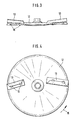
- centrifugal disc 12 shows the arrangement of the throwing elements 13 on the centrifugal disc 12.
- This centrifugal disc 12 is driven in such a rotating manner that it rotates in the direction of arrow 15.
- the centrifugal disc 12 shown here is the centrifugal disc arranged below the right-hand container part 8.
- the throwing elements 13 are fastened on the centrifugal disc 12 by means of the screws 16.
- the centrifugal disks 12 are designed such that they can be removed from their respective drive shaft 11 even when the storage container 6 is full, so that these centrifugal disks 12 can be exchanged for differently designed centrifugal disks.
- the respective throwing elements 13 which consist of an inner part 17 and the outer part 18 which are screwed onto the centrifugal disc 12 with screws 16.
- the respective outer part 18 each has an elongated hole guide 19 which interacts with the bolt 20 welded to the inner part 17.
- the respective throwing element 13, consisting of an inner and an outer part 17, 18, is designed as a telescopically extendable and insertable throwing element 13. This makes it possible to change the distance between the respective discharge edge 21 of the throwing element 13 with respect to the axis of rotation 11 of the centrifugal disc 12. This is done with the aid of the telescopic, extendable and insertable outer part 18, which can be locked in different positions with respect to the inner part 17.
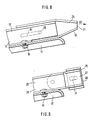
- the type of arrangement of the displaceable outer part 18 in an easily detachable manner on the fixed inner part 17 of the throwing element 13 enables the use of differently designed outer parts 22, 23, 24 and 25.
- the outer part 22 is designed such that the this outer part 22 equipped throwing element 13 is suitable for normal fertilization.
- the outer part 23 according to FIG. 6 is a throwing element 13 with which the late fertilization for cereals can be carried out.
- the throwing element 13 equipped with the outer part 24 according to FIG. 7 is used for border spreading in normal fertilization.
- the outer part 25 according to FIG. 8 is a throwing element 13, which is used for border spreading during late fertilization.
- the fertilizer spreader can be set precisely to the type of fertilizer to be applied, so that there is a spread pattern of uniform spreading strength over the entire spreading width of the centrifugal spreader, which is composed of the individual overlapping individual overlapping sectors of the respective centrifugal discs 12.
- FIGS. 5 to 8 show, compared to FIGS. 5 to 8, a differently designed throwing element 26 which is arranged on the centrifugal disc 12.
- the outer part 27 is pivotable relative to the inner part 28 fastened on the centrifugal disc 12 with the screws 16 and can be locked in different positions.
- the additional throwing element 29 is fastened for special scattering cases in such a way that the additional throwing element 29 can be adjusted and locked telescopically with respect to the pivotable outer part 27 of the throwing element 26.
- the throwing edge 30 of the throwing element 26 can be changed with respect to the axis of rotation 11 of the centrifugal disc 12 in the region predetermined by the elongated hole 31; so that it is also possible here to adapt the spreading width of the centrifugal spreader 1 to the respective application conditions in an advantageous manner.
- the pivotability of the outer part 27 relative to the inner part 28 of the throwing element 26 makes it possible to use the throwing element 26 for all types of fertilization, such as normal fertilizers, late fertilizers, boundary spreading in normal fertilization and boundary spreading in late fertilization.
- the invention also takes into account the driving of the centrifugal discs at different speeds by, for example, change gear or manual transmissions and by means of transmissions with two PTO shaft connections. This enables an even better adjustment of the working widths to the respective conditions of use.
Landscapes
- Life Sciences & Earth Sciences (AREA)
- Soil Sciences (AREA)
- Environmental Sciences (AREA)
- Fertilizing (AREA)
- Grinding Of Cylindrical And Plane Surfaces (AREA)
- Mechanically-Actuated Valves (AREA)
- Extrusion Moulding Of Plastics Or The Like (AREA)
- Electrical Discharge Machining, Electrochemical Machining, And Combined Machining (AREA)
- Pharmaceuticals Containing Other Organic And Inorganic Compounds (AREA)
Priority Applications (1)
| Application Number | Priority Date | Filing Date | Title |
|---|---|---|---|
| AT87105404T ATE61198T1 (de) | 1986-04-22 | 1987-04-11 | Schleuderstreuer. |
Applications Claiming Priority (2)
| Application Number | Priority Date | Filing Date | Title |
|---|---|---|---|
| DE3613540 | 1986-04-22 | ||
| DE19863613540 DE3613540A1 (de) | 1986-04-22 | 1986-04-22 | Schleuderstreuer |
Publications (4)
| Publication Number | Publication Date |
|---|---|
| EP0242749A2 true EP0242749A2 (fr) | 1987-10-28 |
| EP0242749A3 EP0242749A3 (en) | 1988-04-27 |
| EP0242749B1 EP0242749B1 (fr) | 1991-03-06 |
| EP0242749B2 EP0242749B2 (fr) | 1996-05-15 |
Family
ID=6299232
Family Applications (1)
| Application Number | Title | Priority Date | Filing Date |
|---|---|---|---|
| EP87105404A Expired - Lifetime EP0242749B2 (fr) | 1986-04-22 | 1987-04-11 | Distributeur à disques |
Country Status (4)
| Country | Link |
|---|---|
| EP (1) | EP0242749B2 (fr) |
| AT (1) | ATE61198T1 (fr) |
| DE (2) | DE3613540A1 (fr) |
| ES (1) | ES2021294B3 (fr) |
Cited By (3)
| Publication number | Priority date | Publication date | Assignee | Title |
|---|---|---|---|---|
| FR2700660A1 (fr) * | 1993-01-27 | 1994-07-29 | Amazonen Werke Dreyer H | Epandeur centrifuge d'engrais à disque d'épandage rotatif à éjection normale ou limitée. |
| EP1618775A1 (fr) * | 2004-07-21 | 2006-01-25 | Amazonen-Werke H. Dreyer GmbH & Co. KG | Epandeur centrifuge pour engrais |
| CN115571342A (zh) * | 2022-10-03 | 2023-01-06 | 东北农业大学 | 一种搭载于无人机的变量撒肥装置 |
Families Citing this family (3)
| Publication number | Priority date | Publication date | Assignee | Title |
|---|---|---|---|---|
| DE3812087A1 (de) * | 1988-04-12 | 1989-10-26 | Amazonen Werke Dreyer H | Schleuderstreuer |
| DE4328991A1 (de) * | 1993-08-28 | 1995-03-02 | Rauch Landmaschfab Gmbh | Schleuderstreuer |
| KR100330086B1 (ko) | 1999-01-22 | 2002-03-25 | 권영한 | 컷리스 래그 스위치 |
Family Cites Families (4)
| Publication number | Priority date | Publication date | Assignee | Title |
|---|---|---|---|---|
| DE1757834U (de) * | 1957-10-14 | 1957-12-12 | H & W Fritzen Maschf | Duengerstreuer. |
| DE2818227A1 (de) * | 1978-04-26 | 1979-11-08 | Amazonen Werke Dreyer H | Zentrifugalstreuer, insbesondere fuer duengemittel |
| DE2913738A1 (de) * | 1979-04-05 | 1980-10-16 | Amazonen Werke Dreyer H | Verfahren zur veraenderung der streuarbeit von schleuderstreuern |
| DE3015486C2 (de) * | 1980-04-23 | 1985-03-28 | Amazonen-Werke H. Dreyer Gmbh & Co Kg, 4507 Hasbergen | Schleuderstreuer zur Ausbringung von Düngemitteln |
-
1986
- 1986-04-22 DE DE19863613540 patent/DE3613540A1/de not_active Withdrawn
-
1987
- 1987-04-11 EP EP87105404A patent/EP0242749B2/fr not_active Expired - Lifetime
- 1987-04-11 DE DE8787105404T patent/DE3768312D1/de not_active Expired - Lifetime
- 1987-04-11 AT AT87105404T patent/ATE61198T1/de active
- 1987-04-11 ES ES87105404T patent/ES2021294B3/es not_active Expired - Lifetime
Cited By (4)
| Publication number | Priority date | Publication date | Assignee | Title |
|---|---|---|---|---|
| FR2700660A1 (fr) * | 1993-01-27 | 1994-07-29 | Amazonen Werke Dreyer H | Epandeur centrifuge d'engrais à disque d'épandage rotatif à éjection normale ou limitée. |
| EP1618775A1 (fr) * | 2004-07-21 | 2006-01-25 | Amazonen-Werke H. Dreyer GmbH & Co. KG | Epandeur centrifuge pour engrais |
| CN115571342A (zh) * | 2022-10-03 | 2023-01-06 | 东北农业大学 | 一种搭载于无人机的变量撒肥装置 |
| CN115571342B (zh) * | 2022-10-03 | 2024-01-19 | 东北农业大学 | 一种搭载于无人机的变量撒肥装置 |
Also Published As
| Publication number | Publication date |
|---|---|
| EP0242749B1 (fr) | 1991-03-06 |
| EP0242749A3 (en) | 1988-04-27 |
| ES2021294B3 (es) | 1991-11-01 |
| DE3768312D1 (de) | 1991-04-11 |
| ATE61198T1 (de) | 1991-03-15 |
| DE3613540A1 (de) | 1987-10-29 |
| EP0242749B2 (fr) | 1996-05-15 |
Similar Documents
| Publication | Publication Date | Title |
|---|---|---|
| EP0017128A1 (fr) | Distributeur centrifuge pour l'épandage d'engrais ou autre | |
| EP0655187A1 (fr) | Epandeur centrifuge | |
| DE3413944A1 (de) | Schleuderstreuer | |
| EP0242749B1 (fr) | Distributeur à disques | |
| EP0427935B1 (fr) | Procédé à l'usage d'un epandeur d'engrais centrifuge | |
| DE19513423A1 (de) | Schleuderdüngerstreuer | |
| EP0292873B1 (fr) | Méthode d'épandage et de distribution d'engrais | |
| DE4134315A1 (de) | Schleuderduengerstreuer | |
| EP0429864B1 (fr) | Epandeur d'engrais centrifuge | |
| EP0281886B1 (fr) | Epandeur d'engrais centrifuge | |
| EP1031268B1 (fr) | Epandeur d'engrais centrifuge | |
| EP0430927B1 (fr) | Epandeur centrifuge | |
| EP0330920B1 (fr) | Epandeur centrifuge | |
| DE8705447U1 (de) | Schleuderstreuer | |
| EP0292650A1 (fr) | Epandeur d'engrais centrifuge | |
| DE19720561A1 (de) | Verfahren zum Einsatz eines Schleuderstreuers | |
| DE102004039193A1 (de) | Schleuderdüngerstreuer | |
| DE4003945A1 (de) | Schleuderduengerstreuer | |
| DE4302140A1 (de) | Schleuderdüngerstreuer | |
| DE3608935A1 (de) | Schleuderstreuer | |
| EP1090542A2 (fr) | Epandeur centrifuge | |
| EP1372371A2 (fr) | Epandeur d'engrais centrifuge | |
| DE19646590A1 (de) | Schleuderdüngerstreuer | |
| DE3936633A1 (de) | Zentrifugalduengerstreuer | |
| DE4407009A1 (de) | Schleuderstreuer |
Legal Events
| Date | Code | Title | Description |
|---|---|---|---|
| PUAI | Public reference made under article 153(3) epc to a published international application that has entered the european phase |
Free format text: ORIGINAL CODE: 0009012 |
|
| AK | Designated contracting states |
Kind code of ref document: A2 Designated state(s): AT DE ES FR GB IT NL |
|
| PUAL | Search report despatched |
Free format text: ORIGINAL CODE: 0009013 |
|
| AK | Designated contracting states |
Kind code of ref document: A3 Designated state(s): AT DE ES FR GB IT NL |
|
| 17P | Request for examination filed |
Effective date: 19880514 |
|
| 17Q | First examination report despatched |
Effective date: 19891208 |
|
| GRAA | (expected) grant |
Free format text: ORIGINAL CODE: 0009210 |
|
| ITF | It: translation for a ep patent filed | ||
| AK | Designated contracting states |
Kind code of ref document: B1 Designated state(s): AT DE ES FR GB IT NL |
|
| REF | Corresponds to: |
Ref document number: 61198 Country of ref document: AT Date of ref document: 19910315 Kind code of ref document: T |
|
| ET | Fr: translation filed | ||
| GBT | Gb: translation of ep patent filed (gb section 77(6)(a)/1977) | ||
| REF | Corresponds to: |
Ref document number: 3768312 Country of ref document: DE Date of ref document: 19910411 |
|
| PLBI | Opposition filed |
Free format text: ORIGINAL CODE: 0009260 |
|
| PLBI | Opposition filed |
Free format text: ORIGINAL CODE: 0009260 |
|
| 26 | Opposition filed |
Opponent name: RAUCH LANDMASCHINENFABRIK GMBH Effective date: 19911204 |
|
| 26 | Opposition filed |
Opponent name: C. VAN DER LELY N.V. Effective date: 19911205 Opponent name: RAUCH LANDMASCHINENFABRIK GMBH Effective date: 19911204 |
|
| NLR1 | Nl: opposition has been filed with the epo |
Opponent name: C. VAN DER LELY N.V. Opponent name: RAUCH LANDMASCHINENFABRIK GMBH |
|
| PGFP | Annual fee paid to national office [announced via postgrant information from national office to epo] |
Ref country code: ES Payment date: 19930218 Year of fee payment: 7 |
|
| PGFP | Annual fee paid to national office [announced via postgrant information from national office to epo] |
Ref country code: AT Payment date: 19930413 Year of fee payment: 7 |
|
| PG25 | Lapsed in a contracting state [announced via postgrant information from national office to epo] |
Ref country code: AT Effective date: 19940411 |
|
| PG25 | Lapsed in a contracting state [announced via postgrant information from national office to epo] |
Ref country code: ES Free format text: LAPSE BECAUSE OF NON-PAYMENT OF DUE FEES Effective date: 19940412 |
|
| APAC | Appeal dossier modified |
Free format text: ORIGINAL CODE: EPIDOS NOAPO |
|
| PLAW | Interlocutory decision in opposition |
Free format text: ORIGINAL CODE: EPIDOS IDOP |
|
| PUAH | Patent maintained in amended form |
Free format text: ORIGINAL CODE: 0009272 |
|
| STAA | Information on the status of an ep patent application or granted ep patent |
Free format text: STATUS: PATENT MAINTAINED AS AMENDED |
|
| 27A | Patent maintained in amended form |
Effective date: 19960515 |
|
| AK | Designated contracting states |
Kind code of ref document: B2 Designated state(s): AT DE ES FR GB IT NL |
|
| GBTA | Gb: translation of amended ep patent filed (gb section 77(6)(b)/1977) |
Effective date: 19960529 |
|
| ET3 | Fr: translation filed ** decision concerning opposition | ||
| NLR2 | Nl: decision of opposition | ||
| NLR3 | Nl: receipt of modified translations in the netherlands language after an opposition procedure | ||
| REG | Reference to a national code |
Ref country code: ES Ref legal event code: FD2A Effective date: 19990201 |
|
| PGFP | Annual fee paid to national office [announced via postgrant information from national office to epo] |
Ref country code: GB Payment date: 20010207 Year of fee payment: 15 |
|
| PGFP | Annual fee paid to national office [announced via postgrant information from national office to epo] |
Ref country code: NL Payment date: 20010430 Year of fee payment: 15 |
|
| REG | Reference to a national code |
Ref country code: GB Ref legal event code: IF02 |
|
| PG25 | Lapsed in a contracting state [announced via postgrant information from national office to epo] |
Ref country code: GB Free format text: LAPSE BECAUSE OF NON-PAYMENT OF DUE FEES Effective date: 20020411 |
|
| PG25 | Lapsed in a contracting state [announced via postgrant information from national office to epo] |
Ref country code: NL Free format text: LAPSE BECAUSE OF NON-PAYMENT OF DUE FEES Effective date: 20021101 |
|
| GBPC | Gb: european patent ceased through non-payment of renewal fee |
Effective date: 20020411 |
|
| NLV4 | Nl: lapsed or anulled due to non-payment of the annual fee |
Effective date: 20021101 |
|
| PGFP | Annual fee paid to national office [announced via postgrant information from national office to epo] |
Ref country code: DE Payment date: 20030410 Year of fee payment: 17 |
|
| PGFP | Annual fee paid to national office [announced via postgrant information from national office to epo] |
Ref country code: FR Payment date: 20030429 Year of fee payment: 17 |
|
| PG25 | Lapsed in a contracting state [announced via postgrant information from national office to epo] |
Ref country code: DE Free format text: LAPSE BECAUSE OF NON-PAYMENT OF DUE FEES Effective date: 20041103 |
|
| PG25 | Lapsed in a contracting state [announced via postgrant information from national office to epo] |
Ref country code: FR Free format text: LAPSE BECAUSE OF NON-PAYMENT OF DUE FEES Effective date: 20041231 |
|
| REG | Reference to a national code |
Ref country code: FR Ref legal event code: ST |
|
| PG25 | Lapsed in a contracting state [announced via postgrant information from national office to epo] |
Ref country code: IT Free format text: LAPSE BECAUSE OF NON-PAYMENT OF DUE FEES;WARNING: LAPSES OF ITALIAN PATENTS WITH EFFECTIVE DATE BEFORE 2007 MAY HAVE OCCURRED AT ANY TIME BEFORE 2007. THE CORRECT EFFECTIVE DATE MAY BE DIFFERENT FROM THE ONE RECORDED. Effective date: 20050411 |
|
| APAH | Appeal reference modified |
Free format text: ORIGINAL CODE: EPIDOSCREFNO |