EP0242665A2 - Dispositif pour chasser les souillures légèrement volatiles de liquides - Google Patents
Dispositif pour chasser les souillures légèrement volatiles de liquides Download PDFInfo
- Publication number
- EP0242665A2 EP0242665A2 EP87104954A EP87104954A EP0242665A2 EP 0242665 A2 EP0242665 A2 EP 0242665A2 EP 87104954 A EP87104954 A EP 87104954A EP 87104954 A EP87104954 A EP 87104954A EP 0242665 A2 EP0242665 A2 EP 0242665A2
- Authority
- EP
- European Patent Office
- Prior art keywords
- air
- container
- arrangement according
- liquid
- shaft
- Prior art date
- Legal status (The legal status is an assumption and is not a legal conclusion. Google has not performed a legal analysis and makes no representation as to the accuracy of the status listed.)
- Granted
Links
Images

Classifications
-
- B—PERFORMING OPERATIONS; TRANSPORTING
- B01—PHYSICAL OR CHEMICAL PROCESSES OR APPARATUS IN GENERAL
- B01D—SEPARATION
- B01D19/00—Degasification of liquids
- B01D19/0005—Degasification of liquids with one or more auxiliary substances
-
- C—CHEMISTRY; METALLURGY
- C02—TREATMENT OF WATER, WASTE WATER, SEWAGE, OR SLUDGE
- C02F—TREATMENT OF WATER, WASTE WATER, SEWAGE, OR SLUDGE
- C02F1/00—Treatment of water, waste water, or sewage
- C02F1/20—Treatment of water, waste water, or sewage by degassing, i.e. liberation of dissolved gases
Definitions
- the invention relates to an arrangement for expelling volatile impurities from liquids, for example from groundwater, with the aid of air or other gases.
- the invention has for its object to provide an arrangement of the type mentioned, which requires a significantly lower design effort and also a lower energy expenditure without their effectiveness suffering.
- the air intake space can either be arranged on the bottom of the container or a treatment chamber of the container or the shaft or in a nozzle body hanging on floats with an adjustable distance from the liquid level, the interior of which is connected to the outside air via a hose line.
- the arrangement in a nozzle body eliminates the need for complex level regulation in the container or shaft containing the liquid to be cleaned.
- the float keeps the nozzle body at an equal and adjustable distance from the liquid level regardless of the degree of filling of the container or shaft, this distance being relatively small compared to known stripping systems.
- the air receiving space or nozzle body can expediently have a nozzle plate which is adapted to the cross section of the container or shaft and is arranged parallel to the liquid level and on the underside of which the outside air is conducted.
- the hose feed line for the outside air to the nozzle body is kept long enough so that the nozzle body can follow level fluctuations in the liquid level unhindered. It has been shown that the air drawn into the nozzle body circulates when the nozzle body is open at the bottom movement of the liquid in the lower part of the container or shaft triggers, which ensures that the lower liquid rises into the fumigation area of the arrangement.
- a finely adjustable increase in vacuum in the system can also be achieved. Only one vacuum generator (fan) is required in the process, from the pressure-free inclusion of the air bubble above the nozzle plate to the venting in the vacuum, above the water surface.
- a shaft can be formed by a borehole drilled vertically into the ground, which can be at least partially reinforced by a perforated pipe or by sieve rings.
- Groundwater can collect in this shaft and experience has shown that it is increasingly drawn into the shaft due to the negative pressure formed in the free space of the shaft.
- air is drawn into the shaft in the part of the shaft that is free of groundwater and through the soil that bounds the shaft, and at the same time cleaning the soil in the shaft area is achieved, the area around the shaft opening being covered extensively by an air-impermeable film.
- the air extracted by the fan can, advantageously together with a portion of outside air, in a filter upstream or downstream of the fan, e.g. B. activated carbon filter, in which the expelled volatile contaminants are filtered out.
- a filter upstream or downstream of the fan e.g. B. activated carbon filter
- a successive ventilation of partial liquid quantities is expediently provided.
- a container can be subdivided into a treatment chamber under the influence of the fan and into an upstream liquid collection chamber which is connected to the treatment chamber via a lockable downpipe.
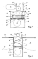
- Fig. 1 shows a collecting container 10, in which the liquid to be cleaned is introduced.
- the liquid level is designated by reference number 11.
- the upper opening 12 of the container 10 can be closed by means of a cover 13, on which a fan 9 is arranged with its suction side above a central opening 14.
- An air intake pipe 16 with an air filter 17 is mounted above a second opening 15 of the cover 13.
- a float ring 18 Arranged in the interior of the container 10 is a float ring 18 which floats on the liquid introduced and on which a nozzle body in the form of a nozzle plate 20 hangs via flexible and adjustable spacers 19, for example chains.
- the nozzle plate 20 has edges 21 which are bent downwards, so that an air space 22 can form below the nozzle plate 20, into which outside air can flow in from the cover opening 15 via a flexible hose 23.
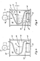
- Fig. 2 shows a modified embodiment of the arrangement of Fig. 1.
- the difference is that in this embodiment, the activated carbon filter 24 ⁇ in the upper part of the container 10 ⁇ and thus on the suction side the attached fan 9 is placed.
- the activated carbon filter 24 ⁇ consists of a bag 40 filled with activated carbon, which is placed on a perforated intermediate wall 39 of the container 10 ⁇ , which simultaneously acts as a droplet separator.
- the outside air is passed through an inlet opening 15 ⁇ arranged on the side of the container 10 ⁇ into the hose line 23 ⁇ .
- the hose line 23 ⁇ has in its initial part openings 38 through which part of the inflowing air enters the space between the liquid level 11 and the perforated intermediate wall 39 and desirably reduces the degree of saturation of the air entering the activated carbon filter 24 ⁇ . Otherwise, the arrangement has the same structure as in the exemplary embodiment according to FIG. 1.
- Fig. 3 shows an arrangement for cleaning groundwater.
- a well 31 In the vicinity of a pollution point, a well 31 is led into the ground 30 to below the groundwater level 32 shown with a broken line.
- the well can be reinforced in a known manner by a perforated tube 37 or by easily assembled sieve rings.
- the nozzle body In the groundwater 33 collecting in the shaft 31, the nozzle body in the form of a nozzle plate 20, which is hanging from a float ring 18 and has already been described in connection with FIG leads.
- a fan 35 is again arranged on the cover 34, by means of which the outside air, which is led via the hose line 23 to the nozzle plate 20, is sucked through the groundwater 33 collected in the shaft and drawn off from the shaft.
- FIG. 4 and 5 show an embodiment in which a nozzle body 41 is arranged immovably in the interior of a container 42 above the bottom 43 thereof.
- the nozzle body 41 again has a nozzle plate 44, which is aligned parallel to the container bottom 43 and to the liquid level 45 of the liquid 46 that is introduced into the container and is to be cleaned, with edges bent downwards and attached in places to the container bottom 43, underneath which there is an air-receiving space as shown in FIG. 5 47 in which, as in the previously described exemplary embodiments, a hose line 23 for the supply of outside air ends.
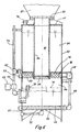
- Fig. 6 shows an embodiment of an arrangement which is intended for the portionwise treatment of larger amounts of liquid.
- the arrangement has a container 52 which is divided by an intermediate floor 53 into a lower treatment chamber 54 and into a liquid collection chamber 55 located above it.
- a concentric tubular body 56 extends upward through the liquid collection chamber 55 from a central opening in the intermediate wall 53 and outwards through a central opening in the roof wall 57 of the container 52.
- the central tubular body 56 is closed at its lower end by a perforated plate 58 and ends at the top in a flange plate 59 on which the suction fan 60, which is only indicated schematically, is placed.
- the interior 61 of the tubular body 56 is filled with activated carbon, thus forming a filter space for the air extracted from the lower treatment chamber 54 by means of the suction fan 60.
- an air-receiving space 67 is formed by a nozzle plate 66 arranged at a distance parallel to the container bottom 65 outer pipe 68, which ends outside the container 52 in a filter basket or a throttle device 69, is connected to the outside air. It is understood that the outer end of the air line 68 lies above the liquid level 71 of the treatment room 54 which is level-controlled by a float switch 70.
- the rivers After cleaning, liquid can flow out of the treatment room 54 through a lower drain line 72.
- the liquid to be cleaned is fed into the liquid collecting space 55 via a pipeline 73 via the three-way valve 62 already mentioned or via an upper pipe connection piece 74.
- the outer pipeline 73 can serve as a vent line and the three-way valve 62 can be omitted.
- a separating space 76 can be formed in the liquid collecting space 55 above the intermediate wall 53 of the container 52, bounded at the top by a perforated plate 75, in which heavier liquid components settle and can be removed from there via a connecting piece 77.
Landscapes
- Chemical & Material Sciences (AREA)
- Chemical Kinetics & Catalysis (AREA)
- Treating Waste Gases (AREA)
- Vaporization, Distillation, Condensation, Sublimation, And Cold Traps (AREA)
- Extraction Or Liquid Replacement (AREA)
- Physical Water Treatments (AREA)
Priority Applications (1)
| Application Number | Priority Date | Filing Date | Title |
|---|---|---|---|
| AT87104954T ATE66161T1 (de) | 1986-04-22 | 1987-04-03 | Anordnung zum austreiben leicht fluechtiger verunreinigungen aus fluessigkeiten. |
Applications Claiming Priority (4)
| Application Number | Priority Date | Filing Date | Title |
|---|---|---|---|
| DE3613518 | 1986-04-22 | ||
| DE3613518 | 1986-04-22 | ||
| DE3625488A DE3625488C2 (de) | 1986-04-22 | 1986-07-28 | Vorrichtung zum Austreiben leicht flüchtiger Verunreinigungen aus Flüssigkeiten |
| DE3625488 | 1986-07-28 |
Publications (4)
| Publication Number | Publication Date |
|---|---|
| EP0242665A2 true EP0242665A2 (fr) | 1987-10-28 |
| EP0242665A3 EP0242665A3 (en) | 1988-08-24 |
| EP0242665B1 EP0242665B1 (fr) | 1991-08-14 |
| EP0242665B2 EP0242665B2 (fr) | 1994-09-21 |
Family
ID=25843098
Family Applications (1)
| Application Number | Title | Priority Date | Filing Date |
|---|---|---|---|
| EP87104954A Expired - Lifetime EP0242665B2 (fr) | 1986-04-22 | 1987-04-03 | Dispositif pour chasser les souillures légèrement volatiles de liquides |
Country Status (4)
| Country | Link |
|---|---|
| US (1) | US4892688A (fr) |
| EP (1) | EP0242665B2 (fr) |
| DE (1) | DE3772090D1 (fr) |
| ES (1) | ES2023839T5 (fr) |
Cited By (4)
| Publication number | Priority date | Publication date | Assignee | Title |
|---|---|---|---|---|
| EP0347576A3 (fr) * | 1988-06-23 | 1991-07-10 | IEG Industrie-Engineering GmbH | Puits avec dispositif pour dégager des impuretés facilement volatiles des eaux souteraines |
| DE4040820A1 (de) * | 1990-05-16 | 1991-11-21 | Hermann Frese | Einrichtung zur reinigung von beispielsweise mit schadstoffen belastetem grundwasser |
| EP0531855A1 (fr) * | 1991-09-05 | 1993-03-17 | Ed. Züblin Aktiengesellschaft | Dispositif pour la purification des eaux souterraines par extraction avec un gaz, en particulier de l'air |
| WO2015162527A1 (fr) | 2014-04-23 | 2015-10-29 | Universita' Degli Studi Di Roma "La Sapienza" | Procédé, agencement et installation pour le nettoyage d'eaux contaminées par des solvants chlorés, des nitrates et des sulfates |
Families Citing this family (11)
| Publication number | Priority date | Publication date | Assignee | Title |
|---|---|---|---|---|
| US5180503A (en) * | 1991-05-10 | 1993-01-19 | The Board Of Trustees Of The Leland Stanford Junior University | In-situ vapor stripping for removing volatile organic compounds from groundwater |
| US5389267A (en) * | 1991-05-10 | 1995-02-14 | The Board Of Trustees Of The Leland Stanford Junior University | In-situ vapor stripping for removing volatile organic compounds from groundwater |
| US5302286A (en) * | 1992-03-17 | 1994-04-12 | The Board Of Trustees Of The Leland Stanford Junior University | Method and apparatus for in situ groundwater remediation |
| US5439594A (en) * | 1993-06-23 | 1995-08-08 | Geraghty & Miller, Inc. | Method for subsurface vapor extraction |
| US5622450A (en) * | 1995-03-24 | 1997-04-22 | Grant, Jr.; Richard P. | Pressure extraction process for removing soil and groundwater contaminants |
| US6143177A (en) * | 1995-04-11 | 2000-11-07 | Arcadis Geraghty & Miller, Inc. | Engineered in situ anaerobic reactive zones |
| US6007274A (en) | 1997-05-19 | 1999-12-28 | Arcadis Geraghty & Miller | In-well air stripping, oxidation, and adsorption |
| US6116816A (en) | 1998-08-26 | 2000-09-12 | Arcadis Geraghty & Miller, Inc. | In situ reactive gate for groundwater remediation |
| AR074096A1 (es) * | 2009-11-10 | 2010-12-22 | Bortolussi Osvaldo Daniel | Dispositivo ecologico/optimizador de combustible para motores de combustion interna que incrementa una masa de aire humedo que ingresa a dicho motor ya sea por succion de vacio o por aspiracion normal |
| US8413966B1 (en) * | 2012-01-19 | 2013-04-09 | Bader Shafaqa Al-Anzi | Water aeration system using renewable energy source |
| AU2018378624B2 (en) * | 2017-12-08 | 2023-09-21 | Eminus, Llc | Enhanced system and method for treatment of soil and groundwater contaminated with PFAS |
Family Cites Families (15)
| Publication number | Priority date | Publication date | Assignee | Title |
|---|---|---|---|---|
| US1305944A (en) * | 1919-06-03 | Humidifier apparatus | ||
| US695125A (en) * | 1900-11-10 | 1902-03-11 | Henry Sue | Apparatus for charging liquids with carbonic-acid gas. |
| US744877A (en) * | 1903-04-15 | 1903-11-24 | Elijah D Parrott | Carbureter. |
| US828494A (en) * | 1905-11-20 | 1906-08-14 | A N Rodgers | Combined water-heater and smoke-consumer. |
| US1708587A (en) * | 1927-05-12 | 1929-04-09 | Patterson Thomas Shaffer | Air washer |
| US3193260A (en) * | 1961-03-13 | 1965-07-06 | Charles M Lamb | Apparatus for aerating and eliminating ice on water |
| DE1642494A1 (de) * | 1967-10-12 | 1972-02-17 | Maerkische Steinkohlengewerksc | Verfahren und Vorrichtung zum Entfernen von in Wasser geloestem Sauerstoff,insbesondere im Zuge der Speisewasseraufbereitung |
| US3498029A (en) * | 1967-10-16 | 1970-03-03 | Louis Feuersanger | Fuel feed system |
| US4045336A (en) * | 1974-08-23 | 1977-08-30 | Pauli Henrik Isteri | Method and device for oxygenating water with vibrations and under pressure strokes |
| DE2522324A1 (de) * | 1975-05-20 | 1976-12-02 | Koolaj Gazipari Tervezo | Verfahren und vorrichtungen zum materialaustausch in gas/fluessigkeits- systemen im gegenstrom |
| US4116488A (en) * | 1976-09-20 | 1978-09-26 | Kennecott Copper Corporation | In-situ mining method and apparatus |
| JPS55500508A (fr) * | 1978-04-06 | 1980-08-14 | ||
| US4365978A (en) * | 1980-03-25 | 1982-12-28 | Shell Oil Company | Storage of liquid hydrocarbons in salt dome caverns |
| DE3501175A1 (de) * | 1985-01-16 | 1986-07-17 | Franz-Josef Dipl.-Ing. 4791 Lichtenau Damann | Verfahren und vorrichtung zur mischung und loesung von gas in fluessigkeit |
| US4624626A (en) * | 1985-03-08 | 1986-11-25 | Sherfinski & Raasch Water Systems, Inc. | Venturi odor dissipator |
-
1987
- 1987-04-03 DE DE8787104954T patent/DE3772090D1/de not_active Expired - Fee Related
- 1987-04-03 EP EP87104954A patent/EP0242665B2/fr not_active Expired - Lifetime
- 1987-04-03 ES ES87104954T patent/ES2023839T5/es not_active Expired - Lifetime
-
1988
- 1988-07-08 US US07/216,942 patent/US4892688A/en not_active Expired - Lifetime
Cited By (4)
| Publication number | Priority date | Publication date | Assignee | Title |
|---|---|---|---|---|
| EP0347576A3 (fr) * | 1988-06-23 | 1991-07-10 | IEG Industrie-Engineering GmbH | Puits avec dispositif pour dégager des impuretés facilement volatiles des eaux souteraines |
| DE4040820A1 (de) * | 1990-05-16 | 1991-11-21 | Hermann Frese | Einrichtung zur reinigung von beispielsweise mit schadstoffen belastetem grundwasser |
| EP0531855A1 (fr) * | 1991-09-05 | 1993-03-17 | Ed. Züblin Aktiengesellschaft | Dispositif pour la purification des eaux souterraines par extraction avec un gaz, en particulier de l'air |
| WO2015162527A1 (fr) | 2014-04-23 | 2015-10-29 | Universita' Degli Studi Di Roma "La Sapienza" | Procédé, agencement et installation pour le nettoyage d'eaux contaminées par des solvants chlorés, des nitrates et des sulfates |
Also Published As
| Publication number | Publication date |
|---|---|
| EP0242665B1 (fr) | 1991-08-14 |
| EP0242665A3 (en) | 1988-08-24 |
| US4892688A (en) | 1990-01-09 |
| EP0242665B2 (fr) | 1994-09-21 |
| ES2023839B3 (es) | 1992-02-16 |
| ES2023839T5 (es) | 1995-08-16 |
| DE3772090D1 (de) | 1991-09-19 |
Similar Documents
| Publication | Publication Date | Title |
|---|---|---|
| DE3625488C2 (de) | Vorrichtung zum Austreiben leicht flüchtiger Verunreinigungen aus Flüssigkeiten | |
| EP0418572B1 (fr) | Dispositif pour chasser des polluants volatiles légers de la nappe souterraine | |
| EP0486976B1 (fr) | Dispositif pour la pourification des eaux souterraines polluées | |
| EP0472967B1 (fr) | Dispositif pour retirer des polluants volatisables de l'eau souterraine | |
| EP0242665B1 (fr) | Dispositif pour chasser les souillures légèrement volatiles de liquides | |
| EP0328993B1 (fr) | Dispositif pour chasser les souillures légèrement volatiles de la nappe souterraine | |
| DE69824878T2 (de) | Methode und vorrichtung zum abtrennen von schwimmenden schmutzstoffen | |
| DE3026519A1 (de) | Schwimmende wasserreinigungseinrichtung | |
| EP0572818A1 (fr) | Procédé et dispositif pour rincer des polluants présents dans le sol | |
| DE3506687A1 (de) | Verfahren und vorrichtung zur biologischen reinigung von abwasser | |
| WO1990011811A1 (fr) | Dispositif pour expulser des impuretes volatiles de la nappe souterraine | |
| DE3811962C1 (en) | Arrangement for expelling highly volatile impurities from ground water | |
| DE3244539C2 (de) | Vorrichtung zur Reinhaltung von Regenüberlaufbecken oder Regenrückhaltebecken | |
| DE2705732C3 (de) | Naßabscheider | |
| DE2502694A1 (de) | Vorrichtung und verfahren zur ueberwachung der verunreinigung von daempfen oder gasen | |
| WO1995024280A1 (fr) | Procede et dispositif permettant d'eliminer des impuretes liquides peu volatiles de faible masse volumique, presentes sous forme d'eau, contenues dans des sols parcourus par les eaux souterraines | |
| DE1947229A1 (de) | Aktivkohle-Austrags-Vorrichtung | |
| DE2728124C3 (de) | Vorrichtung zur Abscheidung von staubtörmigen Teilen aus einem Luftstrom | |
| DE69002348T2 (de) | Vorrichtung und verfahren fuer eine kombinierte luft- und wasserreinigung. | |
| DE60126738T2 (de) | Filterbeutelvorrichtung | |
| DE4102167A1 (de) | Verfahren zur biologischen behandlung von abgasen und einrichtung zur ausfuehrung des verfahrens | |
| DE2303396A1 (de) | Verfahren zum loesen eines gases oder einer gaskomponente in einer fluessigkeit | |
| DE8620217U1 (de) | Vorrichtung zum Austreiben leicht flüchtiger Verunreinigungen aus Flüssigkeiten | |
| DE2634644A1 (de) | Nassreinigungsverfahren und -vorrichtung | |
| DE19516596C2 (de) | Vorrichtung zur Behandlung von gasbildenden stehenden Gewässern |
Legal Events
| Date | Code | Title | Description |
|---|---|---|---|
| PUAI | Public reference made under article 153(3) epc to a published international application that has entered the european phase |
Free format text: ORIGINAL CODE: 0009012 |
|
| AK | Designated contracting states |
Kind code of ref document: A2 Designated state(s): AT CH DE ES FR GB IT LI NL SE |
|
| PUAL | Search report despatched |
Free format text: ORIGINAL CODE: 0009013 |
|
| AK | Designated contracting states |
Kind code of ref document: A3 Designated state(s): AT CH DE ES FR GB IT LI NL SE |
|
| 17P | Request for examination filed |
Effective date: 19881119 |
|
| 17Q | First examination report despatched |
Effective date: 19901002 |
|
| GRAA | (expected) grant |
Free format text: ORIGINAL CODE: 0009210 |
|
| AK | Designated contracting states |
Kind code of ref document: B1 Designated state(s): AT CH DE ES FR GB IT LI NL SE |
|
| REF | Corresponds to: |
Ref document number: 66161 Country of ref document: AT Date of ref document: 19910815 Kind code of ref document: T |
|
| REF | Corresponds to: |
Ref document number: 3772090 Country of ref document: DE Date of ref document: 19910919 |
|
| ET | Fr: translation filed | ||
| ITF | It: translation for a ep patent filed | ||
| GBT | Gb: translation of ep patent filed (gb section 77(6)(a)/1977) | ||
| PLBI | Opposition filed |
Free format text: ORIGINAL CODE: 0009260 |
|
| PLAB | Opposition data, opponent's data or that of the opponent's representative modified |
Free format text: ORIGINAL CODE: 0009299OPPO |
|
| 26 | Opposition filed |
Opponent name: ED. ZUEBLIN AG Effective date: 19920512 |
|
| R26 | Opposition filed (corrected) |
Opponent name: ED. ZUEBLIN AG Effective date: 19920512 |
|
| NLR1 | Nl: opposition has been filed with the epo |
Opponent name: ED.ZUBLIN AG |
|
| PUAA | Information related to the publication of a b2 document modified |
Free format text: ORIGINAL CODE: 0009299PMAP |
|
| PUAH | Patent maintained in amended form |
Free format text: ORIGINAL CODE: 0009272 |
|
| STAA | Information on the status of an ep patent application or granted ep patent |
Free format text: STATUS: PATENT MAINTAINED AS AMENDED |
|
| 27A | Patent maintained in amended form |
Effective date: 19940921 |
|
| AK | Designated contracting states |
Kind code of ref document: B2 Designated state(s): SE |
|
| GBTA | Gb: translation of amended ep patent filed (gb section 77(6)(b)/1977) |
Effective date: 19940907 |
|
| R27A | Patent maintained in amended form (corrected) |
Effective date: 19940921 |
|
| REG | Reference to a national code |
Ref country code: CH Ref legal event code: AEN |
|
| NLR2 | Nl: decision of opposition | ||
| NLR3 | Nl: receipt of modified translations in the netherlands language after an opposition procedure | ||
| ET3 | Fr: translation filed ** decision concerning opposition | ||
| ITF | It: translation for a ep patent filed | ||
| EAL | Se: european patent in force in sweden |
Ref document number: 87104954.0 |
|
| PGFP | Annual fee paid to national office [announced via postgrant information from national office to epo] |
Ref country code: CH Payment date: 19950303 Year of fee payment: 9 |
|
| PGFP | Annual fee paid to national office [announced via postgrant information from national office to epo] |
Ref country code: SE Payment date: 19950307 Year of fee payment: 9 |
|
| PGFP | Annual fee paid to national office [announced via postgrant information from national office to epo] |
Ref country code: GB Payment date: 19950324 Year of fee payment: 9 |
|
| PGFP | Annual fee paid to national office [announced via postgrant information from national office to epo] |
Ref country code: ES Payment date: 19950328 Year of fee payment: 9 |
|
| PGFP | Annual fee paid to national office [announced via postgrant information from national office to epo] |
Ref country code: FR Payment date: 19950329 Year of fee payment: 9 |
|
| PGFP | Annual fee paid to national office [announced via postgrant information from national office to epo] |
Ref country code: AT Payment date: 19950428 Year of fee payment: 9 |
|
| PGFP | Annual fee paid to national office [announced via postgrant information from national office to epo] |
Ref country code: NL Payment date: 19950430 Year of fee payment: 9 |
|
| REG | Reference to a national code |
Ref country code: ES Ref legal event code: DC2A Kind code of ref document: T5 Effective date: 19950816 |
|
| PG25 | Lapsed in a contracting state [announced via postgrant information from national office to epo] |
Ref country code: GB Effective date: 19960403 Ref country code: AT Effective date: 19960403 |
|
| PG25 | Lapsed in a contracting state [announced via postgrant information from national office to epo] |
Ref country code: SE Effective date: 19960404 |
|
| PG25 | Lapsed in a contracting state [announced via postgrant information from national office to epo] |
Ref country code: ES Free format text: LAPSE BECAUSE OF NON-PAYMENT OF DUE FEES Effective date: 19960406 |
|
| PG25 | Lapsed in a contracting state [announced via postgrant information from national office to epo] |
Ref country code: LI Effective date: 19960430 Ref country code: CH Effective date: 19960430 |
|
| PG25 | Lapsed in a contracting state [announced via postgrant information from national office to epo] |
Ref country code: NL Effective date: 19961101 |
|
| GBPC | Gb: european patent ceased through non-payment of renewal fee |
Effective date: 19960403 |
|
| REG | Reference to a national code |
Ref country code: CH Ref legal event code: PL |
|
| PG25 | Lapsed in a contracting state [announced via postgrant information from national office to epo] |
Ref country code: FR Effective date: 19961227 |
|
| NLV4 | Nl: lapsed or anulled due to non-payment of the annual fee |
Effective date: 19961101 |
|
| EUG | Se: european patent has lapsed |
Ref document number: 87104954.0 |
|
| REG | Reference to a national code |
Ref country code: FR Ref legal event code: ST |
|
| REG | Reference to a national code |
Ref country code: CH Ref legal event code: AEN Free format text: AUFRECHTERHALTUNG DES PATENTES IN GEAENDERTER FORM |
|
| REG | Reference to a national code |
Ref country code: ES Ref legal event code: FD2A Effective date: 19990301 |
|
| PGFP | Annual fee paid to national office [announced via postgrant information from national office to epo] |
Ref country code: DE Payment date: 20020408 Year of fee payment: 16 |
|
| PG25 | Lapsed in a contracting state [announced via postgrant information from national office to epo] |
Ref country code: DE Free format text: LAPSE BECAUSE OF NON-PAYMENT OF DUE FEES Effective date: 20031101 |
|
| PG25 | Lapsed in a contracting state [announced via postgrant information from national office to epo] |
Ref country code: IT Free format text: LAPSE BECAUSE OF NON-PAYMENT OF DUE FEES;WARNING: LAPSES OF ITALIAN PATENTS WITH EFFECTIVE DATE BEFORE 2007 MAY HAVE OCCURRED AT ANY TIME BEFORE 2007. THE CORRECT EFFECTIVE DATE MAY BE DIFFERENT FROM THE ONE RECORDED. Effective date: 20050403 |