EP0242665A2 - Apparatus for the expulsion of light volatile pollutants from liquids - Google Patents
Apparatus for the expulsion of light volatile pollutants from liquids Download PDFInfo
- Publication number
- EP0242665A2 EP0242665A2 EP87104954A EP87104954A EP0242665A2 EP 0242665 A2 EP0242665 A2 EP 0242665A2 EP 87104954 A EP87104954 A EP 87104954A EP 87104954 A EP87104954 A EP 87104954A EP 0242665 A2 EP0242665 A2 EP 0242665A2
- Authority
- EP
- European Patent Office
- Prior art keywords
- air
- container
- arrangement according
- liquid
- shaft
- Prior art date
- Legal status (The legal status is an assumption and is not a legal conclusion. Google has not performed a legal analysis and makes no representation as to the accuracy of the status listed.)
- Granted
Links
Images

Classifications
-
- B—PERFORMING OPERATIONS; TRANSPORTING
- B01—PHYSICAL OR CHEMICAL PROCESSES OR APPARATUS IN GENERAL
- B01D—SEPARATION
- B01D19/00—Degasification of liquids
- B01D19/0005—Degasification of liquids with one or more auxiliary substances
-
- C—CHEMISTRY; METALLURGY
- C02—TREATMENT OF WATER, WASTE WATER, SEWAGE, OR SLUDGE
- C02F—TREATMENT OF WATER, WASTE WATER, SEWAGE, OR SLUDGE
- C02F1/00—Treatment of water, waste water, or sewage
- C02F1/20—Treatment of water, waste water, or sewage by degassing, i.e. liberation of dissolved gases
Definitions
- the invention relates to an arrangement for expelling volatile impurities from liquids, for example from groundwater, with the aid of air or other gases.
- the invention has for its object to provide an arrangement of the type mentioned, which requires a significantly lower design effort and also a lower energy expenditure without their effectiveness suffering.
- the air intake space can either be arranged on the bottom of the container or a treatment chamber of the container or the shaft or in a nozzle body hanging on floats with an adjustable distance from the liquid level, the interior of which is connected to the outside air via a hose line.
- the arrangement in a nozzle body eliminates the need for complex level regulation in the container or shaft containing the liquid to be cleaned.
- the float keeps the nozzle body at an equal and adjustable distance from the liquid level regardless of the degree of filling of the container or shaft, this distance being relatively small compared to known stripping systems.
- the air receiving space or nozzle body can expediently have a nozzle plate which is adapted to the cross section of the container or shaft and is arranged parallel to the liquid level and on the underside of which the outside air is conducted.
- the hose feed line for the outside air to the nozzle body is kept long enough so that the nozzle body can follow level fluctuations in the liquid level unhindered. It has been shown that the air drawn into the nozzle body circulates when the nozzle body is open at the bottom movement of the liquid in the lower part of the container or shaft triggers, which ensures that the lower liquid rises into the fumigation area of the arrangement.
- a finely adjustable increase in vacuum in the system can also be achieved. Only one vacuum generator (fan) is required in the process, from the pressure-free inclusion of the air bubble above the nozzle plate to the venting in the vacuum, above the water surface.
- a shaft can be formed by a borehole drilled vertically into the ground, which can be at least partially reinforced by a perforated pipe or by sieve rings.
- Groundwater can collect in this shaft and experience has shown that it is increasingly drawn into the shaft due to the negative pressure formed in the free space of the shaft.
- air is drawn into the shaft in the part of the shaft that is free of groundwater and through the soil that bounds the shaft, and at the same time cleaning the soil in the shaft area is achieved, the area around the shaft opening being covered extensively by an air-impermeable film.
- the air extracted by the fan can, advantageously together with a portion of outside air, in a filter upstream or downstream of the fan, e.g. B. activated carbon filter, in which the expelled volatile contaminants are filtered out.
- a filter upstream or downstream of the fan e.g. B. activated carbon filter
- a successive ventilation of partial liquid quantities is expediently provided.
- a container can be subdivided into a treatment chamber under the influence of the fan and into an upstream liquid collection chamber which is connected to the treatment chamber via a lockable downpipe.
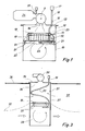
- Fig. 1 shows a collecting container 10, in which the liquid to be cleaned is introduced.
- the liquid level is designated by reference number 11.
- the upper opening 12 of the container 10 can be closed by means of a cover 13, on which a fan 9 is arranged with its suction side above a central opening 14.
- An air intake pipe 16 with an air filter 17 is mounted above a second opening 15 of the cover 13.
- a float ring 18 Arranged in the interior of the container 10 is a float ring 18 which floats on the liquid introduced and on which a nozzle body in the form of a nozzle plate 20 hangs via flexible and adjustable spacers 19, for example chains.
- the nozzle plate 20 has edges 21 which are bent downwards, so that an air space 22 can form below the nozzle plate 20, into which outside air can flow in from the cover opening 15 via a flexible hose 23.
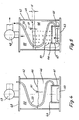
- Fig. 2 shows a modified embodiment of the arrangement of Fig. 1.
- the difference is that in this embodiment, the activated carbon filter 24 ⁇ in the upper part of the container 10 ⁇ and thus on the suction side the attached fan 9 is placed.
- the activated carbon filter 24 ⁇ consists of a bag 40 filled with activated carbon, which is placed on a perforated intermediate wall 39 of the container 10 ⁇ , which simultaneously acts as a droplet separator.
- the outside air is passed through an inlet opening 15 ⁇ arranged on the side of the container 10 ⁇ into the hose line 23 ⁇ .
- the hose line 23 ⁇ has in its initial part openings 38 through which part of the inflowing air enters the space between the liquid level 11 and the perforated intermediate wall 39 and desirably reduces the degree of saturation of the air entering the activated carbon filter 24 ⁇ . Otherwise, the arrangement has the same structure as in the exemplary embodiment according to FIG. 1.
- Fig. 3 shows an arrangement for cleaning groundwater.
- a well 31 In the vicinity of a pollution point, a well 31 is led into the ground 30 to below the groundwater level 32 shown with a broken line.
- the well can be reinforced in a known manner by a perforated tube 37 or by easily assembled sieve rings.
- the nozzle body In the groundwater 33 collecting in the shaft 31, the nozzle body in the form of a nozzle plate 20, which is hanging from a float ring 18 and has already been described in connection with FIG leads.
- a fan 35 is again arranged on the cover 34, by means of which the outside air, which is led via the hose line 23 to the nozzle plate 20, is sucked through the groundwater 33 collected in the shaft and drawn off from the shaft.
- FIG. 4 and 5 show an embodiment in which a nozzle body 41 is arranged immovably in the interior of a container 42 above the bottom 43 thereof.
- the nozzle body 41 again has a nozzle plate 44, which is aligned parallel to the container bottom 43 and to the liquid level 45 of the liquid 46 that is introduced into the container and is to be cleaned, with edges bent downwards and attached in places to the container bottom 43, underneath which there is an air-receiving space as shown in FIG. 5 47 in which, as in the previously described exemplary embodiments, a hose line 23 for the supply of outside air ends.
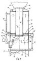
- Fig. 6 shows an embodiment of an arrangement which is intended for the portionwise treatment of larger amounts of liquid.
- the arrangement has a container 52 which is divided by an intermediate floor 53 into a lower treatment chamber 54 and into a liquid collection chamber 55 located above it.
- a concentric tubular body 56 extends upward through the liquid collection chamber 55 from a central opening in the intermediate wall 53 and outwards through a central opening in the roof wall 57 of the container 52.
- the central tubular body 56 is closed at its lower end by a perforated plate 58 and ends at the top in a flange plate 59 on which the suction fan 60, which is only indicated schematically, is placed.
- the interior 61 of the tubular body 56 is filled with activated carbon, thus forming a filter space for the air extracted from the lower treatment chamber 54 by means of the suction fan 60.
- an air-receiving space 67 is formed by a nozzle plate 66 arranged at a distance parallel to the container bottom 65 outer pipe 68, which ends outside the container 52 in a filter basket or a throttle device 69, is connected to the outside air. It is understood that the outer end of the air line 68 lies above the liquid level 71 of the treatment room 54 which is level-controlled by a float switch 70.
- the rivers After cleaning, liquid can flow out of the treatment room 54 through a lower drain line 72.
- the liquid to be cleaned is fed into the liquid collecting space 55 via a pipeline 73 via the three-way valve 62 already mentioned or via an upper pipe connection piece 74.
- the outer pipeline 73 can serve as a vent line and the three-way valve 62 can be omitted.
- a separating space 76 can be formed in the liquid collecting space 55 above the intermediate wall 53 of the container 52, bounded at the top by a perforated plate 75, in which heavier liquid components settle and can be removed from there via a connecting piece 77.
Landscapes
- Chemical & Material Sciences (AREA)
- Chemical Kinetics & Catalysis (AREA)
- Treating Waste Gases (AREA)
- Extraction Or Liquid Replacement (AREA)
- Vaporization, Distillation, Condensation, Sublimation, And Cold Traps (AREA)
- Physical Water Treatments (AREA)
Abstract
Bei der Anordnung wird Luft zur Aufnahme leicht flüchtiger Verunreinigungen durch die zu reinigende Flüssigkeit hindurchgesaugt, wobei durch Ünterdruckbildung oberhalb des Flüssigkeitsspiegels (11) Luft in einen unterhalb des Flüssigkeitsspiegels (11) angeordneten Luftaufnahmeraum, der durch eine Siebwandung vom Flüssigkeitsraum abgegrenzt ist, beispielsweise in einen an einem Schwimmer (18) in der Flüssigkeit hängenden Düsenkörper (20), nachgesaugt wird. 
Description
Die Erfindung betrifft eine Anordnung zum Austreiben leicht flüchtiger Verunreinigungen aus Flüssigkeiten, beispielsweise aus dem Grundwasser, mit Hilfe von Luft oder anderen Gasen.The invention relates to an arrangement for expelling volatile impurities from liquids, for example from groundwater, with the aid of air or other gases.
Es ist bereits bekannt, Abwässer mittels Luft zu begasen, um leicht flüchtige Verunreinigungen, beispielsweise chemische Lösungsmittel, auszutreiben. Die hierbei verwendeten Anordnungen und Vorrichtungen sind aber konstruktiv sehr aufwendig. Beispielsweise wird die zu reinigende Flüssigkeit über Rieselkörper geleitet, die in einem Frischluft-Gegenstrom liegen, oder das Wasser wird über mehrere Kaskaden geleitet, in deren Bereich Druckluft in das Wasser eingepreßt wird. Bei den meisten Einrichtungen wird mit erheblichem Energieaufwand Druckluft durch eine Wassersäule oder eine Wasserschicht hindurchgeleitet, wobei für eine einwandfreie Belüftung eine Regelung des Flüssigkeitsniveaus erforderlich ist. Wegen der Druckabnahme nach oben vergrößern sich die Luftblasen beim Durchgang und begünstigen dadurch eine unerwünschte Schaumbildung in der Flüssigkeit.It is already known to gas waste water using air in order to drive off volatile impurities, for example chemical solvents. The arrangements and devices used here are structurally very complex. For example, the liquid to be cleaned is passed over trickling bodies which are in a fresh air countercurrent, or the water is passed over several cascades, in the area of which compressed air is pressed into the water. In most facilities, compressed air is passed through a water column or a layer of water with considerable expenditure of energy, with a regulation of the for perfect ventilation Liquid levels are required. Due to the decrease in pressure upwards, the air bubbles enlarge as they pass through, thereby promoting undesirable foam formation in the liquid.
Der Erfindung liegt die Aufgabe zugrunde, eine Anordnung der genannten Art zu schaffen, die einen wesentlich geringeren konstruktiven Aufwand und auch einen geringeren Energieaufwand erfordert, ohne daß darunter ihre Wirksamkeit leidet.The invention has for its object to provide an arrangement of the type mentioned, which requires a significantly lower design effort and also a lower energy expenditure without their effectiveness suffering.
Die gestellte Aufgabe wird mit einer Anordnung der eingangs genannten Art erfindungsgemäß durch die in kennzeichnenden Teil des Hauptanspruches aufgeführten Merkmale gelöst.The object is achieved with an arrangement of the type mentioned in the invention by the features listed in the characterizing part of the main claim.
Durch den einen Unterdruck oberhalb des Flüssigkeitsspiegels schaffenden Absaugventilator wird Außenluft als sogenannte Strippluft in den Luftaufnahmeraum nachgezogen, die durch die Siebwandung und durch die Flüssigkeit hindurch zum Flüssigkeitsspiegel aufsteigt. Die von außen angesaugte Strippluft oder ein anderes Trägergas, beispielsweise Stickstoff, kommt erst beim Durchgang durch die Flüssigkeit in Form von Unterdruckbläschen in Kontakt mit den Verunreinigungen, insbesondere Chlorkohlenwasserstoffen, wobei an der Bläschenoberfläche neben der normalen Diffundierwirkung durch den Unterdruck noch eine Ansaugwirkung auftritt. Im gesamten Verfahrensbereich ergeben sich keine Überdrücke durch Strömungs- oder Massendrücke, die den Verdampfungsdrücken entgegenwirken. Die sich über den gesamten Behälterquerschnitt erstreckende Siebwandung sorgt auch für ein Bestreichen der Behälterwände mit Luft.Due to the suction fan creating a negative pressure above the liquid level, outside air is drawn into the air receiving space as so-called stripping air, which rises through the screen wall and through the liquid to the liquid level. The stripping air sucked in from the outside or another carrier gas, for example nitrogen, only comes into contact with the impurities, in particular chlorinated hydrocarbons, when it passes through the liquid in the form of vacuum bubbles, whereby a suction effect also occurs on the surface of the bubble in addition to the normal diffusion effect due to the vacuum. In the entire process area there are no overpressures due to flow or mass pressures which counteract the evaporation pressures. The sieve wall, which extends over the entire cross-section of the container, also ensures that the container walls are coated with air.
Der Luftaufnahmeraum kann entweder am Boden des Behälters oder einer Behandlungskammer des Behälters oder des Schachtes oder aber in einem an Schwimmern mit einstellbarem Abstand vom Flüssigkeitsspiegel hängenden Düsenkörper, dessen Inneres über eine Schlauchleitung mit der Außenluft verbunden ist, angeordnet sein. Bei der Anordnung in einem Düsenkörper entfällt eine aufwendige Niveauregulierung in dem die zu reinigende Flüssigkeit enthaltenden Behälter oder Schacht. Durch den Schwimmer wird der Düsenkörper unabhängig vom Befüllungsgrad des Behälters oder Schachtes immer in einem gleichen und einstellbaren Abstand zum Flüssigkeitsspiegel gehalten, wobei dieser Abstand im Vergleich zu bekannten Strippanlagen relativ klein ist.The air intake space can either be arranged on the bottom of the container or a treatment chamber of the container or the shaft or in a nozzle body hanging on floats with an adjustable distance from the liquid level, the interior of which is connected to the outside air via a hose line. The arrangement in a nozzle body eliminates the need for complex level regulation in the container or shaft containing the liquid to be cleaned. The float keeps the nozzle body at an equal and adjustable distance from the liquid level regardless of the degree of filling of the container or shaft, this distance being relatively small compared to known stripping systems.
Für das Absaugen der Luft und die Unterdruckbildung zum Betrieb der Anordnung wird weniger Energie erforderlich, als bei den mit Druckluft arbeitenden bekannten Begasungseinrichtungen. Der Wirkungsgrad ist so groß, daß auf diese Weise nicht nur Chlorkohlenwasserstoffe, sondern auch andere Kohlenwasserstoffe, Alkohole und Benzolgruppen entfernt werden können.Less energy is required to draw off the air and to form a vacuum to operate the arrangement than in the known gassing devices which work with compressed air. The efficiency is so great that not only chlorinated hydrocarbons, but also other hydrocarbons, alcohols and benzene groups can be removed in this way.
Der Luftaufnahmeraum oder Düsenkörper kann zweckmäßig eine dem Querschnitt des Behälters oder Schachtes angepaßte und parallel zum Flüssigkeitsspiegel angeordnete Düsenplatte aufweisen, auf deren Unterseite die Außenluft geleitet wird. Bei einem schwebenden Düsenkörper wird die Schlauchzuleitung für die Außenluft zum Düsenkörper ausreichend lang gehalten, so daß der Düsenkörper ungehindert Niveauschwankungen des Flüssigkeitsspiegels folgen kann. Es hat sich gezeigt, daß die in den Düsenkörper nachgezogene Luft bei einem nach unten offenen Düsenkörper eine Umwälzbe wegung der Flüssigkeit im unteren Behälter- oder Schachtteil auslöst, die für ein Aufsteigen der unteren Flüssigkeit in den Begasungsbereich der Anordnung sorgt. Durch eine Drosselung der Luftzuleitung kann zusätzlich eine fein abstimmbare Unterdruckerhöhung im System erzielt werden. Im Verfahren ist stets nur ein Unterdruckerzeuger (Ventilator) vom drucklosen Einschluß der Luftblase oberhalb der Düsenplatte bis zur Entlüftung im Unterdruck, oberhalb der Wasserfläche, erforderlich.The air receiving space or nozzle body can expediently have a nozzle plate which is adapted to the cross section of the container or shaft and is arranged parallel to the liquid level and on the underside of which the outside air is conducted. In the case of a floating nozzle body, the hose feed line for the outside air to the nozzle body is kept long enough so that the nozzle body can follow level fluctuations in the liquid level unhindered. It has been shown that the air drawn into the nozzle body circulates when the nozzle body is open at the bottom movement of the liquid in the lower part of the container or shaft triggers, which ensures that the lower liquid rises into the fumigation area of the arrangement. By throttling the air supply line, a finely adjustable increase in vacuum in the system can also be achieved. Only one vacuum generator (fan) is required in the process, from the pressure-free inclusion of the air bubble above the nozzle plate to the venting in the vacuum, above the water surface.
Zur Grundwasserreinigung kann ein Schacht durch ein ins Erdreich vertikal eingebrachtes Bohrloch gebildet werden, das mindestens teilweise durch ein gelochtes Rohr oder durch Siebringe armiert sein kann. In diesem Schacht kann sich Grundwasser sammeln und wird erfahrungsgemäß durch den im Freiraum des Schachtes ausgebildeten Unterdruck verstärkt in den Schacht eingezogen. Gleichzeitig wird im vom Grundwasser freien Teil des Schachtes auch durch das den Schacht begrenzende Erdreich hindurch Luft in den Schacht eingezogen und gleichzeitig eine Reinigung des Erdreichs im Schachtbereich erzielt, wobei die Umgebung der Schachtöffnung weitflächig mittels einer luftundurchlässigen Folie abgedeckt wird.For groundwater purification, a shaft can be formed by a borehole drilled vertically into the ground, which can be at least partially reinforced by a perforated pipe or by sieve rings. Groundwater can collect in this shaft and experience has shown that it is increasingly drawn into the shaft due to the negative pressure formed in the free space of the shaft. At the same time, air is drawn into the shaft in the part of the shaft that is free of groundwater and through the soil that bounds the shaft, and at the same time cleaning the soil in the shaft area is achieved, the area around the shaft opening being covered extensively by an air-impermeable film.
Die durch den Ventilator abgesaugte Luft kann, vorteilhafterweise zusammen mit einem Anteil Außenluft, in ein dem Ventilator vor- oder nachgeschaltetes Filter, z. B. Aktivkohlefilter, geleitet werden, in welchem die ausgetriebenen flüchtigen Verunreinigungen ausgefiltert werden.The air extracted by the fan can, advantageously together with a portion of outside air, in a filter upstream or downstream of the fan, e.g. B. activated carbon filter, in which the expelled volatile contaminants are filtered out.
Wo größere zu reinigende Flüssigkeitsmengen anfallen, wird zweckmäßig eine aufeinanderfolgende Belüftung von Flüssigkeitsteilmengen vorgesehen. Hierzu kann vorteilhafterweise ein Behälter in eine unter der Einwirkung des Ventilators stehende Behandlungskammer und in eine vorgeschaltete Flüssigkeitssammelkammer, die über eine absperrbare Fallleitung mit der Behandlungskammer verbunden ist, unterteilt sein.Where larger quantities of liquid to be cleaned are obtained, a successive ventilation of partial liquid quantities is expediently provided. This can advantageously a container can be subdivided into a treatment chamber under the influence of the fan and into an upstream liquid collection chamber which is connected to the treatment chamber via a lockable downpipe.
Nachfolgend werden mehrere Ausführungsbeispiele einer erfindungsgemäß ausgebildeten Anordnung anhand der beiliegenden schematischen Zeichnung näher erläutert.Several exemplary embodiments of an arrangement designed according to the invention are explained in more detail below with the aid of the attached schematic drawing.
Im einzelnen zeigen:
- Fig. 1 einen schematisierten Längsschnitt durch eine erste, einen Flüssigkeits-Sammelbehälter mit Düsenkörper aufweisende Ausführungsform der Anordnung;
- Fig. 2 eine abgewandelte Ausführungsform der Anordnung nach Fig. 1;
- Fig. 3 eine zweite Ausführungsform der Anordnung mit einem ins Erdreich vertikal eingebrachten Bohrschacht als Grundwasser-Sammelraum;
- Fig. 4 + 5 schematisierte Längsschnitte durch eine dritte Ausführungsform der Anordnung mit einem an einem Behälterboden fest ausgebildeten Luftaufnahmeraum, in Ruhestellung und in Betriebsstellung;
- Fig. 6 einen Längsschnitt durch ein viertes Ausführungsbeispiel der Anordnung.
- 1 shows a schematic longitudinal section through a first embodiment of the arrangement having a liquid collecting container with a nozzle body;
- FIG. 2 shows a modified embodiment of the arrangement according to FIG. 1;
- 3 shows a second embodiment of the arrangement with a drill shaft vertically introduced into the ground as a groundwater collecting space;
- Fig. 4 + 5 schematic longitudinal sections through a third embodiment of the arrangement with an air receiving space fixed to a container bottom, in the rest position and in the operating position;
- Fig. 6 shows a longitudinal section through a fourth embodiment of the arrangement.
Fig. 1 zeigt eine Sammelbehälter 10, in welchen die zu reinigende Flüssigkeit eingebracht wird. Der Flüssigkeitsspiegel ist mit der Bezugsziffer 11 bezeichnet. Die obere Öffnung 12 des Behälters 10 ist mittels eines Deckels 13 verschließbar, auf welchem ein Ventilator 9 mit seiner Ansaugseite über einer zentralen Öffnung 14 angeordnet ist. Über einer zweiten Öffnung 15 des Deckels 13 ist ein Luftansaugrohr 16 mit vorgesetztem Luftfilter 17 montiert. Im Innern des Behälters 10 ist ein Schwimmerring 18 angeordnet, der auf der eingebrachten Flüssigkeit schwimmt und an welchem über flexible und verstellbare Distanzhalter 19, beispielsweise Ketten, ein Düsenkörper in Form einer Düsenplatte 20 hängt. Die Düsenplatte 20 weist nach unten aufgebogene Ränder 21 auf, so daß sich unterhalb der Düsenplatte 20 ein Luftraum 22 ausbilden kann, in welchen von der Deckelöffnung 15 aus Außenluft über einen flexiblen Schlauch 23 einströmen kann.Fig. 1 shows a
Durch den vom Ventilator 9 über dem Flüssigkeitsspiegel 11 erzeugten Unterdruck wird durch die Schlauchleitung 23 Außenluft unter die Düsenplatte 20 angesaugt, die von der Düsenplatte in Blasen nach oben steigt und dabei leichtflüchtige Stoffe aus der Flüssigkeit aufnimmt. Die vom Ventilator 9 aus dem Behälter abgesaugte Luft wird durch ein Aktivkohlefilter 24 hindurchgeleitet. Dabei wird über eine Ansaugleitung 25 auch ein Teil Außenluft eingeleitet, um den Sättigungsgrad der in das Filter gelangenden Luft zu vermindern.Due to the negative pressure generated by the
Fig. 2 zeigt eine abgewandelte Ausführungsform der Anordnung nach Fig. 1. Der Unterschied besteht darin, daß bei dieser Ausführungsform das Aktivkohlefilter 24ʹ in den oberen Teil des Behälters 10ʹ und somit auf die Saugseite des aufgesetzten Gebläses 9 gelegt ist. Das Aktivkohlefilter 24ʹ besteht aus einem mit Aktivkohle gefüllten Sack 40, der auf eine gelochte Zwischenwandung 39 des Behälters 10ʹ aufgelegt ist, die gleichzeitig als Tropfenabscheider wirkt. Die Außenluft wird durch eine seitlich am Behälter 10ʹ angeordnete Einlaßöffnung 15ʹ in die Schlauchleitung 23ʹ geleitet. Die Schlauchleitung 23ʹ weist in ihrem Anfangsteil Öffnungen 38 auf, durch welche ein Teil der einströmenden Luft in den Raum zwischen dem Flüssigkeitsspiegel 11 und der gelochten Zwischenwandung 39 gelangt und in erwünschter Weise den Sättigungsgrad der in das Aktivkohlefilter 24ʹ gelangenden Luft vermindert. Ansonsten ist die Anordnung gleich aufgebaut wie beim Ausführungsbeispiel nach Fig. 1.Fig. 2 shows a modified embodiment of the arrangement of Fig. 1. The difference is that in this embodiment, the activated carbon filter 24ʹ in the upper part of the container 10ʹ and thus on the suction side the attached
Fig. 3 zeigt eine Anordnung zur Reinigung von Grundwasser. In der Nähe einer Verschmutzungsstelle wird in das Erdreich 30 ein Bohrschacht 31 bis unter den mit einer gestrichelten Linie eingezeichneten Grundwasserspiegel 32 geführt. Der Bohrschacht kann in bekannter Weise durch ein gelochtes Rohr 37 oder durch leicht montierbare Siebringe armiert sein. In das sich im Schacht 31 sammelnde Grundwasser 33 ist wieder der bereits in Verbindung mit Fig. 1 beschriebene, an einem Schwimmerring 18 hängende Düsenkörper in Form einer Düsenplatte 20 eingebracht, zu deren Unterseite eine Schlauchleitung 23 vom Ansaugstutzen 16 eines den Bohrschacht 31 verschließenden Deckels 34 führt. Auf dem Deckel 34 ist wieder ein Ventilator 35 angeordnet, mit welchem die über die Schlauchleitung 23 zur Düsenplatte 20 geführte Außenluft durch das im Schacht gesammelte Grundwasser 33 hindurchgesaugt und aus dem Schacht abgezogen wird. Durch die Unterdruckbildung im Bohrschacht 31 ergibt sich eine verstärkte Zufuhr des Grundwassers in den Schachtbereich und dort eine Anhebung des Grundwasserspiegels 32. Gleichzeitig wird auch Luft aus dem den Bohrschacht 31 umgebenden Erdreich 30 in den Schacht eingesaugt und somit auch das Erdreich von flüchtigen Verunreinigungen gesäubert. Um die Säuberungswirkung des Erdreiches zu erhöhen, ist die Umgebung der Schachtöffnung 35 weitflächig mittels einer luftundurchlässigen Folie 36 abgedeckt.Fig. 3 shows an arrangement for cleaning groundwater. In the vicinity of a pollution point, a
Die Fig. 4 und 5 zeigen eine Ausführungsform, bei welcher ein Düsenkörper 41 im Innern eines Behälters 42 über dessen Boden 43 unbeweglich angeordnet ist. Der Düsenkörper 41 weist wieder eine parallel zum Behälterboden 43 und zum Flüssigkeitsspiegel 45 der in den Behälter eingebrachten und zu reinigenden Flüssigkeit 46 ausgerichtete Düsenplatte 44 mit nach unten abgebogenen und stellenweise am Behälterboden 43 befestigten Rändern auf, unterhalb welcher sich ein aus Fig. 5 ersichtlicher Luftaufnahmeraum 47 bilden kann, in welchem wie bei den vorher beschriebenen Ausführungsbeispielen eine Schlauchleitung 23 für die Zuführung von Außenluft endet. Wenn das auf dem Deckel 48 des Behälters 42 angeordnete Sauggebläse 49 in Tätigkeit gesetzt wird und einen Unterdruck in den sich oberhalb des Flüssigkeitsspiegels 45 befindlichen Raum 50 des Behälters 42 erzeugt, wird durch die Schlauchleitung 23 Luft in den Luftaufnahmeraum 47 unterhalb der Düsenplatte 44 nachgesaugt, die aus den Düsenöffnungen der Düsenplatte 44 in Form von Unterdruckbläschen 51 in die Flüssigkeit 46 austritt und zum Flüssigkeitsspiegel 45 nach oben steigt. Dabei wird der Flüssigkeitsspiegel 45 wegen der Ausbildung des Luftaufnahmeraumes 47 unterhalb der Düsenplatte 44 im Behälter 42 um die in Fig. 5 angezeigte Höhe H angehoben. Mittels eines nur schematisch angedeuteten Schwimmerschal ters 51 kann im Behälter 42 eine Niveauregulierung für den Flüssigkeitsspiegel 45 vorgenommen werden.4 and 5 show an embodiment in which a
Fig. 6 zeigt eine Ausführung einer Anordnung, die für die portionsweise Behandlung größerer Flüssigkeitsmengen gedacht ist. Die Anordnung weist einen Behälter 52 auf, der durch einen Zwischenboden 53 in eine untere Behandlungskammer 54 und in eine darüber befindliche Flüssigkeitssammelkammer 55 unterteilt ist. Durch die Flüssigkeitssammelkammer 55 hindurch erstreckt sich ein konzentrischer Rohrkörper 56 von einer zentralen Öffnung der Zwischenwandung 53 nach oben und durch eine zentrale Öffnung der Dachwandung 57 des Behälters 52 hindurch nach außen. Der zentrale Rohrkörper 56 ist an seinem unteren Ende durch eine Lochplatte 58 verschlossen und endet oben in einer Flanschplatte 59, auf welche das nur schematisch angedeutete Sauggebläse 60 aufgesetzt ist. Der Innenraum 61 des Rohrkörpers 56 wird mit Aktivkohle gefüllt, bildet also einen Filterraum für die mittels des Sauggebläses 60 aus der unteren Behandlungskammer 54 abgesaugte Luft.Fig. 6 shows an embodiment of an arrangement which is intended for the portionwise treatment of larger amounts of liquid. The arrangement has a
In der Behandlungskammer 54, in welche die Flüssigkeit aus dem Flüssigkeitsammelbehälter 55 über ein Dreiwegeventil 62 und eine zusätzlich durch ein Elektromagnetventil 63 absperrbare Rohrleitung 64 zugeleitet wird, ist durch eine parallel zum Behälterboden 65 mit Abstand angeordnete Düsenplatte 66 ein Luftaufnahmeraum 67 ausgebildet, der über eine äußere Rohrleitung 68, die außerhalb des Behälters 52 in einem Filterkorb oder einer Drosselvorrichtung 69 endet, mit der Außenluft verbunden ist. Es versteht sich, daß das äußere Ende der Luftleitung 68 oberhalb des durch einen Schwimmerschalter 70 niveaugeregelten Flüssigkeitsspiegels 71 des Behandlungsraumes 54 liegt. Die Flüs sigkeit kann nach ihrer Reinigung aus dem Behandlungsraum 54 durch eine untere Ablaufleitung 72 ausfließen.In the
Die Zufuhr der zu reinigenden Flüssigkeit in den Flüssigkeitssammelraum 55 erfolgt über eine Rohrleitung 73 über das bereits erwähnte Dreiwegeventil 62 oder aber über einen oberen Rohranschlußstutzen 74. Im letzteren Falle kann die äußere Rohrleitung 73 als Entlüftungsleitung dienen und kann das Dreiwegeventil 62 entfallen. Im Flüssigkeitssammelraum 55 kann oberhalb der Zwischenwandung 53 des Behälters 52, nach oben durch eine Lochplatte 75 begrenzt, ein Abscheideraum 76 ausgebildet sein, in welchen sich schwerere Flüssigkeitsbestandteile absetzen und von dort über einen Anschlußstutzen 77 abgezogen werden können.The liquid to be cleaned is fed into the
Claims (12)
Priority Applications (1)
| Application Number | Priority Date | Filing Date | Title |
|---|---|---|---|
| AT87104954T ATE66161T1 (en) | 1986-04-22 | 1987-04-03 | ARRANGEMENT FOR DRIVING VOLATILE CONTAMINANTS FROM LIQUIDS. |
Applications Claiming Priority (4)
| Application Number | Priority Date | Filing Date | Title |
|---|---|---|---|
| DE3613518 | 1986-04-22 | ||
| DE3613518 | 1986-04-22 | ||
| DE3625488 | 1986-07-28 | ||
| DE3625488A DE3625488C2 (en) | 1986-04-22 | 1986-07-28 | Device for expelling volatile impurities from liquids |
Publications (4)
| Publication Number | Publication Date |
|---|---|
| EP0242665A2 true EP0242665A2 (en) | 1987-10-28 |
| EP0242665A3 EP0242665A3 (en) | 1988-08-24 |
| EP0242665B1 EP0242665B1 (en) | 1991-08-14 |
| EP0242665B2 EP0242665B2 (en) | 1994-09-21 |
Family
ID=25843098
Family Applications (1)
| Application Number | Title | Priority Date | Filing Date |
|---|---|---|---|
| EP87104954A Expired - Lifetime EP0242665B2 (en) | 1986-04-22 | 1987-04-03 | Apparatus for the expulsion of light volatile pollutants from liquids |
Country Status (4)
| Country | Link |
|---|---|
| US (1) | US4892688A (en) |
| EP (1) | EP0242665B2 (en) |
| DE (1) | DE3772090D1 (en) |
| ES (1) | ES2023839T5 (en) |
Cited By (4)
| Publication number | Priority date | Publication date | Assignee | Title |
|---|---|---|---|---|
| EP0347576A3 (en) * | 1988-06-23 | 1991-07-10 | IEG Industrie-Engineering GmbH | Well having means for expelling easy volatile impurities form underground water |
| DE4040820A1 (en) * | 1990-05-16 | 1991-11-21 | Hermann Frese | DEVICE FOR CLEANING EXAMPLE OF GROUNDWATER INFLUENCED WITH POLLUTANTS |
| EP0531855A1 (en) * | 1991-09-05 | 1993-03-17 | Ed. Züblin Aktiengesellschaft | Device for the purification of ground water, by stripping with a gas, particularly air |
| WO2015162527A1 (en) | 2014-04-23 | 2015-10-29 | Universita' Degli Studi Di Roma "La Sapienza" | Process, arrangement and plant for the clean-up of waters contaminated by chlorinated solvents, nitrates and sulfates |
Families Citing this family (11)
| Publication number | Priority date | Publication date | Assignee | Title |
|---|---|---|---|---|
| US5180503A (en) * | 1991-05-10 | 1993-01-19 | The Board Of Trustees Of The Leland Stanford Junior University | In-situ vapor stripping for removing volatile organic compounds from groundwater |
| US5389267A (en) * | 1991-05-10 | 1995-02-14 | The Board Of Trustees Of The Leland Stanford Junior University | In-situ vapor stripping for removing volatile organic compounds from groundwater |
| US5302286A (en) * | 1992-03-17 | 1994-04-12 | The Board Of Trustees Of The Leland Stanford Junior University | Method and apparatus for in situ groundwater remediation |
| US5439594A (en) * | 1993-06-23 | 1995-08-08 | Geraghty & Miller, Inc. | Method for subsurface vapor extraction |
| US5622450A (en) * | 1995-03-24 | 1997-04-22 | Grant, Jr.; Richard P. | Pressure extraction process for removing soil and groundwater contaminants |
| US6143177A (en) | 1995-04-11 | 2000-11-07 | Arcadis Geraghty & Miller, Inc. | Engineered in situ anaerobic reactive zones |
| US6007274A (en) * | 1997-05-19 | 1999-12-28 | Arcadis Geraghty & Miller | In-well air stripping, oxidation, and adsorption |
| US6116816A (en) | 1998-08-26 | 2000-09-12 | Arcadis Geraghty & Miller, Inc. | In situ reactive gate for groundwater remediation |
| AR074096A1 (en) * | 2009-11-10 | 2010-12-22 | Bortolussi Osvaldo Daniel | ECOLOGICAL DEVICE / FUEL OPTIMIZER FOR INTERNAL COMBUSTION ENGINES THAT INCREASES A MASS OF MOISTURE AIR THAT ENTERS SUCH ENGINE EITHER BY VACUUM SUCTION OR BY NORMAL ASPIRATION |
| US8413966B1 (en) * | 2012-01-19 | 2013-04-09 | Bader Shafaqa Al-Anzi | Water aeration system using renewable energy source |
| WO2019113268A1 (en) * | 2017-12-08 | 2019-06-13 | Eminus, Llc | Enhanced system and method for treatment of soil and groundwater contaminated with pfas |
Family Cites Families (15)
| Publication number | Priority date | Publication date | Assignee | Title |
|---|---|---|---|---|
| US1305944A (en) * | 1919-06-03 | Humidifier apparatus | ||
| US695125A (en) * | 1900-11-10 | 1902-03-11 | Henry Sue | Apparatus for charging liquids with carbonic-acid gas. |
| US744877A (en) * | 1903-04-15 | 1903-11-24 | Elijah D Parrott | Carbureter. |
| US828494A (en) * | 1905-11-20 | 1906-08-14 | A N Rodgers | Combined water-heater and smoke-consumer. |
| US1708587A (en) * | 1927-05-12 | 1929-04-09 | Patterson Thomas Shaffer | Air washer |
| US3193260A (en) * | 1961-03-13 | 1965-07-06 | Charles M Lamb | Apparatus for aerating and eliminating ice on water |
| DE1642494A1 (en) * | 1967-10-12 | 1972-02-17 | Maerkische Steinkohlengewerksc | Method and device for removing oxygen dissolved in water, in particular in the course of feed water treatment |
| US3498029A (en) * | 1967-10-16 | 1970-03-03 | Louis Feuersanger | Fuel feed system |
| US4045336A (en) * | 1974-08-23 | 1977-08-30 | Pauli Henrik Isteri | Method and device for oxygenating water with vibrations and under pressure strokes |
| DE2522324A1 (en) * | 1975-05-20 | 1976-12-02 | Koolaj Gazipari Tervezo | Counter current gas-liquid contactor - using jet ejector effect from liquid input to pull gas through column |
| US4116488A (en) * | 1976-09-20 | 1978-09-26 | Kennecott Copper Corporation | In-situ mining method and apparatus |
| JPS55500508A (en) * | 1978-04-06 | 1980-08-14 | ||
| US4365978A (en) * | 1980-03-25 | 1982-12-28 | Shell Oil Company | Storage of liquid hydrocarbons in salt dome caverns |
| DE3501175A1 (en) * | 1985-01-16 | 1986-07-17 | Franz-Josef Dipl.-Ing. 4791 Lichtenau Damann | METHOD AND DEVICE FOR MIXING AND SOLVING GAS IN LIQUID |
| US4624626A (en) * | 1985-03-08 | 1986-11-25 | Sherfinski & Raasch Water Systems, Inc. | Venturi odor dissipator |
-
1987
- 1987-04-03 ES ES87104954T patent/ES2023839T5/en not_active Expired - Lifetime
- 1987-04-03 DE DE8787104954T patent/DE3772090D1/en not_active Expired - Fee Related
- 1987-04-03 EP EP87104954A patent/EP0242665B2/en not_active Expired - Lifetime
-
1988
- 1988-07-08 US US07/216,942 patent/US4892688A/en not_active Expired - Lifetime
Cited By (4)
| Publication number | Priority date | Publication date | Assignee | Title |
|---|---|---|---|---|
| EP0347576A3 (en) * | 1988-06-23 | 1991-07-10 | IEG Industrie-Engineering GmbH | Well having means for expelling easy volatile impurities form underground water |
| DE4040820A1 (en) * | 1990-05-16 | 1991-11-21 | Hermann Frese | DEVICE FOR CLEANING EXAMPLE OF GROUNDWATER INFLUENCED WITH POLLUTANTS |
| EP0531855A1 (en) * | 1991-09-05 | 1993-03-17 | Ed. Züblin Aktiengesellschaft | Device for the purification of ground water, by stripping with a gas, particularly air |
| WO2015162527A1 (en) | 2014-04-23 | 2015-10-29 | Universita' Degli Studi Di Roma "La Sapienza" | Process, arrangement and plant for the clean-up of waters contaminated by chlorinated solvents, nitrates and sulfates |
Also Published As
| Publication number | Publication date |
|---|---|
| ES2023839T5 (en) | 1995-08-16 |
| DE3772090D1 (en) | 1991-09-19 |
| EP0242665A3 (en) | 1988-08-24 |
| EP0242665B1 (en) | 1991-08-14 |
| EP0242665B2 (en) | 1994-09-21 |
| US4892688A (en) | 1990-01-09 |
| ES2023839B3 (en) | 1992-02-16 |
Similar Documents
| Publication | Publication Date | Title |
|---|---|---|
| DE3625488C2 (en) | Device for expelling volatile impurities from liquids | |
| EP0418572B1 (en) | Device for removing light volatile contaminants from ground water | |
| EP0486976B1 (en) | Device for the purification of polluted ground water | |
| EP0472967B1 (en) | Device for removing volatile contaminants from groundwater | |
| EP0242665B1 (en) | Apparatus for the expulsion of light volatile pollutants from liquids | |
| EP0328993B1 (en) | Apparatus for the expulsion of light volatile pollutants from ground water | |
| DE69824878T2 (en) | METHOD AND DEVICE FOR REMOVING FLOATING DIRTUARDS | |
| DE3026519A1 (en) | FLOATING WATER PURIFICATION DEVICE | |
| EP0572818A1 (en) | Method and device for rinsing contaminants present in soil | |
| DE3506687A1 (en) | METHOD AND DEVICE FOR BIOLOGICAL WASTE WATER TREATMENT | |
| WO1990011811A1 (en) | Device for removing highly volatile impurities from the ground water | |
| DE3811962C1 (en) | Arrangement for expelling highly volatile impurities from ground water | |
| DE3244539C2 (en) | Device for keeping rain overflow basins or rain retention basins clean | |
| DE2705732C3 (en) | Wet separator | |
| DE2502694A1 (en) | DEVICE AND METHOD FOR MONITORING VAPOR OR GAS CONTAMINATION | |
| WO1995024280A1 (en) | Method and device for removing low-density liquid impurities which are not easily volatilized, in the form of water from soil through which groundwater flows | |
| DE1947229A1 (en) | Activated carbon discharge device | |
| DE2728124C3 (en) | Device for separating dust-like parts from an air stream | |
| DE69002348T2 (en) | DEVICE AND METHOD FOR A COMBINED AIR AND WATER PURIFICATION. | |
| DE60126738T2 (en) | FILTER BAG DEVICE | |
| DE4102167A1 (en) | Biological waste gas treatment - involving initial filtering to remove fine dust and carbon@ particles | |
| DE2303396A1 (en) | PROCEDURE FOR DETECTING A GAS OR A GAS COMPONENT IN A LIQUID | |
| DE8620217U1 (en) | Device for removing volatile contaminants from liquids | |
| DE2634644A1 (en) | WET CLEANING PROCEDURE AND DEVICE | |
| DE19516596C2 (en) | Device for the treatment of gas-producing standing water |
Legal Events
| Date | Code | Title | Description |
|---|---|---|---|
| PUAI | Public reference made under article 153(3) epc to a published international application that has entered the european phase |
Free format text: ORIGINAL CODE: 0009012 |
|
| AK | Designated contracting states |
Kind code of ref document: A2 Designated state(s): AT CH DE ES FR GB IT LI NL SE |
|
| PUAL | Search report despatched |
Free format text: ORIGINAL CODE: 0009013 |
|
| AK | Designated contracting states |
Kind code of ref document: A3 Designated state(s): AT CH DE ES FR GB IT LI NL SE |
|
| 17P | Request for examination filed |
Effective date: 19881119 |
|
| 17Q | First examination report despatched |
Effective date: 19901002 |
|
| GRAA | (expected) grant |
Free format text: ORIGINAL CODE: 0009210 |
|
| AK | Designated contracting states |
Kind code of ref document: B1 Designated state(s): AT CH DE ES FR GB IT LI NL SE |
|
| REF | Corresponds to: |
Ref document number: 66161 Country of ref document: AT Date of ref document: 19910815 Kind code of ref document: T |
|
| REF | Corresponds to: |
Ref document number: 3772090 Country of ref document: DE Date of ref document: 19910919 |
|
| ET | Fr: translation filed | ||
| ITF | It: translation for a ep patent filed | ||
| GBT | Gb: translation of ep patent filed (gb section 77(6)(a)/1977) | ||
| PLBI | Opposition filed |
Free format text: ORIGINAL CODE: 0009260 |
|
| PLAB | Opposition data, opponent's data or that of the opponent's representative modified |
Free format text: ORIGINAL CODE: 0009299OPPO |
|
| 26 | Opposition filed |
Opponent name: ED. ZUEBLIN AG Effective date: 19920512 |
|
| R26 | Opposition filed (corrected) |
Opponent name: ED. ZUEBLIN AG Effective date: 19920512 |
|
| NLR1 | Nl: opposition has been filed with the epo |
Opponent name: ED.ZUBLIN AG |
|
| PUAA | Information related to the publication of a b2 document modified |
Free format text: ORIGINAL CODE: 0009299PMAP |
|
| PUAH | Patent maintained in amended form |
Free format text: ORIGINAL CODE: 0009272 |
|
| STAA | Information on the status of an ep patent application or granted ep patent |
Free format text: STATUS: PATENT MAINTAINED AS AMENDED |
|
| 27A | Patent maintained in amended form |
Effective date: 19940921 |
|
| AK | Designated contracting states |
Kind code of ref document: B2 Designated state(s): SE |
|
| GBTA | Gb: translation of amended ep patent filed (gb section 77(6)(b)/1977) |
Effective date: 19940907 |
|
| R27A | Patent maintained in amended form (corrected) |
Effective date: 19940921 |
|
| REG | Reference to a national code |
Ref country code: CH Ref legal event code: AEN |
|
| NLR2 | Nl: decision of opposition | ||
| NLR3 | Nl: receipt of modified translations in the netherlands language after an opposition procedure | ||
| ET3 | Fr: translation filed ** decision concerning opposition | ||
| ITF | It: translation for a ep patent filed | ||
| EAL | Se: european patent in force in sweden |
Ref document number: 87104954.0 |
|
| PGFP | Annual fee paid to national office [announced via postgrant information from national office to epo] |
Ref country code: CH Payment date: 19950303 Year of fee payment: 9 |
|
| PGFP | Annual fee paid to national office [announced via postgrant information from national office to epo] |
Ref country code: SE Payment date: 19950307 Year of fee payment: 9 |
|
| PGFP | Annual fee paid to national office [announced via postgrant information from national office to epo] |
Ref country code: GB Payment date: 19950324 Year of fee payment: 9 |
|
| PGFP | Annual fee paid to national office [announced via postgrant information from national office to epo] |
Ref country code: ES Payment date: 19950328 Year of fee payment: 9 |
|
| PGFP | Annual fee paid to national office [announced via postgrant information from national office to epo] |
Ref country code: FR Payment date: 19950329 Year of fee payment: 9 |
|
| PGFP | Annual fee paid to national office [announced via postgrant information from national office to epo] |
Ref country code: AT Payment date: 19950428 Year of fee payment: 9 |
|
| PGFP | Annual fee paid to national office [announced via postgrant information from national office to epo] |
Ref country code: NL Payment date: 19950430 Year of fee payment: 9 |
|
| REG | Reference to a national code |
Ref country code: ES Ref legal event code: DC2A Kind code of ref document: T5 Effective date: 19950816 |
|
| PG25 | Lapsed in a contracting state [announced via postgrant information from national office to epo] |
Ref country code: GB Effective date: 19960403 Ref country code: AT Effective date: 19960403 |
|
| PG25 | Lapsed in a contracting state [announced via postgrant information from national office to epo] |
Ref country code: SE Effective date: 19960404 |
|
| PG25 | Lapsed in a contracting state [announced via postgrant information from national office to epo] |
Ref country code: ES Free format text: LAPSE BECAUSE OF NON-PAYMENT OF DUE FEES Effective date: 19960406 |
|
| PG25 | Lapsed in a contracting state [announced via postgrant information from national office to epo] |
Ref country code: LI Effective date: 19960430 Ref country code: CH Effective date: 19960430 |
|
| PG25 | Lapsed in a contracting state [announced via postgrant information from national office to epo] |
Ref country code: NL Effective date: 19961101 |
|
| GBPC | Gb: european patent ceased through non-payment of renewal fee |
Effective date: 19960403 |
|
| REG | Reference to a national code |
Ref country code: CH Ref legal event code: PL |
|
| PG25 | Lapsed in a contracting state [announced via postgrant information from national office to epo] |
Ref country code: FR Effective date: 19961227 |
|
| NLV4 | Nl: lapsed or anulled due to non-payment of the annual fee |
Effective date: 19961101 |
|
| EUG | Se: european patent has lapsed |
Ref document number: 87104954.0 |
|
| REG | Reference to a national code |
Ref country code: FR Ref legal event code: ST |
|
| REG | Reference to a national code |
Ref country code: CH Ref legal event code: AEN Free format text: AUFRECHTERHALTUNG DES PATENTES IN GEAENDERTER FORM |
|
| REG | Reference to a national code |
Ref country code: ES Ref legal event code: FD2A Effective date: 19990301 |
|
| PGFP | Annual fee paid to national office [announced via postgrant information from national office to epo] |
Ref country code: DE Payment date: 20020408 Year of fee payment: 16 |
|
| PG25 | Lapsed in a contracting state [announced via postgrant information from national office to epo] |
Ref country code: DE Free format text: LAPSE BECAUSE OF NON-PAYMENT OF DUE FEES Effective date: 20031101 |
|
| PG25 | Lapsed in a contracting state [announced via postgrant information from national office to epo] |
Ref country code: IT Free format text: LAPSE BECAUSE OF NON-PAYMENT OF DUE FEES;WARNING: LAPSES OF ITALIAN PATENTS WITH EFFECTIVE DATE BEFORE 2007 MAY HAVE OCCURRED AT ANY TIME BEFORE 2007. THE CORRECT EFFECTIVE DATE MAY BE DIFFERENT FROM THE ONE RECORDED. Effective date: 20050403 |