EP0242504B1 - Einrichtung zur Vergasung feinzerteilter, insbesondere fester Brennstoffe unter erhöhtem Druck - Google Patents
Einrichtung zur Vergasung feinzerteilter, insbesondere fester Brennstoffe unter erhöhtem Druck Download PDFInfo
- Publication number
- EP0242504B1 EP0242504B1 EP87100840A EP87100840A EP0242504B1 EP 0242504 B1 EP0242504 B1 EP 0242504B1 EP 87100840 A EP87100840 A EP 87100840A EP 87100840 A EP87100840 A EP 87100840A EP 0242504 B1 EP0242504 B1 EP 0242504B1
- Authority
- EP
- European Patent Office
- Prior art keywords
- niche
- collection chamber
- tube wall
- gas collection
- passage opening
- Prior art date
- Legal status (The legal status is an assumption and is not a legal conclusion. Google has not performed a legal analysis and makes no representation as to the accuracy of the status listed.)
- Expired - Lifetime
Links
- 239000004449 solid propellant Substances 0.000 title claims 2
- 238000002309 gasification Methods 0.000 title description 24
- 238000007789 sealing Methods 0.000 claims description 13
- 238000001816 cooling Methods 0.000 claims description 8
- 230000001681 protective effect Effects 0.000 claims description 7
- 239000011819 refractory material Substances 0.000 claims description 7
- 239000002893 slag Substances 0.000 claims description 6
- 238000005452 bending Methods 0.000 claims description 3
- 238000002485 combustion reaction Methods 0.000 claims description 3
- 239000002826 coolant Substances 0.000 claims description 3
- 230000002093 peripheral effect Effects 0.000 claims 8
- 230000037431 insertion Effects 0.000 claims 1
- 238000003780 insertion Methods 0.000 claims 1
- 238000010276 construction Methods 0.000 description 52
- 239000007789 gas Substances 0.000 description 30
- 239000000498 cooling water Substances 0.000 description 7
- 239000000446 fuel Substances 0.000 description 6
- XLYOFNOQVPJJNP-UHFFFAOYSA-N water Chemical compound O XLYOFNOQVPJJNP-UHFFFAOYSA-N 0.000 description 5
- 238000006243 chemical reaction Methods 0.000 description 4
- 239000010410 layer Substances 0.000 description 3
- 239000005871 repellent Substances 0.000 description 3
- 229910000746 Structural steel Inorganic materials 0.000 description 2
- 150000001875 compounds Chemical class 0.000 description 2
- 238000000034 method Methods 0.000 description 2
- 230000035515 penetration Effects 0.000 description 2
- 238000004804 winding Methods 0.000 description 2
- 230000006978 adaptation Effects 0.000 description 1
- QVGXLLKOCUKJST-UHFFFAOYSA-N atomic oxygen Chemical compound [O] QVGXLLKOCUKJST-UHFFFAOYSA-N 0.000 description 1
- 230000015572 biosynthetic process Effects 0.000 description 1
- 230000012447 hatching Effects 0.000 description 1
- 239000011261 inert gas Substances 0.000 description 1
- 239000011810 insulating material Substances 0.000 description 1
- 230000010354 integration Effects 0.000 description 1
- 239000007788 liquid Substances 0.000 description 1
- 239000001301 oxygen Substances 0.000 description 1
- 229910052760 oxygen Inorganic materials 0.000 description 1
- 238000003825 pressing Methods 0.000 description 1
- 239000011241 protective layer Substances 0.000 description 1
- 239000007787 solid Substances 0.000 description 1
- 238000003466 welding Methods 0.000 description 1
Images


Classifications
-
- C—CHEMISTRY; METALLURGY
- C10—PETROLEUM, GAS OR COKE INDUSTRIES; TECHNICAL GASES CONTAINING CARBON MONOXIDE; FUELS; LUBRICANTS; PEAT
- C10J—PRODUCTION OF PRODUCER GAS, WATER-GAS, SYNTHESIS GAS FROM SOLID CARBONACEOUS MATERIAL, OR MIXTURES CONTAINING THESE GASES; CARBURETTING AIR OR OTHER GASES
- C10J3/00—Production of combustible gases containing carbon monoxide from solid carbonaceous fuels
- C10J3/46—Gasification of granular or pulverulent flues in suspension
-
- C—CHEMISTRY; METALLURGY
- C10—PETROLEUM, GAS OR COKE INDUSTRIES; TECHNICAL GASES CONTAINING CARBON MONOXIDE; FUELS; LUBRICANTS; PEAT
- C10J—PRODUCTION OF PRODUCER GAS, WATER-GAS, SYNTHESIS GAS FROM SOLID CARBONACEOUS MATERIAL, OR MIXTURES CONTAINING THESE GASES; CARBURETTING AIR OR OTHER GASES
- C10J3/00—Production of combustible gases containing carbon monoxide from solid carbonaceous fuels
- C10J3/72—Other features
- C10J3/74—Construction of shells or jackets
- C10J3/76—Water jackets; Steam boiler-jackets
-
- C—CHEMISTRY; METALLURGY
- C10—PETROLEUM, GAS OR COKE INDUSTRIES; TECHNICAL GASES CONTAINING CARBON MONOXIDE; FUELS; LUBRICANTS; PEAT
- C10J—PRODUCTION OF PRODUCER GAS, WATER-GAS, SYNTHESIS GAS FROM SOLID CARBONACEOUS MATERIAL, OR MIXTURES CONTAINING THESE GASES; CARBURETTING AIR OR OTHER GASES
- C10J2300/00—Details of gasification processes
- C10J2300/12—Heating the gasifier
- C10J2300/1223—Heating the gasifier by burners
Definitions
- the invention relates to a device for the gasification of finely divided, in particular solid, fuels. under increased pressure, consisting of a gas plenum with a gas outlet upwards and a slag outlet downwards, one or more combustion chambers designed as niches being attached to the side of the gas plenum and the gas plenum and niches being limited by pipe wall structures exposed to coolant.
- gas collecting space and niches from coolant-loaded pipe wall constructions is known, for example, from DE-C 2o 38 445. It is also known to connect the niches to the gas collecting space in a non-detachable manner (DE-C 968 423) or else with a gasification device provided with a refractory lining to provide a detachable connection (DE-C 1 o76 868). Finally, it is also known to introduce the tube wall constructions of the gas collecting space and niches into a common pressure vessel in the gasification under increased pressure, which can be up to about 100 bar (DE-B 24 25 962). The space between the pressure vessel and the pipe wall construction can be filled with insulating material and inert gas can be applied.
- the invention is therefore based on the object of designing the gasification device of the type described at the outset in such a way that adaptation to the respective operating conditions can be carried out with as little time and investment as possible.
- the depth and / or the width of each niche and / or the angle of inclination of the niche shell are variable.
- the depth of the niche can be varied by inserting a vertical pipe wall at different distances from the wall of the gas collecting space.
- the angle of inclination of the niche jacket can be changed by inserting jackets provided with correspondingly differently inclined boundaries into the wall of the gas collecting space.
- the niche jacket can be formed from the correspondingly bent pipes of the pipe wall construction of the gas collection space, i.e. it is then integrated into the pipe wall construction of the gas collecting space and thus part of the cooling system of this pipe wall construction.
- only the depth of the niche is of course variable.
- the tube wall construction of the niche shell can be detached from the tube wall construction of the gas collecting space and has a cooling system that is independent of this.
- the separate niche jacket can be formed from tubes welded together, which are arranged in a spiral or in parallel ring layers. However, the tubes can also be guided radially or along the surface line.
- a passage point with a facility for the tube wall construction of the niche jacket is provided in the tube wall construction of the gas collecting space.
- the passage point can be formed by bending the tubes of the tube wall construction of the gas collecting space to form a tube collar.
- the bent pipes of the pipe wall construction of the gas collection space can open into a collector pipe in front of the passage point. It is also possible in the area of the passage point to have the pipes of the pipe wall construction of the gas collecting space open into a collector pipe which forms the circumference of the passage point. Finally, the tubes of the tube wall construction of the gas collection space can also open out into angle fittings in the area of the passage point.
- the invention further provides that sealing systems for sealing the niche shell from the gas collecting space are arranged over the circumference of the passage point. Training and type of arrangement of the sealing system can be very different.
- the passage point can be closed by a cover plate provided with cooling tubes.
- a cover plate provided with cooling tubes.
- This protective shield is preferably formed by tube pieces protruding from the cover plate, which are expediently covered with a layer of refractory material.
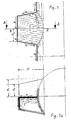
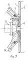
- the cylindrical shell is the gas collection chamber at an angle of 0 ° 9 penetrated by the frustoconical recess.
- the truncated cone with the depth H and with the radii R i and R 2 is formed by bending out of the tubes of the tube wall construction of the gas collecting space.
- the individual tubes of the cylindrical tube wall construction form the outer surface of the niche truncated cone such that, for example, the tube 1 a leaves the vertically downward alignment of the cylindrical tube wall construction at the level of the penetration point of the truncated cone and cylinder, at an angle turns according to the slope of the truncated cone, runs along the surface line of the truncated cone until radius R 2 is reached, forms half the circumference ⁇ ⁇ P 2 on the upper, smaller circle of the truncated cone, then turns again into the surface line, which runs down to the bottom Penetration point in order to then merge into the original, vertical, downward alignment of the cylindrical tube wall construction.
- the tube 1a forms part of the outer shape of the conical niche.
- the tubes 1b-1i also run in a corresponding manner and form the surface of the jacket of one niche half, while the other half is formed by the same number of tubes, not shown in FIGS. 1 and 1a.
- the casing pipes of the cylindrical pipe wall construction and that of the truncated cone-shaped niche thus represent a uniform pipe system.
- Each individual pipe forms part of the niche, all pipes form a tight fit, the entire niche is tightly welded.
- the two halves of the niche are also welded together gas-tight.
- the depth of the niche can also be extended by welding in webs, not shown, between the individual tubes to a certain extent, due to thermal reasons, as well as by using separately fed tube windings, which are also not shown.
- the niche constructed from pipe loops, as described above, is covered by a cover plate, not shown in FIGS. 1 and 1a, on which the burner units for gasifying the fuel are attached.
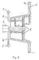
- Fig. 2 shows a proposal for three different uses.
- the niche is formed from a multiplicity of tubes, of which only the tube 1a is indicated here. 2 with a layer of refractory material applied to protect the pipes is designated.
- the burner 3 protrudes into the recess, which is closed off by a vertical tube wall 4 which is likewise protected by applied refractory material.
- the water required for cooling the pipe wall 4 flows through collector pipes 5 via elbows 6 to and from.
- the niche insert with the pipe wall 4 and the protection made of refractory material, the burner 3 and the collector pipes 5 detachable from the water supply and disposal are removed and replaced by a larger niche insert with a likewise protected pipe wall, the niche, for example at a distance x from the previous pipe wall 4. If, on the other hand, the niche is to be enlarged, a correspondingly smaller niche insert is selected, which e.g. at a distance Y from the previous position of the tube wall 4.
- any advantageous niche size can be selected depending on the operating parameters by changing the depth H of the niche (FIG. 1).
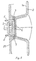
- the niche with the reaction space for the gasification is closed off by a cover plate 20 to the outside space, where ambient pressure prevails in comparison to the increased gasification pressure.
- the cover plate shown in FIGS. 1 and 2 not shown for simplification forms a detachable unit with the burner 3 pushed into it. Since it is not itself cooled, it has, as heat protection, the tube wall 4 with protection made of refractory material, which at the same time forms the niche closure according to the explanations for FIG. 2.
- the pipe 5 cooling water flows in and out through the pipes 5.
- a sealing system 7 is provided on the cover plate, which consists of two welded-on, concentric rings, the space between which is filled with heat-resistant, elastic sealing compound. Gas tightness is achieved by pressing the plate with the burner 3 against the pipe 1a, which is pressed into the sealing compound. If the reaction space for the gasification is to be changed, the procedure according to the proposal in FIG. 2 can be followed.
- Determining the construction of the niche jacket according to FIGS. 1-3 can be disadvantageous for the reasons given when building a gasification plant for later operation.
- the invention therefore also provides for a departure from the niche shown in FIGS. 1-3 and integrated into the tube wall construction of the gas collecting space. It is based on a cylindrical tube wall construction, in which only passage openings are provided, in which niches of different geometric shapes can be used. In this case, not only is the depth of the niche variable, as in the embodiment according to FIGS. 1-3, but also, if necessary, its width and the angle of inclination of the niche shell.
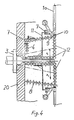
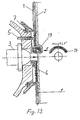
- FIG. 4 A niche construction of the type described above with variable width and variable inclination angle is shown in FIG. 4.
- the tubular body 12 forms the smallest niche construction that can be carried out. Between this shape of the tubular body 12 and the shape indicated by 8, a large number of widths and angles of inclination are structurally possible if the niche width is changed in the direction of the arrows x. In the case of the different constructions used in each case, the horizontal part of the tubular body 12 migrates towards the tubular body 8 in the direction of the arrow.
- the actual gasification niche is formed by the frustoconical tubular body 8, which can be shaped spirally or by parallel tubes.
- the tube body 8 rests with a ring 9 welded on tightly against the stop 10 which is also insoluble in the passage opening.
- the tubular body 8 is guided through a ring welded to it from an angle iron 11.
- the free leg of the angle iron 11 engages in the sealing system 7, which is fastened to the cylindrical tube wall construction in the region of the passage opening and thus creates a gas-tight seal.
- Another sealing system 7 is in turn provided on the cover plate 20 with the burner 3.
- the connections for the cooling water inlet and outlet are not shown in FIG. 4, but essentially correspond to those according to FIG. 2.
- FIGS. 5-7 show one of the possible embodiments.
- the tubes 1a-1j run vertically down the upper half of the tube wall construction. At the point where they have reached the corresponding point on the circumference of the passage point, they are from the vertically downward escape line at an angle of max. 9 0 ° bent away from the gas side towards the burner. This happens both in the upper half I and in the lower half II of the passage point. If the free legs of the bent pipe angles reach the length C according to FIGS. 6 and 7, they are deflected in the direction of the circumference of the passage point and run parallel to the passage point at a distance C over half the circumference, in order to - as shown in FIG. 5 - at the lower half II in the reverse order of the redirections into the pipe wall construction.
- the tubes la-1 of the tube wall construction form the tube collar in FIGS. 6 and 7, while the tubes 1i and 1j pass through without deflections in the vertically downward alignment line of the cylindrical tube wall construction.
- Sealing systems 7 can be arranged on the pipe collar 1 a - 1, by means of which the niches to be used with the cover plate and the burner — not shown here — can be adjusted gas-tight, as described above. As indicated in Fig. 5 by the hatching between the tubes, the Entire cylindrical tube wall construction welded gas-tight.
- a tube wall construction designed in accordance with the above description with one or more passage points enables the use of variable niches up to the complete closure of the passage point.
- FIGS. 8 and 9 Another embodiment of the passage point is shown in FIGS. 8 and 9.
- FIG. 8 is the view of the passage point from the burner onto the pipe wall construction and
- FIG. 9 is a section along the line C-C according to FIG. 8.
- the pipes la-1 open into a collector 14 instead of forming a pipe collar.
- the collector tube 14 is gem.
- Fig. 8 led past the passage point and feeds the lower half of the pipes at this point of the pipe wall construction.
- sealing systems 7 can be provided, with the aid of which the gas tightness with respect to the gasification interior is ensured.
- This embodiment takes up little space, is structurally simpler and less complex to carry out than that shown in FIGS. 5-7, and is therefore particularly advantageous.
- a collector tube two semi-circular ones can also be provided.
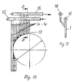
- FIG. 1o A further advantageous embodiment for a compact construction at the passage point is shown in Fig. 1o.
- inlet pipes 15 and outlet pipes 16 From the inlet pipe 15, the cooling water flows into pipes 1a-1e.
- the cooling water flow at the lower end of the tubes 1 a - 1 e is deflected from the downward to the upward flow direction by a corresponding number of angle fittings 17, which are in alignment with the passage point on the circumference of the cylindrical tube wall construction, so that the water flow flows through the drain pipe 16.
- FIG. 11 shows in section along the line D-D according to FIG. 1o the inlet and outlet pipes 15 and 16 arranged offset with respect to one another.
- the passage point must be closed by a component which corresponds to the design of the pipe wall construction and which also contains the burner.
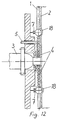
- Fig. 12 shows such a closure for a passage point in the cylindrical tube wall construction, in which the vertically downward directed tubes 1 open into an annular collector 18 forming the circumference of the passage point and integrated into the tube wall construction, the cross section of which is designed such that one for a sufficient Cooling required flow rate of the cooling water is reached.
- the sealing system 7 is attached to this ring collector.
Landscapes
- Chemical & Material Sciences (AREA)
- Engineering & Computer Science (AREA)
- Combustion & Propulsion (AREA)
- Oil, Petroleum & Natural Gas (AREA)
- Organic Chemistry (AREA)
- Gasification And Melting Of Waste (AREA)
- Feeding And Controlling Fuel (AREA)
Applications Claiming Priority (2)
| Application Number | Priority Date | Filing Date | Title |
|---|---|---|---|
| DE19863613508 DE3613508A1 (de) | 1986-04-22 | 1986-04-22 | Einrichtung zur vergasung feinzerteilter, insbesondere fester brennstoffe unter erhoehtem druck |
| DE3613508 | 1986-04-22 |
Publications (3)
| Publication Number | Publication Date |
|---|---|
| EP0242504A2 EP0242504A2 (de) | 1987-10-28 |
| EP0242504A3 EP0242504A3 (en) | 1988-05-11 |
| EP0242504B1 true EP0242504B1 (de) | 1990-04-18 |
Family
ID=6299209
Family Applications (1)
| Application Number | Title | Priority Date | Filing Date |
|---|---|---|---|
| EP87100840A Expired - Lifetime EP0242504B1 (de) | 1986-04-22 | 1987-01-22 | Einrichtung zur Vergasung feinzerteilter, insbesondere fester Brennstoffe unter erhöhtem Druck |
Country Status (7)
| Country | Link |
|---|---|
| US (1) | US4818252A (es) |
| EP (1) | EP0242504B1 (es) |
| DE (2) | DE3613508A1 (es) |
| ES (1) | ES2014436B3 (es) |
| GR (1) | GR3000814T3 (es) |
| TR (1) | TR22809A (es) |
| ZA (1) | ZA87837B (es) |
Families Citing this family (15)
| Publication number | Priority date | Publication date | Assignee | Title |
|---|---|---|---|---|
| DE4017219A1 (de) * | 1990-05-29 | 1991-12-05 | Babcock Werke Ag | Vorrichtung zur vergasung von kohlenstoffhaltigen materialien |
| US9051522B2 (en) * | 2006-12-01 | 2015-06-09 | Shell Oil Company | Gasification reactor |
| WO2008087133A1 (en) * | 2007-01-17 | 2008-07-24 | Shell Internationale Research Maatschappij B.V. | Gasification reactor |
| AU2008225747B2 (en) * | 2007-03-15 | 2011-06-02 | Air Products And Chemicals, Inc. | Gasification reactor vessel with inner multi-pipe wall and several burners |
| CN201205497Y (zh) * | 2007-03-30 | 2009-03-11 | 国际壳牌研究有限公司 | 气化反应器 |
| DE102008034112A1 (de) * | 2008-07-21 | 2010-01-28 | Uhde Gmbh | Schlackerinne an Brennern zum Schutz vor herabfließender Schlacke |
| US8960651B2 (en) * | 2008-12-04 | 2015-02-24 | Shell Oil Company | Vessel for cooling syngas |
| US8475546B2 (en) * | 2008-12-04 | 2013-07-02 | Shell Oil Company | Reactor for preparing syngas |
| CN102985195B (zh) * | 2010-06-08 | 2016-01-27 | 三照普燃料公司 | 用于超高热通量化学反应器的各种方法和装置 |
| GB201012461D0 (en) * | 2010-07-26 | 2010-09-08 | Doosan Power Systems Ltd | Furnace tube arrangment for a steam generator |
| US10035960B2 (en) | 2010-09-07 | 2018-07-31 | Saudi Arabian Oil Company | Process for oxidative desulfurization and sulfone management by gasification |
| US9574142B2 (en) | 2010-09-07 | 2017-02-21 | Saudi Arabian Oil Company | Process for oxidative desulfurization and sulfone management by gasification |
| DE102010047145A1 (de) * | 2010-09-30 | 2012-04-05 | Alstom Technology Ltd. | Wandausbiegung im Bereich einer im wesentlich rechteckförmigen Brenneröffnung |
| US9234146B2 (en) | 2011-07-27 | 2016-01-12 | Saudi Arabian Oil Company | Process for the gasification of heavy residual oil with particulate coke from a delayed coking unit |
| WO2017063981A1 (en) | 2015-10-12 | 2017-04-20 | Shell Internationale Research Maatschappij B.V. | Cooling device for a burner of a gasification reactor |
Family Cites Families (10)
| Publication number | Priority date | Publication date | Assignee | Title |
|---|---|---|---|---|
| DE968423C (de) * | 1948-12-07 | 1958-02-13 | Koppers Co Inc | Verfahren und Vorrichtung zum Erzeugen von feinkoernigem Koks aus bituminoesen Brennstoffen |
| DE1076868B (de) * | 1958-04-30 | 1960-03-03 | Koppers Gmbh Heinrich | Einrichtung zur Brenngaserzeugung durch Vergasung feinverteilter Brennstoffe |
| US3233597A (en) * | 1963-12-30 | 1966-02-08 | Combustion Eng | Apparatus for forming openings in furnace walls |
| DE2038445C3 (de) * | 1970-08-01 | 1978-06-15 | Krupp-Koppers Gmbh, 4300 Essen | Gasgenerator für feinkörnige Kohle-Brennstoffe |
| US3712602A (en) * | 1971-02-22 | 1973-01-23 | Steel Corp | Blast furnace tuyere and method of operating same |
| DE2425962C3 (de) * | 1974-05-30 | 1979-04-05 | Shell Internationale Research Maatschappij B.V., Den Haag (Niederlande) | Gasgenerator für die Vergasung feinzerteilter Brennstoffe |
| DE2504060A1 (de) * | 1975-01-31 | 1976-08-05 | Otto & Co Gmbh Dr C | Unter druck arbeitender schlackenbadgenerator |
| US4394849A (en) * | 1981-06-22 | 1983-07-26 | Foster Wheeler Energy Corporation | Vapor generator having drainable tube bends around burner openings extending through furnace boundary walls formed in part by angularly extending fluid flow tubes |
| EP0133453B1 (de) * | 1983-08-05 | 1988-07-27 | GebràDer Sulzer Aktiengesellschaft | Wärmeübertrager, insbesondere Dampferzeuger |
| CN1010028B (zh) * | 1985-05-29 | 1990-10-17 | 国际壳牌研究有限公司 | 褐煤气化器 |
-
1986
- 1986-04-22 DE DE19863613508 patent/DE3613508A1/de not_active Withdrawn
-
1987
- 1987-01-22 EP EP87100840A patent/EP0242504B1/de not_active Expired - Lifetime
- 1987-01-22 DE DE8787100840T patent/DE3762351D1/de not_active Expired - Fee Related
- 1987-01-22 ES ES87100840T patent/ES2014436B3/es not_active Expired - Lifetime
- 1987-02-05 ZA ZA870837A patent/ZA87837B/xx unknown
- 1987-03-23 US US07/029,535 patent/US4818252A/en not_active Expired - Fee Related
- 1987-04-15 TR TR15185A patent/TR22809A/xx unknown
-
1990
- 1990-07-13 GR GR90400468T patent/GR3000814T3/el unknown
Also Published As
| Publication number | Publication date |
|---|---|
| ES2014436B3 (es) | 1990-07-16 |
| US4818252A (en) | 1989-04-04 |
| DE3762351D1 (de) | 1990-05-23 |
| EP0242504A2 (de) | 1987-10-28 |
| TR22809A (tr) | 1988-08-09 |
| EP0242504A3 (en) | 1988-05-11 |
| DE3613508A1 (de) | 1987-10-29 |
| GR3000814T3 (en) | 1991-11-15 |
| ZA87837B (en) | 1987-07-30 |
Similar Documents
| Publication | Publication Date | Title |
|---|---|---|
| EP0242504B1 (de) | Einrichtung zur Vergasung feinzerteilter, insbesondere fester Brennstoffe unter erhöhtem Druck | |
| EP0366606B1 (de) | Heissgaskühlanlage zu einer Kohlevergasungsanlage | |
| DE2517693C2 (de) | Als Längsgegenstromapparat ausgebildeter Wärmeaustauscher | |
| DE3009851C2 (de) | Reaktorbehälter, insbesondere zur Vergasung fossiler Brennstoffe | |
| DE3119905C2 (es) | ||
| DE3043853C2 (de) | Heißgaskühler mit einem Druckbehälter | |
| EP0007977A1 (de) | Verfahren zum Brennen von stückigem Brenngut sowie Ringschachtofen zu seiner Durchführung | |
| DE3009850A1 (de) | Reaktorbehaelter | |
| DE3605811C2 (es) | ||
| DE4212177C2 (de) | Verbrennungsanlage | |
| DE3208421C2 (es) | ||
| EP0128463B1 (de) | Raumheizgerät für Kleinräume | |
| DE2110197A1 (de) | Ofen zum Erhitzen von Flüssigkeiten oder Gasen | |
| CH686741A5 (de) | Dampferzeuger. | |
| DE2224899A1 (de) | Wärmetauscher | |
| DE3322464C2 (es) | ||
| DE2814155A1 (de) | Waermetauscher fuer verbrennungsanlagen | |
| DE2441706A1 (de) | Heizkessel mit gusseisernen gerippten rohren | |
| DE3012596C2 (es) | ||
| DE4221130C2 (de) | Wasserrohr-Dampferzeuger mit vertikal angeordneten Fieldrohren | |
| EP0630397B1 (de) | Verfahren zum kühlen eines staubbeladenen rohgases aus der vergasung eines festen kohlenstoffhaltigen brennstoffes | |
| DE3153042C2 (de) | Vorrichtung zur Kühlung der Wandung eines Schachtofens, insbesondere Hochofens | |
| DE2751942C2 (de) | Gaserzeuger mit Schlackenaustrag in eine Löschkammer | |
| DE3878673T2 (de) | Schornstein mit kondensatableitung. | |
| DE3921670C2 (es) |
Legal Events
| Date | Code | Title | Description |
|---|---|---|---|
| PUAI | Public reference made under article 153(3) epc to a published international application that has entered the european phase |
Free format text: ORIGINAL CODE: 0009012 |
|
| AK | Designated contracting states |
Kind code of ref document: A2 Designated state(s): DE ES GR |
|
| PUAL | Search report despatched |
Free format text: ORIGINAL CODE: 0009013 |
|
| AK | Designated contracting states |
Kind code of ref document: A3 Designated state(s): DE ES GR |
|
| 17P | Request for examination filed |
Effective date: 19880426 |
|
| 17Q | First examination report despatched |
Effective date: 19890810 |
|
| GRAA | (expected) grant |
Free format text: ORIGINAL CODE: 0009210 |
|
| AK | Designated contracting states |
Kind code of ref document: B1 Designated state(s): DE ES GR |
|
| REF | Corresponds to: |
Ref document number: 3762351 Country of ref document: DE Date of ref document: 19900523 |
|
| REG | Reference to a national code |
Ref country code: GR Ref legal event code: FG4A Free format text: 3000814 |
|
| PLBE | No opposition filed within time limit |
Free format text: ORIGINAL CODE: 0009261 |
|
| STAA | Information on the status of an ep patent application or granted ep patent |
Free format text: STATUS: NO OPPOSITION FILED WITHIN TIME LIMIT |
|
| 26N | No opposition filed | ||
| PGFP | Annual fee paid to national office [announced via postgrant information from national office to epo] |
Ref country code: DE Payment date: 19961217 Year of fee payment: 11 |
|
| PGFP | Annual fee paid to national office [announced via postgrant information from national office to epo] |
Ref country code: GR Payment date: 19961223 Year of fee payment: 11 |
|
| PGFP | Annual fee paid to national office [announced via postgrant information from national office to epo] |
Ref country code: ES Payment date: 19970129 Year of fee payment: 11 |
|
| PG25 | Lapsed in a contracting state [announced via postgrant information from national office to epo] |
Ref country code: ES Free format text: LAPSE BECAUSE OF NON-PAYMENT OF DUE FEES Effective date: 19980123 |
|
| PG25 | Lapsed in a contracting state [announced via postgrant information from national office to epo] |
Ref country code: GR Free format text: LAPSE BECAUSE OF NON-PAYMENT OF DUE FEES Effective date: 19980131 |
|
| PG25 | Lapsed in a contracting state [announced via postgrant information from national office to epo] |
Ref country code: DE Free format text: LAPSE BECAUSE OF NON-PAYMENT OF DUE FEES Effective date: 19981001 |
|
| REG | Reference to a national code |
Ref country code: ES Ref legal event code: FD2A Effective date: 20000503 |