EP0241694A1 - Equilibreur automatique pour la force de pression d'un outil d'une machine de nettoyage de surface - Google Patents
Equilibreur automatique pour la force de pression d'un outil d'une machine de nettoyage de surface Download PDFInfo
- Publication number
- EP0241694A1 EP0241694A1 EP87103135A EP87103135A EP0241694A1 EP 0241694 A1 EP0241694 A1 EP 0241694A1 EP 87103135 A EP87103135 A EP 87103135A EP 87103135 A EP87103135 A EP 87103135A EP 0241694 A1 EP0241694 A1 EP 0241694A1
- Authority
- EP
- European Patent Office
- Prior art keywords
- tool
- force
- signal
- load
- comparison
- Prior art date
- Legal status (The legal status is an assumption and is not a legal conclusion. Google has not performed a legal analysis and makes no representation as to the accuracy of the status listed.)
- Granted
Links
Images


Classifications
-
- A—HUMAN NECESSITIES
- A47—FURNITURE; DOMESTIC ARTICLES OR APPLIANCES; COFFEE MILLS; SPICE MILLS; SUCTION CLEANERS IN GENERAL
- A47L—DOMESTIC WASHING OR CLEANING; SUCTION CLEANERS IN GENERAL
- A47L9/00—Details or accessories of suction cleaners, e.g. mechanical means for controlling the suction or for effecting pulsating action; Storing devices specially adapted to suction cleaners or parts thereof; Carrying-vehicles specially adapted for suction cleaners
- A47L9/28—Installation of the electric equipment, e.g. adaptation or attachment to the suction cleaner; Controlling suction cleaners by electric means
- A47L9/2894—Details related to signal transmission in suction cleaners
-
- A—HUMAN NECESSITIES
- A47—FURNITURE; DOMESTIC ARTICLES OR APPLIANCES; COFFEE MILLS; SPICE MILLS; SUCTION CLEANERS IN GENERAL
- A47L—DOMESTIC WASHING OR CLEANING; SUCTION CLEANERS IN GENERAL
- A47L11/00—Machines for cleaning floors, carpets, furniture, walls, or wall coverings
- A47L11/02—Floor surfacing or polishing machines
- A47L11/20—Floor surfacing or polishing machines combined with vacuum cleaning devices
-
- A—HUMAN NECESSITIES
- A47—FURNITURE; DOMESTIC ARTICLES OR APPLIANCES; COFFEE MILLS; SPICE MILLS; SUCTION CLEANERS IN GENERAL
- A47L—DOMESTIC WASHING OR CLEANING; SUCTION CLEANERS IN GENERAL
- A47L11/00—Machines for cleaning floors, carpets, furniture, walls, or wall coverings
- A47L11/40—Parts or details of machines not provided for in groups A47L11/02 - A47L11/38, or not restricted to one of these groups, e.g. handles, arrangements of switches, skirts, buffers, levers
- A47L11/4011—Regulation of the cleaning machine by electric means; Control systems and remote control systems therefor
-
- A—HUMAN NECESSITIES
- A47—FURNITURE; DOMESTIC ARTICLES OR APPLIANCES; COFFEE MILLS; SPICE MILLS; SUCTION CLEANERS IN GENERAL
- A47L—DOMESTIC WASHING OR CLEANING; SUCTION CLEANERS IN GENERAL
- A47L11/00—Machines for cleaning floors, carpets, furniture, walls, or wall coverings
- A47L11/40—Parts or details of machines not provided for in groups A47L11/02 - A47L11/38, or not restricted to one of these groups, e.g. handles, arrangements of switches, skirts, buffers, levers
- A47L11/4052—Movement of the tools or the like perpendicular to the cleaning surface
- A47L11/4058—Movement of the tools or the like perpendicular to the cleaning surface for adjusting the height of the tool
-
- A—HUMAN NECESSITIES
- A47—FURNITURE; DOMESTIC ARTICLES OR APPLIANCES; COFFEE MILLS; SPICE MILLS; SUCTION CLEANERS IN GENERAL
- A47L—DOMESTIC WASHING OR CLEANING; SUCTION CLEANERS IN GENERAL
- A47L9/00—Details or accessories of suction cleaners, e.g. mechanical means for controlling the suction or for effecting pulsating action; Storing devices specially adapted to suction cleaners or parts thereof; Carrying-vehicles specially adapted for suction cleaners
- A47L9/28—Installation of the electric equipment, e.g. adaptation or attachment to the suction cleaner; Controlling suction cleaners by electric means
- A47L9/2805—Parameters or conditions being sensed
- A47L9/2831—Motor parameters, e.g. motor load or speed
-
- A—HUMAN NECESSITIES
- A47—FURNITURE; DOMESTIC ARTICLES OR APPLIANCES; COFFEE MILLS; SPICE MILLS; SUCTION CLEANERS IN GENERAL
- A47L—DOMESTIC WASHING OR CLEANING; SUCTION CLEANERS IN GENERAL
- A47L9/00—Details or accessories of suction cleaners, e.g. mechanical means for controlling the suction or for effecting pulsating action; Storing devices specially adapted to suction cleaners or parts thereof; Carrying-vehicles specially adapted for suction cleaners
- A47L9/28—Installation of the electric equipment, e.g. adaptation or attachment to the suction cleaner; Controlling suction cleaners by electric means
- A47L9/2836—Installation of the electric equipment, e.g. adaptation or attachment to the suction cleaner; Controlling suction cleaners by electric means characterised by the parts which are controlled
- A47L9/2847—Surface treating elements
-
- A—HUMAN NECESSITIES
- A47—FURNITURE; DOMESTIC ARTICLES OR APPLIANCES; COFFEE MILLS; SPICE MILLS; SUCTION CLEANERS IN GENERAL
- A47L—DOMESTIC WASHING OR CLEANING; SUCTION CLEANERS IN GENERAL
- A47L9/00—Details or accessories of suction cleaners, e.g. mechanical means for controlling the suction or for effecting pulsating action; Storing devices specially adapted to suction cleaners or parts thereof; Carrying-vehicles specially adapted for suction cleaners
- A47L9/28—Installation of the electric equipment, e.g. adaptation or attachment to the suction cleaner; Controlling suction cleaners by electric means
- A47L9/2857—User input or output elements for control, e.g. buttons, switches or displays
-
- A—HUMAN NECESSITIES
- A47—FURNITURE; DOMESTIC ARTICLES OR APPLIANCES; COFFEE MILLS; SPICE MILLS; SUCTION CLEANERS IN GENERAL
- A47L—DOMESTIC WASHING OR CLEANING; SUCTION CLEANERS IN GENERAL
- A47L9/00—Details or accessories of suction cleaners, e.g. mechanical means for controlling the suction or for effecting pulsating action; Storing devices specially adapted to suction cleaners or parts thereof; Carrying-vehicles specially adapted for suction cleaners
- A47L9/28—Installation of the electric equipment, e.g. adaptation or attachment to the suction cleaner; Controlling suction cleaners by electric means
- A47L9/2889—Safety or protection devices or systems, e.g. for prevention of motor over-heating or for protection of the user
-
- E—FIXED CONSTRUCTIONS
- E01—CONSTRUCTION OF ROADS, RAILWAYS, OR BRIDGES
- E01H—STREET CLEANING; CLEANING OF PERMANENT WAYS; CLEANING BEACHES; DISPERSING OR PREVENTING FOG IN GENERAL CLEANING STREET OR RAILWAY FURNITURE OR TUNNEL WALLS
- E01H1/00—Removing undesirable matter from roads or like surfaces, with or without moistening of the surface
- E01H1/02—Brushing apparatus, e.g. with auxiliary instruments for mechanically loosening dirt
- E01H1/05—Brushing apparatus, e.g. with auxiliary instruments for mechanically loosening dirt with driven brushes
- E01H1/056—Brushing apparatus, e.g. with auxiliary instruments for mechanically loosening dirt with driven brushes having horizontal axes
Definitions
- the present invention relates to an automatic tool force compensator for a surface maintenance machine and has particular application to an electric control which raises and Lowers the surface maintenance tools in response to changes in the elevation or condition of the surface being maintained or changes in the tool due to wear.
- a primary purpose is an automatic tool force compensator used to maintain a predetermined force on a surface being maintained which compensates for variations in elevation of the surface.
- Another purpose is an automatic tool force compensator that prevents excessive force from being applied to a surface by a maintainance tool, thereby reducing damage and wear on the tool and extending its Life.
- Another purpose is an automatic tool force compensator used to maintain a predetermined force on a surface being maintained which compensates for changes in the tool due to wear.
- Another purpose is an automatic tool force compensator which senses changes in condition of the surface being maintained by monitoring the Load on the tool drive motors and adjusts the applied tool force on the surface to maintain the motor Load within set Limits.
- Another purpose is an automatic tool force compensator which utilizes a Load ceLL to measure force applied by a maintenance tool on a surface being maintained and causes it to be varied as necessary to maintain it within desired limits.
- Another purpose is an automatic tool force compensator which utilizes an actuator to raise and Lower a surface maintenance tooL and thereby vary the force which the tool applies on the surface being maintained to keep the force within set Limits.
- Another purpose is an automatic tooL force compensator which prevents opposite direction tooL movement signals from being simultaneously applied to the tooL actuator.
- Another purpose is an automatic tool force compensator of the type described which is simply constructed and reLiabLy operable.
- the present invention is directed to surface maintenance machines and more specifically to an automatic tool force compensator for such machines.
- the invention wiLL be specifically described in connection with a floor scrubbing machine, however, it should be recognized that the invention has substantially wider application.
- the compensating means disclosed herein is also applicable to other brush type machines such as sweepers, as well as to other types of floor tools or surface maintenance tools such as pads for poLishing, cleaning or burnishing; sanding drums or belts for removing worn floor coatings; and scraping tools for removing packed soiLage or worn coatings.
- the machine wiLL be described in connection with treating a fLoor, other surfaces such as sidewaLks, parking Lots and streets could also be treated by machines utilizing the present invention.
- the tool force compensating means disclosed is directed to controlling the force applied by the tool to the surface being treated whether it be a brush to a floor or some other type of tool to some other type of surface. Such control is required in order to attain the maximum efficiency in treating the surface.
- SpecificaLLy in the case of a brush, it is desired to maintain, to the extent practical, a certain pattern of brush contact with the floor so that the operator is aware of the degree to which the brush is applying its rotating motion to the floor.
- the applied pattern is a function of the applied force and the stiffness of the brush bristles. The bristles become stiffer as they wear shorter, so the pattern wiLL become narrower as the brush wears even if constant force is applied at aLL times.
- a force wear compensator is a more accurate description of the invention than a pattern controL, although cLearLy the pattern of the application tool is important in terms of operator control.
- the force that is sensed is actuaLLy the weight of the tool. This is particuLarLy true with a scrubbing brush. However, in other applications it may be required that a downward force, greater than the weight of the tool, be exerted on the underlying surface. This would particuLarLy be the case in a sander or scarifying tool.
- the invention not only provides a means for automatically compensating for tooL wear, but it also compensates for varying elevations in the surface being treated.
- Prior art machines with fixed tools have very LittLe capacity to conform to fLoor variations.
- a sweeper or scrubber using a fixed brush mounting has only the resilience of the brush bristLes where they are bent by contact with the floor to provide a measure of floor conformance.
- Other tooLs, such as scarifiers, when rigidly mounted may have no abiLity at aLL to conform to fLoor irreguLarities.
- undulations and disparities are common in floors and other surfaces and a machine in which the tool can move up and down and foLLow such variations is far more efficient and provides a more uniform maintenance function than a tool which does not have this ability.
- the drive motors for the brushes discLosed herein are electric.
- the invention is equally applicable to hydraulic motors which are common in floor sweepers. OverLoad in an electric motor is sensed as excessive current, whereas, overload in a hydraulic motor wiLL create excessive pressure differential across the motor. Either type of Load can be sensed and a signal provided to indicate that in fact there is an overload on the motor.
- Such motor overload can be caused not only by excessive force applied to the surface being treated, but also by changes in floor conditions. For example, a scrubber might hit a patch of sticky material such as molasses or a section of rough concrete in an otherwise smooth floor. A sweeper in a parking Lot might hit a stretch of deep sand.
- the invention as described herein provides means for sensing such an overloaded condition on the tool drive motors as well as for sensing tool wear.
- a certain portion of the weight of the brushes and the supporting mechanism, including the brush drive motors, is actuaLLy supported on the floor.
- the proper brush pattern or area of contact of the brushes on the floor is maintained by sensing the weight of the brushes and supporting apparatus which is carried by the floor and when that weight changes, the position of the brushes is adjusted to restore the floor supported weight to its original value.
- the position of the brushes is adjusted by the weight of the brushes being carried by the floor so as to maintain a pre-determined area of contact by the brushes on the floor, which in turn insures that the brushes are being properly utilized to scrub or sweep the fLoor.
- a vehicle is indicated generaLLy at 10 and may have support wheels 12 and 14.
- the vehicle may be of the type known as an automatic guided vehicle in that it foLLows a cabLe buried in the floor, but, as indicated above, the invention should not be Limited to any particular type of vehicLe.
- the vehicle is a forklift truck and the scrubbing apparatus is mounted thereon and indicated generaLLy at 16.
- the scrubbing apparatus includes a solution tank 18, a recovery tank 20 and a scrub head assembly 22.
- the solution is applied to the floor from tank 18 and after the brushes in the scrub head have scrubbed the fLoor, the solution is sucked up by a vacuum hose 24 whose nozzle 26 is positioned in a vacuum squeegee assembly 28.
- the solution from the squeegee and the vacuum hose is passed to the recovery tank.
- the scrub head assembLy which is illustrated in more detail in Figures 2 and 3, includes a pair of counterrotating brushes 30 and 32 which are driven by a pair of brush drive motors 34 and 36.
- An enclosed chain drive is indicated at 38 and it reduces motor speed down to a more appropriate brush speed.
- the scrub head assembly 22 is supported by spring-Loaded Linkage 40, threaded rod 42, Load ceLL 44 and threaded rod 43, which is pivotally connected at 48 to beLL crank 50, the opposite end of which is pivotaLLy connected to outwardly extending rod 52 of an electric actuator 54.
- Linkage 40 includes-a coLLar 41 connected to a sleeve 45 which together enclose a spring 46. It is in a free state between pLates 47 and 49 which slide freely on rod 51. This is attached to the scrub head by clevis 53 and pin 55. Either a push or a puLL by actuator 54 wiLL compress spring 46 and cause it to exert a downward or upward force on the scrub head. This arrangement also aLLows the scrub head to move up and down if it encounters irregularities in the floor because spring 46 wiLL yield resiLientLy.
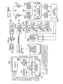
- FIG 4 a block diagram of the control circuit, user "up” and “down” switches are indicated at 60 and 62 and are avaiLabLe for the operator to initiaLLy set the brush application force or the area of contact between the brush and the floor.
- Each of the switches is connected to a four-bit up-down counter 64 which in turn is connected to a ten output sequencer 66.
- Sequencer 66 is in circuit with a display 68 which provides an indication of the brush force determined by the operator's use of the up-down switches.
- the operator by operating the switches in a conventional manner, may change the set brush force and this wiLL be shown in the display. ALthough ten positions of the brush are indicated, the invention should not be so Limited and the desired brush force and the degree of adjustment thereof wiLL depend upon the size of the machine and the particular type of maintenance action -- scrubbing, sweeping, burnishing, polishing or whatever.
- sequencer 66 which wiLL be a digital representation of one of ten possible brush force applications, is connected to a variable voltage reference selector 70 which provides an anaLo g output voltage representative of the particular brush force seLected.
- the output fror selector 70 is connected to an amplifier 72 which then provides a reference voltage LeveL to a window comparator 74.
- a power supply is indicated at 76 and is connected to Load ceLL 44, with the output of the Load ceLL being connected to an amplifier 78.
- AmpLifier 78 provides an analog voLtage representative of the force applied through the Load ceLL and this analog voltage wiLL be compared with the reference voltage as set by the operator with up-down switches 60 and 62.
- Window comparator 74 wiLL provide a signaL to either raise or Lower the scrub head assembly, depending upon whether or not the actual brush force is above or below the window determeined by the reference voltage.
- the outputs of the comparator for up and down movement are indicated on Lines 80 and 82.
- the present invention provides a method for sensing the current in the brush drive motors and controLLing it within preset Limits.
- the drive motors for the brushes are indicated at 84 and 86 and each drive motor has a current sensor indicated at 88 and 90, respectiveLy, associated therewith.
- the two current sensors are connected to window comparators 92, with the window of current being compared having been selected by a high current Limit resistor 94 and a Low current Limit resistor 96.
- the current drawn by each motor is compared with the reference high and Low current LeveLs as determined by the above-designated resistors and if the current drawn by either motor is outside of the window, there wiLL be a signaL from comparators 92 to ten-second deLay circuits 98.
- the delay circuits prevent transient overloads from causing a false indication that motor current is outside of the set Limits.
- the outputs of delay circuits 98 are connected to a signal processor 100 which is essentiaLLy an amplifier and will provide an amplified output of the signaL resulting from the comparison of reference Load current vs. actual Load current.
- integrator 102 receives the two outputs from window comparator 74.
- Integrator 102 is connected to a current amplifier 103 which is connected to a power amplifier 105 which in turn is connected to a bidirectional actuator 107 which raises and Lowers the scrub head assembly.
- integrator 102 receives a signal from comparator 74 to either raise or Lower the scrub head assembly based on a comparison of the force of the brushes being applied to the floor or a signal to either raise or Lower the scrub head assembly based on a comparison of brush motor Load current vs. a reference current.
- the output from signal processor 100 is also connected to an OR gate 106 which has its output connected to a ten-second timer 108.
- Timer 108 is connected to integrator 102.
- OR gate 106 and timer 108 provides a signal to the integrator which prevents the integrator from functioning in response to the signal from comparator 74 for a period of ten seconds after the integrator has received a command from signal processor 100 to raise or Lower the brushes. Without such a Lockout, the signals from the two comparators could direct the scrub head assenbLy actuator to move the brushes in contrary directions. If an overload is sensed on the brush motors, the brushes wiLL be raised and timer i08 wiLL not permit a signal from window comparator 74 to Lower the brushes for a period of ten seconds.
- Low motor drive current can, however, be an indication that the brushes are not adequateLy treating a fLoor surface.
- the sensing of motor current wiLL supplement the signaL from comparator 74 indicating that the brushes shouLd be Lowered.
Priority Applications (1)
| Application Number | Priority Date | Filing Date | Title |
|---|---|---|---|
| AT87103135T ATE50133T1 (de) | 1986-03-14 | 1987-03-05 | Automatische ausgleichvorrichtung fuer den werkzeug-anpressdruck einer reinigungsmaschine fuer oberflaechen. |
Applications Claiming Priority (2)
| Application Number | Priority Date | Filing Date | Title |
|---|---|---|---|
| US839877 | 1986-03-14 | ||
| US06/839,877 US4679271A (en) | 1986-03-14 | 1986-03-14 | Automatic tool force compensator for a surface maintenance machine |
Publications (2)
| Publication Number | Publication Date |
|---|---|
| EP0241694A1 true EP0241694A1 (fr) | 1987-10-21 |
| EP0241694B1 EP0241694B1 (fr) | 1990-02-07 |
Family
ID=25280869
Family Applications (1)
| Application Number | Title | Priority Date | Filing Date |
|---|---|---|---|
| EP87103135A Expired - Lifetime EP0241694B1 (fr) | 1986-03-14 | 1987-03-05 | Equilibreur automatique pour la force de pression d'un outil d'une machine de nettoyage de surface |
Country Status (5)
| Country | Link |
|---|---|
| US (1) | US4679271A (fr) |
| EP (1) | EP0241694B1 (fr) |
| JP (1) | JPS62241664A (fr) |
| AT (1) | ATE50133T1 (fr) |
| DE (1) | DE3761609D1 (fr) |
Cited By (5)
| Publication number | Priority date | Publication date | Assignee | Title |
|---|---|---|---|---|
| GB2280597A (en) * | 1993-08-04 | 1995-02-08 | Rentokil Ltd | Gully cleaning apparatus with depth compensation |
| GB2283905A (en) * | 1993-11-17 | 1995-05-24 | Briscoe William A | Brush pressure system for floor cleaning/sweeping machine |
| GB2290021A (en) * | 1994-06-10 | 1995-12-13 | Briscoe William A | Brush pressure control system for floor cleaning machine |
| EP0843047A1 (fr) * | 1996-11-18 | 1998-05-20 | Schmidt Holding Europe GmbH | Unité de balayage pour le montage sur un véhicule ou une remorque |
| EP0887468A3 (fr) * | 1997-06-25 | 2000-03-15 | Nilfisk Advance A/S | Balayeuse à moteur |
Families Citing this family (40)
| Publication number | Priority date | Publication date | Assignee | Title |
|---|---|---|---|---|
| US4766432A (en) * | 1986-03-14 | 1988-08-23 | Tennant Company | Telemetry system for floor maintenance machines |
| US4757566A (en) * | 1987-07-27 | 1988-07-19 | Tennant Company | Control of torque in floor maintenance tools by drive motor load |
| JP2807883B2 (ja) * | 1987-11-17 | 1998-10-08 | アマノ株式会社 | 床面艶出機 |
| DE3913390A1 (de) * | 1989-04-24 | 1990-10-25 | Stein & Co Gmbh | Einstellvorrichtung fuer bodenpflegegeraete |
| BE1004656A3 (nl) * | 1991-02-18 | 1993-01-05 | Konfoma Ind Bv | Veger. |
| US5465456A (en) * | 1992-03-24 | 1995-11-14 | National Super Service Company | Floor cleaning apparatus |
| DK0729314T3 (da) * | 1993-11-17 | 1999-06-14 | William Anthony Briscoe | Børstetryksystem |
| US5802665A (en) * | 1994-04-25 | 1998-09-08 | Widsor Industries, Inc. | Floor cleaning apparatus with two brooms |
| US5698957A (en) * | 1995-04-24 | 1997-12-16 | Advance Machine Company | Over current protective circuit with time delay for a floor cleaning machine |
| US5784742A (en) * | 1995-06-23 | 1998-07-28 | Optiva Corporation | Toothbrush with adaptive load sensor |
| US5815872A (en) * | 1997-08-08 | 1998-10-06 | Optiva Corporation | Pressure overload indicator system for power toothbrushes |
| US6042656A (en) * | 1997-10-17 | 2000-03-28 | Nilfisk-Advance, Inc. | Shutoff control methods for surface treating machines |
| USRE39581E1 (en) * | 1997-10-22 | 2007-04-24 | Alto U.S., Inc. | Brush head positioning system |
| US5943724A (en) | 1998-01-13 | 1999-08-31 | Tennant Company | Electro-hydraulic brush down force control |
| US6227957B1 (en) | 1998-05-22 | 2001-05-08 | Nilfisk-Advance, Inc. | Battery powered, riding, floor burnishing machine |
| US6450867B1 (en) | 1998-05-22 | 2002-09-17 | Nilfisk-Advance, Inc. | Battery powered, riding, floor treating machine |
| US6671925B2 (en) * | 2001-07-30 | 2004-01-06 | Tennant Company | Chemical dispenser for a hard floor surface cleaner |
| US7051399B2 (en) | 2001-07-30 | 2006-05-30 | Tennant Company | Cleaner cartridge |
| US8051861B2 (en) | 2001-07-30 | 2011-11-08 | Tennant Company | Cleaning system utilizing purified water |
| EP1396222B1 (fr) | 2002-09-07 | 2010-04-14 | Vorwerk & Co. Interholding GmbH | Dispositif de brosse aspirante pour aspirateur |
| WO2005011755A2 (fr) * | 2003-07-30 | 2005-02-10 | Tennant Company | Dispositif de sterilisation par l'ultraviolet |
| US8028365B2 (en) | 2003-09-02 | 2011-10-04 | Tennant Company | Hard and soft floor cleaning tool and machine |
| EP1810257B1 (fr) | 2004-11-12 | 2011-09-28 | Tennant Company | Communication de donnees a partir d'un appareil a recurer les parquets |
| KR101139115B1 (ko) | 2005-05-05 | 2012-04-30 | 텐난트 컴파니 | 바닥 쓸기 및 세척장치 |
| US20060272668A1 (en) * | 2005-06-02 | 2006-12-07 | The Procter & Gamble Company | Cosmetic applicator |
| US8584294B2 (en) | 2005-10-21 | 2013-11-19 | Tennant Company | Floor cleaner scrub head having a movable disc scrub member |
| CA2637956C (fr) * | 2006-01-25 | 2014-04-08 | Johnsondiversey, Inc. | Dispositif et procede de reglage de la pression entre un instrument pour nettoyer les planchers et un plancher |
| US7435160B2 (en) * | 2006-03-10 | 2008-10-14 | Marrs Iii Glenn L | Automated floor sander |
| KR20090087943A (ko) * | 2006-11-30 | 2009-08-18 | 코닝 인코포레이티드 | 워크 피스 표면의 정밀 연마 머시닝 |
| US8485201B2 (en) * | 2007-02-21 | 2013-07-16 | The Procter & Gamble Company | Cosmetic applicator with torque limiter |
| US20080196736A1 (en) * | 2007-02-21 | 2008-08-21 | The Procter & Gamble Company | Cosmetic Applicator with Torque Limiter |
| US8985883B2 (en) * | 2007-07-30 | 2015-03-24 | The Procter & Gamble Company | Control surfaces for applicator with moveable applicator head |
| US8079373B2 (en) * | 2007-09-18 | 2011-12-20 | The Proctor & Gamble Company | Applicator with helical applicator surface |
| DE102007050351A1 (de) * | 2007-10-11 | 2009-04-16 | Alfred Kärcher Gmbh & Co. Kg | Reinigungswerkzeug und Reinigungsgerät mit einem derartigen Reinigungswerkzeug |
| DE102008009221A1 (de) * | 2008-02-06 | 2009-08-13 | Alfred Kärcher Gmbh & Co. Kg | System zur Bevorratung und Abgabe von flüssigem Reinigungszusatz für Hochdruckreinigungsgerät |
| DE102009018121A1 (de) * | 2009-04-09 | 2010-10-14 | Alfred Kärcher Gmbh & Co. Kg | Verfahren zum Betreiben eines Reinigungsgerätes sowie Reinigungsgerät und Reinigungswerkzeug zur Durchführung des Verfahrens |
| DE102009033944A1 (de) | 2009-07-14 | 2011-01-20 | Alfred Kärcher Gmbh & Co. Kg | Reinigungsvorrichtung sowie Verfahren zur Kontrolle des Zugriffs auf eine Reinigungsvorrichtung |
| US8966693B2 (en) | 2009-08-05 | 2015-03-03 | Karcher N. America, Inc. | Method and apparatus for extended use of cleaning fluid in a floor cleaning machine |
| DE102010042347A1 (de) | 2010-10-12 | 2012-04-12 | Alfred Kärcher Gmbh & Co. Kg | Verfahren zum Betreiben eines Reinigungsgerätes und Reinigungsgerät zur Durchführung des Verfahrens |
| CN104964088B (zh) * | 2013-11-25 | 2020-10-16 | 费希尔控制国际公司 | 使用电子阀致动器诊断阀的方法和装置 |
Citations (5)
| Publication number | Priority date | Publication date | Assignee | Title |
|---|---|---|---|---|
| US2534969A (en) * | 1945-08-17 | 1950-12-19 | Hauser Carl | Surface working machine |
| DE2302109A1 (de) * | 1973-01-17 | 1974-07-18 | Manfred Kloker | Vorrichtung zur bodenpflege |
| US3942215A (en) * | 1972-11-13 | 1976-03-09 | Olds James O | Floor maintenance machine |
| DE2826133A1 (de) * | 1978-06-15 | 1979-12-20 | Vorwerk Co Interholding | Verfahren und schaltungsanordnung zur kenntlichmachung der fuer optimalen betrieb richtigen, aus dem geraetegehaeuse herausragenden borstenlaenge von borstenwalzen in bodenpflegegeraeten |
| GB2074850A (en) * | 1980-05-03 | 1981-11-11 | Vorwerk Co Interholding | Motor housing arrangement in floor care appliances |
Family Cites Families (9)
| Publication number | Priority date | Publication date | Assignee | Title |
|---|---|---|---|---|
| US3531078A (en) * | 1966-06-07 | 1970-09-29 | Atwood & Morrill Co Inc | Actuator for shut-off valve |
| US3531249A (en) * | 1966-11-07 | 1970-09-29 | Pfizer | Pyrolytic graphite filaments |
| US3702488A (en) * | 1970-09-15 | 1972-11-14 | Tennant Co | Scrubbing machine |
| JPS5222471A (en) * | 1975-08-13 | 1977-02-19 | Hitachi Ltd | Field radiation type electron gun |
| US4218798A (en) * | 1979-06-19 | 1980-08-26 | Clarke-Gravely Corporation | Floor treating machine |
| JPS57168861A (en) * | 1981-04-03 | 1982-10-18 | Canon Electronics Inc | Polishing method and its device |
| JPS57184671A (en) * | 1981-05-11 | 1982-11-13 | Hitachi Ltd | Machining device |
| JPS59201759A (ja) * | 1983-05-02 | 1984-11-15 | Kawasaki Steel Corp | 金属板の研磨量自動制御装置 |
| GB8421713D0 (en) * | 1984-08-28 | 1984-10-03 | Unilever Plc | Floor-cleaning machine |
-
1986
- 1986-03-14 US US06/839,877 patent/US4679271A/en not_active Expired - Fee Related
-
1987
- 1987-03-05 AT AT87103135T patent/ATE50133T1/de not_active IP Right Cessation
- 1987-03-05 EP EP87103135A patent/EP0241694B1/fr not_active Expired - Lifetime
- 1987-03-05 DE DE8787103135T patent/DE3761609D1/de not_active Expired - Lifetime
- 1987-03-13 JP JP62057003A patent/JPS62241664A/ja active Pending
Patent Citations (5)
| Publication number | Priority date | Publication date | Assignee | Title |
|---|---|---|---|---|
| US2534969A (en) * | 1945-08-17 | 1950-12-19 | Hauser Carl | Surface working machine |
| US3942215A (en) * | 1972-11-13 | 1976-03-09 | Olds James O | Floor maintenance machine |
| DE2302109A1 (de) * | 1973-01-17 | 1974-07-18 | Manfred Kloker | Vorrichtung zur bodenpflege |
| DE2826133A1 (de) * | 1978-06-15 | 1979-12-20 | Vorwerk Co Interholding | Verfahren und schaltungsanordnung zur kenntlichmachung der fuer optimalen betrieb richtigen, aus dem geraetegehaeuse herausragenden borstenlaenge von borstenwalzen in bodenpflegegeraeten |
| GB2074850A (en) * | 1980-05-03 | 1981-11-11 | Vorwerk Co Interholding | Motor housing arrangement in floor care appliances |
Cited By (7)
| Publication number | Priority date | Publication date | Assignee | Title |
|---|---|---|---|---|
| GB2280597A (en) * | 1993-08-04 | 1995-02-08 | Rentokil Ltd | Gully cleaning apparatus with depth compensation |
| GB2280597B (en) * | 1993-08-04 | 1996-09-18 | Rentokil Ltd | Improvements in and relating to cleaning gullies |
| GB2283905A (en) * | 1993-11-17 | 1995-05-24 | Briscoe William A | Brush pressure system for floor cleaning/sweeping machine |
| GB2283905B (en) * | 1993-11-17 | 1998-02-25 | Briscoe William A | Brush pressure system |
| GB2290021A (en) * | 1994-06-10 | 1995-12-13 | Briscoe William A | Brush pressure control system for floor cleaning machine |
| EP0843047A1 (fr) * | 1996-11-18 | 1998-05-20 | Schmidt Holding Europe GmbH | Unité de balayage pour le montage sur un véhicule ou une remorque |
| EP0887468A3 (fr) * | 1997-06-25 | 2000-03-15 | Nilfisk Advance A/S | Balayeuse à moteur |
Also Published As
| Publication number | Publication date |
|---|---|
| US4679271A (en) | 1987-07-14 |
| EP0241694B1 (fr) | 1990-02-07 |
| JPS62241664A (ja) | 1987-10-22 |
| ATE50133T1 (de) | 1990-02-15 |
| DE3761609D1 (de) | 1990-03-15 |
Similar Documents
| Publication | Publication Date | Title |
|---|---|---|
| US4679271A (en) | Automatic tool force compensator for a surface maintenance machine | |
| US4757566A (en) | Control of torque in floor maintenance tools by drive motor load | |
| CA2353279C (fr) | Systeme de positionnement de tete de brosse | |
| US7120961B2 (en) | Brush wear adjustment system and method | |
| KR100515550B1 (ko) | 연마 패드 조절 장치 및 방법 | |
| US6695532B2 (en) | Concrete finishing apparatus | |
| US4115857A (en) | Process and apparatus for on-track truing of the heads of rails of a railway | |
| EP0969757B1 (fr) | Appareil de travail des surfaces | |
| US4643261A (en) | Motor grader with supplementary surface treatment attachment | |
| US7488391B2 (en) | Rotating brush optimizing method | |
| CN111749100B (zh) | 精确工具深度控制 | |
| US3045267A (en) | Self-adjustable rotatable surface conditioning device | |
| EP0850010B1 (fr) | Dispositif a brosse avec regulation de la pression | |
| WO1998036675A1 (fr) | Systeme de reglage de la pression des balais | |
| US20020170130A1 (en) | Suspension for a surface maintenance appliance | |
| US20090177329A1 (en) | Hydraulic Control Scheme for Surface Maintenance Machine | |
| US3272099A (en) | Stringline attachment for paving machine | |
| US4324015A (en) | Swimming pool tile cleaning device | |
| US2301164A (en) | Floor grinder | |
| CA1224919A (fr) | Balai pour niveleuse | |
| JPH06248621A (ja) | 自動清掃車 | |
| CN218870161U (zh) | 清洁模块及清洁机器人 | |
| JPH0924006A (ja) | ワックス掛け床面研磨研削装置 | |
| EP1600095B1 (fr) | Contrôle d'un outil par utilisation de la force contre-électromotrice | |
| EP0062425A1 (fr) | Aspirateur |
Legal Events
| Date | Code | Title | Description |
|---|---|---|---|
| PUAI | Public reference made under article 153(3) epc to a published international application that has entered the european phase |
Free format text: ORIGINAL CODE: 0009012 |
|
| AK | Designated contracting states |
Kind code of ref document: A1 Designated state(s): AT BE CH DE FR GB IT LI LU NL SE |
|
| 17P | Request for examination filed |
Effective date: 19871104 |
|
| 17Q | First examination report despatched |
Effective date: 19880517 |
|
| GRAA | (expected) grant |
Free format text: ORIGINAL CODE: 0009210 |
|
| AK | Designated contracting states |
Kind code of ref document: B1 Designated state(s): AT BE CH DE FR GB IT LI LU NL SE |
|
| PG25 | Lapsed in a contracting state [announced via postgrant information from national office to epo] |
Ref country code: LI Effective date: 19900207 Ref country code: CH Effective date: 19900207 Ref country code: BE Effective date: 19900207 Ref country code: AT Effective date: 19900207 |
|
| REF | Corresponds to: |
Ref document number: 50133 Country of ref document: AT Date of ref document: 19900215 Kind code of ref document: T |
|
| ITF | It: translation for a ep patent filed |
Owner name: JACOBACCI & PERANI S.P.A. |
|
| REF | Corresponds to: |
Ref document number: 3761609 Country of ref document: DE Date of ref document: 19900315 |
|
| PG25 | Lapsed in a contracting state [announced via postgrant information from national office to epo] |
Ref country code: LU Free format text: LAPSE BECAUSE OF NON-PAYMENT OF DUE FEES Effective date: 19900331 |
|
| ET | Fr: translation filed | ||
| REG | Reference to a national code |
Ref country code: CH Ref legal event code: PL |
|
| PLBE | No opposition filed within time limit |
Free format text: ORIGINAL CODE: 0009261 |
|
| STAA | Information on the status of an ep patent application or granted ep patent |
Free format text: STATUS: NO OPPOSITION FILED WITHIN TIME LIMIT |
|
| 26N | No opposition filed | ||
| REG | Reference to a national code |
Ref country code: FR Ref legal event code: ST |
|
| ITTA | It: last paid annual fee | ||
| REG | Reference to a national code |
Ref country code: FR Ref legal event code: RC |
|
| REG | Reference to a national code |
Ref country code: FR Ref legal event code: DA |
|
| EAL | Se: european patent in force in sweden |
Ref document number: 87103135.7 |
|
| PGFP | Annual fee paid to national office [announced via postgrant information from national office to epo] |
Ref country code: FR Payment date: 19990218 Year of fee payment: 13 |
|
| PGFP | Annual fee paid to national office [announced via postgrant information from national office to epo] |
Ref country code: SE Payment date: 19990219 Year of fee payment: 13 Ref country code: GB Payment date: 19990219 Year of fee payment: 13 Ref country code: DE Payment date: 19990219 Year of fee payment: 13 |
|
| PGFP | Annual fee paid to national office [announced via postgrant information from national office to epo] |
Ref country code: NL Payment date: 19990222 Year of fee payment: 13 |
|
| PG25 | Lapsed in a contracting state [announced via postgrant information from national office to epo] |
Ref country code: GB Free format text: LAPSE BECAUSE OF NON-PAYMENT OF DUE FEES Effective date: 20000305 |
|
| PG25 | Lapsed in a contracting state [announced via postgrant information from national office to epo] |
Ref country code: SE Free format text: LAPSE BECAUSE OF NON-PAYMENT OF DUE FEES Effective date: 20000306 |
|
| PG25 | Lapsed in a contracting state [announced via postgrant information from national office to epo] |
Ref country code: NL Free format text: LAPSE BECAUSE OF NON-PAYMENT OF DUE FEES Effective date: 20001001 |
|
| GBPC | Gb: european patent ceased through non-payment of renewal fee |
Effective date: 20000305 |
|
| EUG | Se: european patent has lapsed |
Ref document number: 87103135.7 |
|
| PG25 | Lapsed in a contracting state [announced via postgrant information from national office to epo] |
Ref country code: FR Free format text: LAPSE BECAUSE OF NON-PAYMENT OF DUE FEES Effective date: 20001130 |
|
| NLV4 | Nl: lapsed or anulled due to non-payment of the annual fee |
Effective date: 20001001 |
|
| REG | Reference to a national code |
Ref country code: FR Ref legal event code: ST |
|
| PG25 | Lapsed in a contracting state [announced via postgrant information from national office to epo] |
Ref country code: DE Free format text: LAPSE BECAUSE OF NON-PAYMENT OF DUE FEES Effective date: 20010103 |
|
| PG25 | Lapsed in a contracting state [announced via postgrant information from national office to epo] |
Ref country code: IT Free format text: LAPSE BECAUSE OF NON-PAYMENT OF DUE FEES;WARNING: LAPSES OF ITALIAN PATENTS WITH EFFECTIVE DATE BEFORE 2007 MAY HAVE OCCURRED AT ANY TIME BEFORE 2007. THE CORRECT EFFECTIVE DATE MAY BE DIFFERENT FROM THE ONE RECORDED. Effective date: 20050305 |