EP0241433A2 - Zweischeiben-Läppmaschine mit Komparator zum ununterbrochenen Messen der Werkstückdicke - Google Patents
Zweischeiben-Läppmaschine mit Komparator zum ununterbrochenen Messen der Werkstückdicke Download PDFInfo
- Publication number
- EP0241433A2 EP0241433A2 EP87830086A EP87830086A EP0241433A2 EP 0241433 A2 EP0241433 A2 EP 0241433A2 EP 87830086 A EP87830086 A EP 87830086A EP 87830086 A EP87830086 A EP 87830086A EP 0241433 A2 EP0241433 A2 EP 0241433A2
- Authority
- EP
- European Patent Office
- Prior art keywords
- lapping
- machine
- satellites
- lapped
- plate
- Prior art date
- Legal status (The legal status is an assumption and is not a legal conclusion. Google has not performed a legal analysis and makes no representation as to the accuracy of the status listed.)
- Granted
Links
Images


Classifications
-
- B—PERFORMING OPERATIONS; TRANSPORTING
- B24—GRINDING; POLISHING
- B24B—MACHINES, DEVICES, OR PROCESSES FOR GRINDING OR POLISHING; DRESSING OR CONDITIONING OF ABRADING SURFACES; FEEDING OF GRINDING, POLISHING, OR LAPPING AGENTS
- B24B37/00—Lapping machines or devices; Accessories
- B24B37/005—Control means for lapping machines or devices
- B24B37/013—Devices or means for detecting lapping completion
Definitions
- Both plates having lapping surfaces are rotated contrariwise to each other, thus being subjected to wear together with the workpieces.
- the workpieces to be lapped are put on a predetermined number of circular jigs socalled "satellites" which are arranged about the axis of the lower plate at a constant angular phase to one another.
- the jigs should be rotated about their axis.
- Each jig is then constrained to an epicyclical motion about the axis of the lapping machine.
- the main problem of these lapping machines is the setting of the thickness of the workpiece to be lapped, i.e. the vertical size thereof.
- a first object of this invention is to avoid this drawback by providing a two face lapping machine provided with means to automatically carry out a continuous millesimal measurement of the workpieces.
- the jigs consist each of a circular plate and are arranged on the lapping surface of the lower lapping plate having the form of a circular crown, the central opening of which is defined by a rotating crown gear transmitting to the jigs the above mentioned epicyclical motion about the axis of the lapping machine.
- the main object of this invention is to provide during the lapping operation the continuous measurement of the vertical size of the workpieces arranged on the jigs rotating by an epicyclical motion between the lapping plates.
- each measurement carried out on a first workpiece by the measuring device is carried out, after a revolution of the jig about the axis of the machine, on a second workpiece located in the same jig at a diametrally opposite position of said first workpiece.
- the measurement according to this invention is much more precise and is carried out in a strongly reduced time and almost continuosly while the workpieces continue being lapped.
- a comparator having two arms facing each other, between which the edges of the jigs projecting from the lapping plate run after one another during the lapping operation, a workpiece to be lapped being at least partially arranged at said edges.
- the upper arm is slidably mounted on a vertical guide and rests on the upper surface of the workpieces at the edges of the rotating jigs.
- the lower arm is hinged at the opposite end of that brought into contact with the lower surface of said workpieces at the edges of the rotating jigs.
- a self-setting system for the arms of said comparator means is provided according to another feature of the invention.
- the arms of the sensing means should be set for following reasons.
- both lapping plates are subjected to wear, thus changing their positions with respect to both arms of the sensing means, between which the workpiece to be measured is running.
- Both arms are perpendicular to the running workpieces at the beginning of the lapping operation, i.e. the upper arm to the upper surface of the workpieces, the lower arm to the lower surface of the same.
- the lower arm which is hinged at the opposite end far away from the end in contact with the workpieces, tilts about its hinge point.
- anelectronic system is used for aligning both arms to each other.
- Said electronic system operates an electromechanical device the operation of which is as follows.
- the inclination of the lower arm with respect to the upper arm which is always perpendicular to the workpiece to be measured, is sensed so as to provide an electrical signal at the output of a circuit connected to the comparator.
- Such electrical signal is received by a suitable device generating a pressure in a fluid which acts on a piston and causes by a jack the rotation of a lead screw, which in turn causes the hinge point of the lower arm to be lowered, thus aligning both arms again in their positions perpendicular to the workpiece to be measured.
- the vertical lowering of the upper ar, of the comparator provides the continuous check of the lapping operation and causes the lapping machine to be stopped when the desired thickness is reached.
- the self-setting system provides for the alignement of the two arms of the sensing means when a limit inclination of the lower arm is reached.
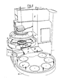
- a system for charging the jigs in the machine is provided.
- Such jigs are arranged on a idling plate the same form of the lapping plate.
- Such idling plate is approached to a chute connected to the lower lapping plate at an opening in the circular body of the lapping machine.
- each jig is caused by the operator to slide up on the chute and to reach the lower lapping plate.
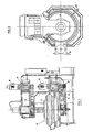
- the machine of this invention comprises a mount 2 from which an upper presser 4 descends downwards.In an underlying position a round iron sheet bucket which surrounds a lower lapping plate 8 on which a certain number of piece-holders 10 or satellites are arranged at constant angle distances. Plate 8 has at its center a large circular cavity at the center of which a wheel is disposed which is provided at its periphery with a crown of vertical dragging studs or teeth 2 with which the peripheries 10a are engaged of the satellites disposed on the lower plate.
- Satellites 10 are also surrounded by a crown of stationary studs 14 with which they engage always with the exterior periphery.
- Such studs can be lowered below the plate plane for allowing the satellites to slip out.
- Satellites 10 are pressed between the lower plate and the upper plate and are motor driven both about the axis of the machine and about their own center.
- the lapping machine 17 is provided with a motor 18 which actuates the upper plate through belt 19 and by a motor 20 which actuates the lower lapping plate through belt 24.
- Motor 18 and 20 provided with gear reducers 26 and 28 drive each one of the two lapping plates and have therefore the same power.
- the upper lapping plate gives the pieces to be lapped, a downwards thrust which is generated in addition to the weight, by hydraulic pressure which thrust produces the rubbing that is the lapping of the pieces contained over the satellite.
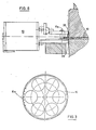
- Fig.5 the manoeuvre is illustrated for charging the satellite on the lower plate.
- Suitable handles facilitate the operator's task for rotating the table in the suitable direction.Supposing that the lapping machine comprises six satellites as illustrated in Fig.5 the support table will have the capacity of seven satellites.
- a plane 34 provided with a side slide 32 is inserted between the same support table and the lapping machine.
- a device for measuring the thickness attained by each piece which takes part on the lot being machined, a device (Fig.4) is provided which is called comparator 50 adapted for measuring the distance between a point (pont A) of the tangential horizontal upper plane of the piece and the point (point - B) which lies (at the beginning) on the same vertical but belongs to the tangential lower surface of the same piece.
- the comparator 50 device (Fig.2 and 6) is provided with an upper point 36 and a lower point 38, both being diamond points which hold therebetween, as shears, a limb circularly projecting from each of the rotating satellites in which limb at least one of the pieces to be lapped is partially included.
- the comparator can for instance be located at the place of one of the studs or teeth 14 with which the outer periphery of each satellite is engaged.
- the comparator device verifies the lowering of the piece and then of its vertical dimension and consequently it interrupts the working cycle and at the same time it sums successive rotations, that is angular lowerings and activates the recovering of the plate wear device.
- transducer 52 which transforms an electrical signal at the output of the comparator 50 into a control for the piston 46 which,- through a jack 48 produces the rotation of a screw 45 which lowers the support assembly 47,49 of comparator 50.
Landscapes
- Engineering & Computer Science (AREA)
- Mechanical Engineering (AREA)
- Finish Polishing, Edge Sharpening, And Grinding By Specific Grinding Devices (AREA)
Applications Claiming Priority (2)
| Application Number | Priority Date | Filing Date | Title |
|---|---|---|---|
| IT47738/86A IT1190231B (it) | 1986-03-07 | 1986-03-07 | Lappatrice a due plato' con dispositivo per la misura spessore del pezzo in lavorazione e con tavola di caricamento manuale dei satelliti |
| IT4773886 | 1986-03-07 |
Publications (3)
| Publication Number | Publication Date |
|---|---|
| EP0241433A2 true EP0241433A2 (de) | 1987-10-14 |
| EP0241433A3 EP0241433A3 (en) | 1989-07-26 |
| EP0241433B1 EP0241433B1 (de) | 1992-08-19 |
Family
ID=11262207
Family Applications (1)
| Application Number | Title | Priority Date | Filing Date |
|---|---|---|---|
| EP87830086A Expired - Lifetime EP0241433B1 (de) | 1986-03-07 | 1987-03-05 | Zweischeiben-Läppmaschine mit Komparator zum ununterbrochenen Messen der Werkstückdicke |
Country Status (3)
| Country | Link |
|---|---|
| EP (1) | EP0241433B1 (de) |
| DE (1) | DE3781188T2 (de) |
| IT (1) | IT1190231B (de) |
Cited By (4)
| Publication number | Priority date | Publication date | Assignee | Title |
|---|---|---|---|---|
| EP0344548A3 (de) * | 1988-05-28 | 1990-08-16 | Peter Wolters Ag | Verfahren und Vorrichtung zur Steuerung des Betriebs von Hon- oder Schleifmaschinen |
| EP0481935A3 (en) * | 1990-10-19 | 1992-09-02 | Melchiorre Officina Meccanica S.R.L. | Method and apparatus for the post-process check of the workpieces in a double-plate lapping machine |
| DE10007390B4 (de) * | 1999-03-13 | 2008-11-13 | Peter Wolters Gmbh | Zweischeiben-Poliermaschine, insbesondere zur Bearbeitung von Halbleiterwafern |
| CN115808145A (zh) * | 2022-12-02 | 2023-03-17 | 江苏希太芯科技有限公司 | 一种用于晶圆厚度多点测量装置及方法 |
Family Cites Families (3)
| Publication number | Priority date | Publication date | Assignee | Title |
|---|---|---|---|---|
| US3097458A (en) * | 1960-05-13 | 1963-07-16 | Method of accurately machining semiconductor bodies | |
| US3304662A (en) * | 1964-04-28 | 1967-02-21 | Speedlap Corp | Apparatus for lapping |
| JPS57168109A (en) * | 1981-04-10 | 1982-10-16 | Shinetsu Eng Kk | Device for measuring thickness of work piece in lapping plate |
-
1986
- 1986-03-07 IT IT47738/86A patent/IT1190231B/it active
-
1987
- 1987-03-05 EP EP87830086A patent/EP0241433B1/de not_active Expired - Lifetime
- 1987-03-05 DE DE8787830086T patent/DE3781188T2/de not_active Expired - Lifetime
Cited By (5)
| Publication number | Priority date | Publication date | Assignee | Title |
|---|---|---|---|---|
| EP0344548A3 (de) * | 1988-05-28 | 1990-08-16 | Peter Wolters Ag | Verfahren und Vorrichtung zur Steuerung des Betriebs von Hon- oder Schleifmaschinen |
| EP0481935A3 (en) * | 1990-10-19 | 1992-09-02 | Melchiorre Officina Meccanica S.R.L. | Method and apparatus for the post-process check of the workpieces in a double-plate lapping machine |
| DE10007390B4 (de) * | 1999-03-13 | 2008-11-13 | Peter Wolters Gmbh | Zweischeiben-Poliermaschine, insbesondere zur Bearbeitung von Halbleiterwafern |
| CN115808145A (zh) * | 2022-12-02 | 2023-03-17 | 江苏希太芯科技有限公司 | 一种用于晶圆厚度多点测量装置及方法 |
| CN115808145B (zh) * | 2022-12-02 | 2023-09-01 | 江苏希太芯科技有限公司 | 一种用于晶圆厚度多点测量装置及方法 |
Also Published As
| Publication number | Publication date |
|---|---|
| IT1190231B (it) | 1988-02-16 |
| DE3781188T2 (de) | 1992-12-17 |
| EP0241433B1 (de) | 1992-08-19 |
| DE3781188D1 (de) | 1992-09-24 |
| EP0241433A3 (en) | 1989-07-26 |
| IT8647738A0 (it) | 1986-03-07 |
Similar Documents
| Publication | Publication Date | Title |
|---|---|---|
| US4916868A (en) | Honing, lapping or polishing machine | |
| US3888050A (en) | Method of and apparatus for rapidly and simultaneously abrading metal workpieces in preselected plural numbers | |
| US4712332A (en) | Centerless and center-type grinding system | |
| US5108117A (en) | Workpart chuck positioning mechanism with independent shoes | |
| US4760668A (en) | Surface grinding machine and method | |
| US4507896A (en) | Centerless grinding systems | |
| US4031669A (en) | Automatic profiling machine | |
| US4823061A (en) | Stone expansion control for a honing machine | |
| EP0241433A2 (de) | Zweischeiben-Läppmaschine mit Komparator zum ununterbrochenen Messen der Werkstückdicke | |
| US5213348A (en) | Workpart chuck positioning mechanism with independent shoes | |
| US4580370A (en) | Centerless and center-type grinding systems | |
| JPH01135446A (ja) | 工作機械の定寸装置 | |
| JP4052616B2 (ja) | 刃物研削方法および装置 | |
| US3769756A (en) | Automatic grinding and machining apparatus | |
| US4085551A (en) | Grinding machines | |
| US4856232A (en) | Workpiece carrier means for surface grinding machine | |
| JPS6368364A (ja) | 平面研削機の研削方法 | |
| CN209647725U (zh) | 一种全自动板材异形切割机 | |
| CA1204941A (en) | Control system for grinding apparatus | |
| JPH0575548B2 (de) | ||
| CN117047574B (zh) | 一种磨料砂轮外圆加工装置 | |
| US3864880A (en) | Blade sharpening apparatus | |
| CN216668589U (zh) | 航空机械尺寸测量装置 | |
| JP2590976B2 (ja) | 砥石整形装置 | |
| JPH0579455B2 (de) |
Legal Events
| Date | Code | Title | Description |
|---|---|---|---|
| PUAI | Public reference made under article 153(3) epc to a published international application that has entered the european phase |
Free format text: ORIGINAL CODE: 0009012 |
|
| AK | Designated contracting states |
Kind code of ref document: A2 Designated state(s): CH DE FR GB LI |
|
| PUAL | Search report despatched |
Free format text: ORIGINAL CODE: 0009013 |
|
| AK | Designated contracting states |
Kind code of ref document: A3 Designated state(s): CH DE FR GB LI |
|
| 17P | Request for examination filed |
Effective date: 19900119 |
|
| 17Q | First examination report despatched |
Effective date: 19910129 |
|
| GRAA | (expected) grant |
Free format text: ORIGINAL CODE: 0009210 |
|
| AK | Designated contracting states |
Kind code of ref document: B1 Designated state(s): CH DE FR GB LI |
|
| REF | Corresponds to: |
Ref document number: 3781188 Country of ref document: DE Date of ref document: 19920924 |
|
| ET | Fr: translation filed | ||
| PG25 | Lapsed in a contracting state [announced via postgrant information from national office to epo] |
Ref country code: GB Effective date: 19930305 |
|
| PLBI | Opposition filed |
Free format text: ORIGINAL CODE: 0009260 |
|
| 26 | Opposition filed |
Opponent name: PETER WOLTERS AG Effective date: 19930518 |
|
| GBPC | Gb: european patent ceased through non-payment of renewal fee |
Effective date: 19930305 |
|
| PGFP | Annual fee paid to national office [announced via postgrant information from national office to epo] |
Ref country code: DE Payment date: 19940810 Year of fee payment: 8 |
|
| PGFP | Annual fee paid to national office [announced via postgrant information from national office to epo] |
Ref country code: CH Payment date: 19940817 Year of fee payment: 8 |
|
| PGFP | Annual fee paid to national office [announced via postgrant information from national office to epo] |
Ref country code: FR Payment date: 19940826 Year of fee payment: 8 |
|
| RDAG | Patent revoked |
Free format text: ORIGINAL CODE: 0009271 |
|
| STAA | Information on the status of an ep patent application or granted ep patent |
Free format text: STATUS: PATENT REVOKED |
|
| REG | Reference to a national code |
Ref country code: CH Ref legal event code: PL |
|
| 27W | Patent revoked |
Effective date: 19950213 |
|
| PLAB | Opposition data, opponent's data or that of the opponent's representative modified |
Free format text: ORIGINAL CODE: 0009299OPPO |