EP0241412B1 - Dispositif pour le montage de déclencheurs auxiliaires - Google Patents
Dispositif pour le montage de déclencheurs auxiliaires Download PDFInfo
- Publication number
- EP0241412B1 EP0241412B1 EP87730034A EP87730034A EP0241412B1 EP 0241412 B1 EP0241412 B1 EP 0241412B1 EP 87730034 A EP87730034 A EP 87730034A EP 87730034 A EP87730034 A EP 87730034A EP 0241412 B1 EP0241412 B1 EP 0241412B1
- Authority
- EP
- European Patent Office
- Prior art keywords
- auxiliary
- shaft
- carrier plate
- assembly
- tripping units
- Prior art date
- Legal status (The legal status is an assumption and is not a legal conclusion. Google has not performed a legal analysis and makes no representation as to the accuracy of the status listed.)
- Expired - Lifetime
Links
- 230000009471 action Effects 0.000 claims description 4
- 230000005540 biological transmission Effects 0.000 claims description 2
- 210000000056 organ Anatomy 0.000 claims 2
- 230000006870 function Effects 0.000 description 3
- 238000009434 installation Methods 0.000 description 2
- 230000003993 interaction Effects 0.000 description 2
- 238000000034 method Methods 0.000 description 2
- 230000008569 process Effects 0.000 description 2
- 230000001960 triggered effect Effects 0.000 description 2
- 230000008878 coupling Effects 0.000 description 1
- 238000010168 coupling process Methods 0.000 description 1
- 238000005859 coupling reaction Methods 0.000 description 1
- 230000005284 excitation Effects 0.000 description 1
- 230000007246 mechanism Effects 0.000 description 1
- 239000000523 sample Substances 0.000 description 1
Images

Classifications
-
- H—ELECTRICITY
- H01—ELECTRIC ELEMENTS
- H01H—ELECTRIC SWITCHES; RELAYS; SELECTORS; EMERGENCY PROTECTIVE DEVICES
- H01H83/00—Protective switches, e.g. circuit-breaking switches, or protective relays operated by abnormal electrical conditions otherwise than solely by excess current
- H01H83/20—Protective switches, e.g. circuit-breaking switches, or protective relays operated by abnormal electrical conditions otherwise than solely by excess current operated by excess current as well as by some other abnormal electrical condition
-
- H—ELECTRICITY
- H01—ELECTRIC ELEMENTS
- H01H—ELECTRIC SWITCHES; RELAYS; SELECTORS; EMERGENCY PROTECTIVE DEVICES
- H01H71/00—Details of the protective switches or relays covered by groups H01H73/00 - H01H83/00
- H01H71/02—Housings; Casings; Bases; Mountings
- H01H71/0207—Mounting or assembling the different parts of the circuit breaker
- H01H71/0228—Mounting or assembling the different parts of the circuit breaker having provisions for interchangeable or replaceable parts
Definitions
- the invention relates to an arrangement for mounting auxiliary triggers in a switching device, which has a trigger shaft and as a component of the supporting structure of the switching device, a wall with a mounting plate provided for attachment to the wall with fasteners, which are dimensioned for the most extensive configuration with auxiliary triggers and has mounting spaces designed to accommodate certain types of auxiliary releases.
- Shunt releases or undervoltage releases can be considered as auxiliary releases; a switching device can be triggered remotely or inevitably triggered when the voltage falls below a certain value. If the switching device is a low-voltage circuit breaker which has a storage drive, it may also be desirable to be able to remotely switch on by means of a further shunt release. It may also be desirable to secure the circuit breaker against reclosing if tripping has occurred due to overcurrent, short circuit or undervoltage. These processes can also be achieved using auxiliary triggers of suitable designs.
- auxiliary release In US-A-4'166'260 only a single auxiliary release is described, which can optionally be mounted in a switching device.
- the auxiliary release according to FIG. 2 has a holding bridge which, instead of an otherwise used separating piece, can be inserted into a dividing wall between adjacent pole tracks of a compact circuit breaker.
- the auxiliary trigger interacts directly with the trigger shaft 38 of the switching device, thus without an intermediate shaft.
- only one auxiliary release can be used in the manner described.
- the US-A-4'246'558 relates to switching devices that can be supplemented in a modular manner by additional parts, each of which performs the function of an auxiliary release.
- a separate housing is provided for each such auxiliary release, which is attached laterally parallel to the actual switching device.
- a total of three coupling points are provided for the transmission of a switching movement as well as a reset and release movement, which must be brought into engagement when the auxiliary modules are mounted on the side.
- the invention has for its object to provide an arrangement which allows the switching device to be provided with a simple or with the most comprehensive possible equipment of auxiliary releases with little effort and for which the restriction according to US-A-4 097 831 to overcome and one appropriate to the different requirements To enable assembly with auxiliary triggers.
- auxiliary releases can be installed and checked outside the switchgear.
- the finished and functional unit can then be inserted into the switching device without difficulty, since the form-fitting fastening means ensure interaction with the trigger shaft of the switching device without special adjustment.
- the carrier plate and the auxiliary shaft can still be used with different equipment with auxiliary triggers, since thanks to the arrangement of tactile fingers, different auxiliary triggers can be mounted at one and the same place on the carrier plate. The deviating from the previous design locally frame-like design of the support plate allows to achieve the greatest possible depth of installation with good mechanical stability.
- the auxiliary shaft only requires a relatively simple storage, since it only needs to execute a small swivel angle in order to actuate the trigger shaft.
- the auxiliary shaft can have a bearing journal at one end and, at a suitable distance therefrom, at least one shaft section provided for mounting in a half-shell-like recess in the carrier plate. The auxiliary shaft can then only be installed by inserting its journal into a bearing opening in the carrier plate and attaching a suitable cover plate.
- a connection to the trigger shaft is established automatically when the carrier plate is inserted into the switching device.
- this driver can additionally have at least one additional work surface for direct loading by one of the auxiliary triggers. This makes it possible to assign the auxiliary shaft to those auxiliary triggers which are arranged at a distance from the tripping shaft, while auxiliary triggers adjacent to the tripping shaft can interact directly with the driver.
- the switching device also has a trigger shaft for a switch-on memory
- the mounting plate with a mounting location for an auxiliary release provided for triggering the switch-on memory, ie for switching on the switchgear.
- This auxiliary release can expediently interact directly with the associated release shaft. If, however, it should be cheaper for reasons of spatial allocation, this can also be the case use of the auxiliary shaft.
- Figures 1 and 2 show an arrangement of auxiliary triggers in plan view and in a side view with adjacent parts of a low-voltage circuit breaker.
- FIG. 3 shows an auxiliary shaft of the arrangement according to FIGS. 1 and 2.
- FIGS. 4 and 5 show a view of the auxiliary shaft according to FIG. 3 in the direction of arrow IV in FIG. 3 or a section V-V in FIG. 3.
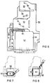
- FIG. 6 shows a carrier plate for an auxiliary release arrangement in a top view.
- FIGS. 7 and 8 show, in a representation that is reduced compared to FIG. 6, the equipping of an assembly location of the carrier plate according to FIG. 6 with different auxiliary triggers.
- the auxiliary release arrangement designated as a whole by 1 in FIGS. 1 and 2 is mounted on a wall 2, which is part of the supporting structure of a low-voltage circuit breaker.
- the wall 2 can be an intermediate wall in which the drive shafts and tripping shafts of the circuit breaker are mounted.
- the auxiliary trigger arrangement 1 comprises a carrier plate 3, which can preferably consist of a suitable plastic.
- the carrier plate 3 On its underside, the carrier plate 3 has at least two pins 4, openings 2 of which are provided in the wall for receiving them. In this way, the carrier plate 3 can be inserted dimensionally into the circuit breaker without adjustment. Screws are sufficient for fastening, for which a through opening 5 and a laterally open recess 6 are provided on the edge of the carrier plate 3.
- the carrier plate 3 is equipped with a total of four auxiliary releases, namely an undervoltage release 7, a shunt release 10, a restart lock 11 and a solenoid 12.
- the auxiliary releases 7, 10 and 11 act on a trigger shaft 13 on which a driver 14 is placed.
- the trigger shaft 13 is part of the circuit breaker of the circuit breaker and is used to latch the contact apparatus of the circuit breaker in the closed position and to be able to release this latching again.
- the circuit breaker has a spring accumulator which serves to store the switch-on energy.
- a tripping shaft also belongs to this energy store, by actuating it the energy store can be released so that the circuit breaker is switched on.
- the retrieval magnet 12 serves as a separate auxiliary trigger for the remote-controlled implementation of such a switch-on.
- the relevant trigger shaft has been omitted in FIGS. 1 and 2 to improve clarity.
- the auxiliary trigger 7 is located at such a distance from the trigger shaft 13 and the driver 14 seated thereon that a direct action on the driver 13 by the trigger member 15 of the auxiliary trigger 7 is not possible.
- the trigger movement is transmitted in a surprisingly simple manner by means of an auxiliary shaft 16 which is pivotably mounted on the carrier plate 3.
- the auxiliary shaft 16 has at one end a bearing pin 17 and at a suitable distance therefrom a cylindrical section 20 suitable for storage. With the bearing pin 17, the auxiliary shaft 16 engages in a bearing opening 21 in a lower, angled end part 22 of the carrier plate 3 a.
- the cylindrical section 20 lies in an approximately half-shell-shaped recess 23 (FIG. 2) of the carrier plate 3. In this position, the auxiliary shaft 16 is secured by a cover piece 24.
- the auxiliary shaft 16 has at its end opposite the journal 17 a finger 25, the shape of which can be seen in detail in FIG. With this touch finger, the auxiliary shaft 16 interacts with an extension 26 of the driver 14, so that the movements of the auxiliary shaft 16 can be transmitted to the trigger shaft 13 in this way.
- the touch finger 25 is dimensioned such that it does not protrude into the path of a trigger member 27 of the auxiliary trigger 10 and this trigger member can thus act directly on the extension 26 of the driver 14.
- auxiliary shaft 16 which can be seen in greater detail in FIGS. 2 and 3, are located in the region of the auxiliary trigger 7, the trigger element 15 interacting with the tactile finger 32. If the mounting location of the support plate 3, at which in FIGS Auxiliary trigger 7 is located, equipped with other auxiliary triggers, the trigger force can also be applied to the touch finger 30 or the touch finger 31. The trigger movement is always transmitted to the trigger shaft 13 by means of the auxiliary shaft 16.
- the trigger shaft 16 is provided with an extension 33 which is arranged near the touch finger 25.
- the shape of this extension is shown in more detail in FIGS. 3 and 5.
- the extension 33 is provided with a through opening 34, which is used to hang a helical tension spring in order to be able to introduce a restoring force into the auxiliary shaft 16.
- the auxiliary release 11 is a restart lock. It is a magnet system which is attracted in its rest position by means of a permanent magnet or by permanent excitation and which can be released by de-excitation or overcoming the holding force of the permanent magnet. A spring mechanism then brings the auxiliary release into the released state, in which a pull rod 35 with an angled end 36 acts on a further extension 37 of the driver 14. The trigger shaft 13 then remains in its trigger position until the restart lock is reset. An auxiliary switch 40 is actuated by means of the pull rod 37 in the manner shown in FIG. 1, which thus signals the position of the trigger shaft 13.
- a third extension 41 of the driver 14 is provided to transmit a trigger movement by an actuating magnet, not shown, in the direction of an arrow 42 to the trigger shaft 13.
- This actuating magnet can in particular be controlled by an electronic tripping unit which responds to overcurrent and short-circuit in accordance with predefined characteristic curves.
- FIG. 6 a carrier plate 50 largely corresponding to the carrier plate 3 in FIGS. 1 and 2 is shown only together with a trigger shaft 51. Based on this representation, the mounting locations of the carrier plate can be recognized by the auxiliary releases.
- a total of four assembly stations 52, 53, 54 and 55 are provided, which are provided with suitable fastening means, for example the bores or through holes 56, 57 and 58 shown in the region of the assembly stations 53, 54 and 55.
- the carrier plate 50 is designed like a frame with an opening 60. At this point, the greatest possible mounting depth is available, since an auxiliary trigger to be mounted here - apart from a necessary small space - can extend to wall 2 (FIGS. 1 and 2).
- FIG. 6 also shows a tension coil spring 64 which acts on the auxiliary shaft 51 in the same manner as was explained with reference to FIGS. 3 and 5 using the example of the auxiliary shaft 16.
- the carrier plate 50 can be provided with one or more auxiliary triggers up to the intended maximum configuration of four auxiliary triggers.
- Different auxiliary releases can be installed in the area of the assembly site 52.
- FIG. 7 shows the assembly location 52 being equipped with a shunt release 61 which is only of a relatively small size and thus only partially utilizes the available space. Proper interaction of the release member 62 of the shunt release 61 with the auxiliary shaft 51 is ensured by the fact that the latter has adjacent finger fingers in the manner already described.
- a larger auxiliary release 63 is shown in FIG. B. an undervoltage release, which accordingly dips into the opening 60 of the support plate 50 and fully utilizes the assembly space 52.
- the other assembly stations 53, 54 and 55 are each provided in the example shown for fitting with a specific type of auxiliary release; However, it is easy to see that these assembly stations can also be equipped with auxiliary releases of different functions and sizes if necessary.
Landscapes
- Breakers (AREA)
- Operating, Guiding And Securing Of Roll- Type Closing Members (AREA)
- Arrangement And Mounting Of Devices That Control Transmission Of Motive Force (AREA)
- Air Bags (AREA)
Claims (4)
- Dispositif pour le montage de déclencheurs auxiliaires (7,10,11,12;61,63) dans un appareil de coupure, qui comporte un arbre de déclenchement (13) et, en tant que partie de l'unité de support de l'appareil de coupure, une paroi (2), et comportant une plaque de support (3;50) qui est équipée de moyens de fixation pour son montage, selon des dimensions correctes, à la paroi (2) et qui est dimensionnée pour son équipement très diversifié, envisagé, avec des déclencheurs auxiliaires (7,10,11,12; 61,63) et possède des emplacements de montage (52,53,54,55) dimensionnés pour la réception de types déterminés de déclencheurs auxiliaires; caractérisé par les caractéristiques suivantes:a) les moyens de fixation (4) sont agencés de manière à coopérer selon une liaison par formes complémentaires avec la paroi (2),b) au moins l'un des emplacements de montage (52) est agencé de manière à pouvoir être équipé au choix avec des déclencheurs auxiliaires (61,63) ayant des fonctions et/ou des tailles différentes, et la plaque de support (5) est agencée, avec une partie de cet emplacement de montage (50), pour l'obtention d'une profondeur de montage maximale possible, sous la forme d'un cadre présentant un perçage (60),c) sur la plaque de support (3;50) est monté un arbre auxiliaire (16) servant à transmettre le mouvement de déclenchement des déclencheurs auxiliaires (7,10,11,12; 61,63) à l'arbre de déclenchement (16) de l'appareil de coupure,d) l'arbre auxiliaire (16) possède des doigts palpeurs (30,31,32), qui sont destinés à être chargés par des organes de déclenchement (15) des déclencheurs auxiliaires (17) et dont la longueur et la disposition sont conçues d'une manière adaptée à la position des organes auxiliaires (15), qui est possible dans le cas d'un équipement variable de la plaque de support (3;50) avec des déclencheurs auxiliaires, ete) l'arbre auxiliaire (16) est équipé, au niveau de l'emplacement de montage pouvant être équipé au choix, de deux ou plusieurs doigts palpeurs (31,32) selon une configuration adaptée du point de vue de la taille et de la position aux différents équipements.
- Dispositif selon la revendication 1, caractérisé par le fait que l'arbre auxiliaire (16) possède, à un extrémité, un tourillon (17) ainsi qu'à une distance appropriée de ces derniers, au moins un élément d'arbre (20) destiné à être tourillonné dans un évidement en forme de demi-coque (23) de la plaque de support (3).
- Dispositif suivant la revendication 1, caractérisé par le fait que l'arbre auxiliaire (16) possède un doigt palpeur (25) servant à charger un organe d'entraînement (14) monté sur l'arbre de déclenchement (13), et que l'organe d'entraînement (14) comporte au moins une surface supplémentaire de travail (28) destinée à être chargée directement par l'un des déclencheurs auxiliaires (10).
- Dispositif suivant la revendication 1, caractérisé par le fait que la plaque de support (3) possède au moins un emplacement de montage pour un autre déclencheur auxiliaire (12) qui coopère avec un arbre supplémentaire de déclenchement de l'appareil de coupure.
Applications Claiming Priority (2)
| Application Number | Priority Date | Filing Date | Title |
|---|---|---|---|
| DE19863612119 DE3612119A1 (de) | 1986-04-08 | 1986-04-08 | Anordnung zur montage von hilfsausloesern |
| DE3612119 | 1986-04-08 |
Publications (2)
| Publication Number | Publication Date |
|---|---|
| EP0241412A1 EP0241412A1 (fr) | 1987-10-14 |
| EP0241412B1 true EP0241412B1 (fr) | 1992-03-04 |
Family
ID=6298409
Family Applications (1)
| Application Number | Title | Priority Date | Filing Date |
|---|---|---|---|
| EP87730034A Expired - Lifetime EP0241412B1 (fr) | 1986-04-08 | 1987-04-06 | Dispositif pour le montage de déclencheurs auxiliaires |
Country Status (2)
| Country | Link |
|---|---|
| EP (1) | EP0241412B1 (fr) |
| DE (2) | DE3612119A1 (fr) |
Cited By (1)
| Publication number | Priority date | Publication date | Assignee | Title |
|---|---|---|---|---|
| CN106229235A (zh) * | 2016-08-13 | 2016-12-14 | 郑文秀 | 一种自动重合闸驱动机构 |
Families Citing this family (9)
| Publication number | Priority date | Publication date | Assignee | Title |
|---|---|---|---|---|
| US4887055A (en) * | 1988-08-01 | 1989-12-12 | Westinghouse Electric Corp. | Modular option deck assembly |
| DE3909553A1 (de) * | 1989-03-20 | 1990-09-27 | Siemens Ag | Leistungsschalter mit einem unterspannungsausloeser |
| DE4421150C1 (de) * | 1994-06-10 | 1996-01-04 | Siemens Ag | Anordnung zur lösbaren Befestigung einer Baugruppe |
| DE19802921A1 (de) * | 1998-01-21 | 1999-07-22 | Siemens Ag | Niederspannungs-Leistungsschalter mit einem Hilfsauslöser |
| DE19806345A1 (de) * | 1998-02-12 | 1999-08-19 | Siemens Ag | Verfahren und Vorrichtung zum Betrieb eines Leistungsschalters |
| EP0951045A3 (fr) * | 1998-04-14 | 2000-07-12 | ABBPATENT GmbH | Disjoncteur à courant de défaut |
| CZ300000B6 (cs) * | 2001-09-10 | 2009-01-14 | Lekov A.S. | Jistic proti proudovému pretížení stejnosmerného proudového obvodu |
| DE10246479B4 (de) * | 2002-09-27 | 2004-09-09 | Siemens Ag | Niederspannungs-Leistungsschalter mit zusätzlicher Schnellauslösung |
| CN105336522A (zh) * | 2015-11-09 | 2016-02-17 | 川开电气有限公司 | 熔断器脱扣联锁机构 |
Family Cites Families (5)
| Publication number | Priority date | Publication date | Assignee | Title |
|---|---|---|---|---|
| US3521127A (en) * | 1967-10-13 | 1970-07-21 | Airpax Electronics | Remotely operated circuit breaker |
| US3919674A (en) * | 1974-11-26 | 1975-11-11 | Gen Electric | Accessory apparatus for tripping an electric circuit breaker |
| US4097831A (en) * | 1977-01-21 | 1978-06-27 | General Electric Company | Circuit breaker accessory tripping apparatus |
| US4166260A (en) * | 1978-03-29 | 1979-08-28 | General Electric Company | Circuit breaker accessory assembly |
| US4246558A (en) * | 1979-01-22 | 1981-01-20 | Gould Inc. | Auxiliary feature modules for circuit breakers |
-
1986
- 1986-04-08 DE DE19863612119 patent/DE3612119A1/de not_active Withdrawn
-
1987
- 1987-04-06 DE DE8787730034T patent/DE3776942D1/de not_active Expired - Lifetime
- 1987-04-06 EP EP87730034A patent/EP0241412B1/fr not_active Expired - Lifetime
Cited By (1)
| Publication number | Priority date | Publication date | Assignee | Title |
|---|---|---|---|---|
| CN106229235A (zh) * | 2016-08-13 | 2016-12-14 | 郑文秀 | 一种自动重合闸驱动机构 |
Also Published As
| Publication number | Publication date |
|---|---|
| EP0241412A1 (fr) | 1987-10-14 |
| DE3776942D1 (de) | 1992-04-09 |
| DE3612119A1 (de) | 1987-10-22 |
Similar Documents
| Publication | Publication Date | Title |
|---|---|---|
| DE3421765C2 (de) | Rücksetzbarer Schutzschalter mit Unterspannungsauslösung | |
| DE2116637B2 (de) | Elektrisch betätigbare Entriegelungsanordnung in einem Türöffner | |
| EP0606264A1 (fr) | Interrupteur a vide avec un dispositif d'actionnement et une unite d'actionnement polaire. | |
| DE102006024994B3 (de) | Elektronischer Schalter | |
| EP0241412A1 (fr) | Dispositif pour le montage de déclencheurs auxiliaires | |
| EP2633537B1 (fr) | Serrure à carte | |
| DE60312169T2 (de) | Antriebsvorrichtung und verfahren zum betrieb einer schaltanordnung | |
| DE102021125906A1 (de) | Wandhalterung zur Befestigung eines medizinischen Gerätes | |
| DE3433604A1 (de) | Betaetigungsvorrichtung fuer elektrische schalter | |
| CH690345A5 (de) | Abgedichteter elektrischer Schalter und Schalteranordnung. | |
| DE1805583C3 (de) | Steckbares elektromagnetisches Relais | |
| DE2149132C3 (de) | Trennschalter | |
| WO1986000751A1 (fr) | Verrou de commutation | |
| DE69812626T2 (de) | Sperr- und sicherungsmittel für bewegliche schalterbetätigung | |
| DE19846219B4 (de) | Stromschalter | |
| AT379254B (de) | Elektromagnetisches klappanker-relais mit zwangsgefuehrten kontakten | |
| DE4421150C1 (de) | Anordnung zur lösbaren Befestigung einer Baugruppe | |
| DE10117066A1 (de) | Leitungsschutzschalter | |
| DE2027330C3 (de) | Elektromagnetisches Flachrelais | |
| EP0389075B1 (fr) | Disjoncteur avec un déclencheur à minimum de tension | |
| EP0105516B1 (fr) | Agencement de commutateur | |
| DE19948695B4 (de) | Niederspannungs-Leistungsschalter mit einem bewegbaren Kontaktträger mit Endlagen-Haltefeder | |
| DE3425996C2 (fr) | ||
| DE2210906C3 (de) | Sprechstelle für eine Wechselsprechanlage | |
| DE102004026122B4 (de) | Schutzschaltvorrichtung mit biegbarem Justierhebel und entsprechendes Justierverfahren |
Legal Events
| Date | Code | Title | Description |
|---|---|---|---|
| PUAI | Public reference made under article 153(3) epc to a published international application that has entered the european phase |
Free format text: ORIGINAL CODE: 0009012 |
|
| AK | Designated contracting states |
Kind code of ref document: A1 Designated state(s): DE FR IT SE |
|
| 17P | Request for examination filed |
Effective date: 19871106 |
|
| 17Q | First examination report despatched |
Effective date: 19900312 |
|
| GRAA | (expected) grant |
Free format text: ORIGINAL CODE: 0009210 |
|
| AK | Designated contracting states |
Kind code of ref document: B1 Designated state(s): DE FR IT SE |
|
| REF | Corresponds to: |
Ref document number: 3776942 Country of ref document: DE Date of ref document: 19920409 |
|
| ET | Fr: translation filed | ||
| ITF | It: translation for a ep patent filed | ||
| PLBE | No opposition filed within time limit |
Free format text: ORIGINAL CODE: 0009261 |
|
| STAA | Information on the status of an ep patent application or granted ep patent |
Free format text: STATUS: NO OPPOSITION FILED WITHIN TIME LIMIT |
|
| 26N | No opposition filed | ||
| EAL | Se: european patent in force in sweden |
Ref document number: 87730034.3 |
|
| PGFP | Annual fee paid to national office [announced via postgrant information from national office to epo] |
Ref country code: SE Payment date: 19950424 Year of fee payment: 9 |
|
| PG25 | Lapsed in a contracting state [announced via postgrant information from national office to epo] |
Ref country code: SE Effective date: 19960407 |
|
| EUG | Se: european patent has lapsed |
Ref document number: 87730034.3 |
|
| PGFP | Annual fee paid to national office [announced via postgrant information from national office to epo] |
Ref country code: FR Payment date: 20010420 Year of fee payment: 15 |
|
| PGFP | Annual fee paid to national office [announced via postgrant information from national office to epo] |
Ref country code: DE Payment date: 20010620 Year of fee payment: 15 |
|
| PG25 | Lapsed in a contracting state [announced via postgrant information from national office to epo] |
Ref country code: DE Free format text: LAPSE BECAUSE OF NON-PAYMENT OF DUE FEES Effective date: 20021101 |
|
| PG25 | Lapsed in a contracting state [announced via postgrant information from national office to epo] |
Ref country code: FR Free format text: LAPSE BECAUSE OF NON-PAYMENT OF DUE FEES Effective date: 20021231 |
|
| REG | Reference to a national code |
Ref country code: FR Ref legal event code: ST |
|
| PG25 | Lapsed in a contracting state [announced via postgrant information from national office to epo] |
Ref country code: IT Free format text: LAPSE BECAUSE OF NON-PAYMENT OF DUE FEES;WARNING: LAPSES OF ITALIAN PATENTS WITH EFFECTIVE DATE BEFORE 2007 MAY HAVE OCCURRED AT ANY TIME BEFORE 2007. THE CORRECT EFFECTIVE DATE MAY BE DIFFERENT FROM THE ONE RECORDED. Effective date: 20050406 |