EP0241388B1 - Rollenschneidmaschine - Google Patents
Rollenschneidmaschine Download PDFInfo
- Publication number
- EP0241388B1 EP0241388B1 EP87420071A EP87420071A EP0241388B1 EP 0241388 B1 EP0241388 B1 EP 0241388B1 EP 87420071 A EP87420071 A EP 87420071A EP 87420071 A EP87420071 A EP 87420071A EP 0241388 B1 EP0241388 B1 EP 0241388B1
- Authority
- EP
- European Patent Office
- Prior art keywords
- cylinder
- frame
- cutting
- rollers
- pressure plate
- Prior art date
- Legal status (The legal status is an assumption and is not a legal conclusion. Google has not performed a legal analysis and makes no representation as to the accuracy of the status listed.)
- Expired - Lifetime
Links
Images
Classifications
-
- B—PERFORMING OPERATIONS; TRANSPORTING
- B21—MECHANICAL METAL-WORKING WITHOUT ESSENTIALLY REMOVING MATERIAL; PUNCHING METAL
- B21H—MAKING PARTICULAR METAL OBJECTS BY ROLLING, e.g. SCREWS, WHEELS, RINGS, BARRELS, BALLS
- B21H1/00—Making articles shaped as bodies of revolution
-
- B—PERFORMING OPERATIONS; TRANSPORTING
- B26—HAND CUTTING TOOLS; CUTTING; SEVERING
- B26D—CUTTING; DETAILS COMMON TO MACHINES FOR PERFORATING, PUNCHING, CUTTING-OUT, STAMPING-OUT OR SEVERING
- B26D7/00—Details of apparatus for cutting, cutting-out, stamping-out, punching, perforating, or severing by means other than cutting
- B26D7/26—Means for mounting or adjusting the cutting member; Means for adjusting the stroke of the cutting member
- B26D7/2628—Means for adjusting the position of the cutting member
- B26D7/265—Journals, bearings or supports for positioning rollers or cylinders relatively to each other
-
- B—PERFORMING OPERATIONS; TRANSPORTING
- B26—HAND CUTTING TOOLS; CUTTING; SEVERING
- B26D—CUTTING; DETAILS COMMON TO MACHINES FOR PERFORATING, PUNCHING, CUTTING-OUT, STAMPING-OUT OR SEVERING
- B26D7/00—Details of apparatus for cutting, cutting-out, stamping-out, punching, perforating, or severing by means other than cutting
- B26D7/26—Means for mounting or adjusting the cutting member; Means for adjusting the stroke of the cutting member
- B26D7/2614—Means for mounting the cutting member
-
- B—PERFORMING OPERATIONS; TRANSPORTING
- B26—HAND CUTTING TOOLS; CUTTING; SEVERING
- B26F—PERFORATING; PUNCHING; CUTTING-OUT; STAMPING-OUT; SEVERING BY MEANS OTHER THAN CUTTING
- B26F1/00—Perforating; Punching; Cutting-out; Stamping-out; Apparatus therefor
- B26F1/38—Cutting-out; Stamping-out
- B26F1/384—Cutting-out; Stamping-out using rotating drums
-
- Y—GENERAL TAGGING OF NEW TECHNOLOGICAL DEVELOPMENTS; GENERAL TAGGING OF CROSS-SECTIONAL TECHNOLOGIES SPANNING OVER SEVERAL SECTIONS OF THE IPC; TECHNICAL SUBJECTS COVERED BY FORMER USPC CROSS-REFERENCE ART COLLECTIONS [XRACs] AND DIGESTS
- Y10—TECHNICAL SUBJECTS COVERED BY FORMER USPC
- Y10T—TECHNICAL SUBJECTS COVERED BY FORMER US CLASSIFICATION
- Y10T83/00—Cutting
- Y10T83/465—Cutting motion of tool has component in direction of moving work
- Y10T83/4766—Orbital motion of cutting blade
- Y10T83/4795—Rotary tool
- Y10T83/483—With cooperating rotary cutter or backup
- Y10T83/4833—Cooperating tool axes adjustable relative to each other
-
- Y—GENERAL TAGGING OF NEW TECHNOLOGICAL DEVELOPMENTS; GENERAL TAGGING OF CROSS-SECTIONAL TECHNOLOGIES SPANNING OVER SEVERAL SECTIONS OF THE IPC; TECHNICAL SUBJECTS COVERED BY FORMER USPC CROSS-REFERENCE ART COLLECTIONS [XRACs] AND DIGESTS
- Y10—TECHNICAL SUBJECTS COVERED BY FORMER USPC
- Y10T—TECHNICAL SUBJECTS COVERED BY FORMER US CLASSIFICATION
- Y10T83/00—Cutting
- Y10T83/465—Cutting motion of tool has component in direction of moving work
- Y10T83/4766—Orbital motion of cutting blade
- Y10T83/4795—Rotary tool
- Y10T83/483—With cooperating rotary cutter or backup
- Y10T83/4838—With anvil backup
-
- Y—GENERAL TAGGING OF NEW TECHNOLOGICAL DEVELOPMENTS; GENERAL TAGGING OF CROSS-SECTIONAL TECHNOLOGIES SPANNING OVER SEVERAL SECTIONS OF THE IPC; TECHNICAL SUBJECTS COVERED BY FORMER USPC CROSS-REFERENCE ART COLLECTIONS [XRACs] AND DIGESTS
- Y10—TECHNICAL SUBJECTS COVERED BY FORMER USPC
- Y10T—TECHNICAL SUBJECTS COVERED BY FORMER US CLASSIFICATION
- Y10T83/00—Cutting
- Y10T83/465—Cutting motion of tool has component in direction of moving work
- Y10T83/4766—Orbital motion of cutting blade
- Y10T83/4795—Rotary tool
- Y10T83/483—With cooperating rotary cutter or backup
- Y10T83/4844—Resiliently urged cutter or anvil member
-
- Y—GENERAL TAGGING OF NEW TECHNOLOGICAL DEVELOPMENTS; GENERAL TAGGING OF CROSS-SECTIONAL TECHNOLOGIES SPANNING OVER SEVERAL SECTIONS OF THE IPC; TECHNICAL SUBJECTS COVERED BY FORMER USPC CROSS-REFERENCE ART COLLECTIONS [XRACs] AND DIGESTS
- Y10—TECHNICAL SUBJECTS COVERED BY FORMER USPC
- Y10T—TECHNICAL SUBJECTS COVERED BY FORMER US CLASSIFICATION
- Y10T83/00—Cutting
- Y10T83/929—Tool or tool with support
- Y10T83/9309—Anvil
- Y10T83/9312—Rotatable type
-
- Y—GENERAL TAGGING OF NEW TECHNOLOGICAL DEVELOPMENTS; GENERAL TAGGING OF CROSS-SECTIONAL TECHNOLOGIES SPANNING OVER SEVERAL SECTIONS OF THE IPC; TECHNICAL SUBJECTS COVERED BY FORMER USPC CROSS-REFERENCE ART COLLECTIONS [XRACs] AND DIGESTS
- Y10—TECHNICAL SUBJECTS COVERED BY FORMER USPC
- Y10T—TECHNICAL SUBJECTS COVERED BY FORMER US CLASSIFICATION
- Y10T83/00—Cutting
- Y10T83/929—Tool or tool with support
- Y10T83/9372—Rotatable type
Definitions
- the present invention relates to a rotary cutting or upsetting device (creation of crushing lines) of flat products, such as strips or blanks of paper, cardboard, fabric, plastic, wadding, etc., comprising in a rigid frame a cutting or delivery cylinder equipped with tools and a counter-part cylinder, or anvil, superimposed and with parallel axes supported and guided by bearings, the upper part of the frame comprising means for guiding a pressure plate carrying rollers or the like at its lower part for rolling and guiding the upper part of the upper cylinder, the pressure plate being associated with means for adjusting the bearing pressure of these rollers on the cylinder upper (see US-A 4,452,116).
- Continuous rotary cutters or upsetters which comprise a cutting or delivery cylinder equipped with tool (s), and working in cooperation with an anvil cylinder, also called counterpart or counter-cutting cylinder.
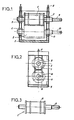
- such a rotary cutter of the known art comprises a cutting cylinder 1 and an anvil cylinder 2 superimposed and with parallel axes, which are fixed, by means of four rolling bearings 3-6, on a rigid frame 7.
- the cutting cylinder 1 is placed above the anvil cylinder 2.
- the two cylinders are pressed one against the other by means of screws 8 or jacks, the pressure force being communicated to the bearings 3-6 of these cylinders.
- the rotational drive is generally carried out by the shaft 9 of the cutting cylinder, sometimes also by the shaft 10 of the anvil cylinder.
- the bearings 3-6 provide the lateral and transverse guides of the cylinders 1,2 in the frame 7.
- the rigidity of the latter is essential to ensure a perfect cut. As soon as the cutting edge 11 has decreased by a few hundredths of a millimeter, the tool no longer cuts well enough, or no longer at all, and must therefore be replaced.
- the device for rotary cutting or pushing flat products does not have this type of drawback. It is characterized in that at the lower part of the frame is located a cradle on which rest rollers, or the like, for supporting, rolling and guiding the lower part of the lower cylinder, in that the shafts of the two cylinders are only supported and guided by bearings placed on one side of the frame, no bearing existing on the opposite side, in that the cutting or delivery cylinder and the anvil cylinder are both of tubular shape, so as to come to fit tightly on the corresponding shaft, the frame being equipped with passage (s) allowing the introduction and the withdrawal of these tubular cylinders by the side of the frame not having bearings.
- the immobilization of each of said tubular cylinders on the corresponding shaft is carried out by means of a shaft expansion device disposed in the axis thereof.
- the pressure plate is associated with force sensors making it possible to control the wear of the tool or tools and the value of the pressure applied to the cutting cylinder.
- the anvil cylinder comprises, inside its body, a pressure device allowing by external control to very slightly increase its diameter to compensate for the wear of the tool or tools.
- said pressure device is a device which can act locally, so as to vary locally, and in a controlled manner, the diameters of rolling from one cylinder to the other.
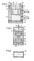
- a rotary cutter comprising, as is the case for the known rotary cutter of Figures 1 and 2 previously described, a rigid frame 7, a cutting cylinder 1 with drive shaft 9 and bearing bearing 3, an anvil cylinder 2 with shaft 10 and bearing 4.
- a cradle 12 carrying as shown four lower rollers 13.
- the upper part of the frame 7 has spacers 14 which serve as a guide for an upper pressure plate 15.
- This pressure plate 15 carries on its lower part four other rollers 16.
- the anvil cylinder 2 rests with all its weight on the lower rollers 13, while the upper rollers 16, which are as shown in the right of the lower rollers 13, bear on the upper part of the cutting cylinder 1.
- the upper and lower rollers form a set of contact lines which ensure the alignment of the respective generatrices of the cutting and anvil cylinders.
- the left part 31 of the frame is hollow, so as to easily give passage to the tubular cylinders 19 and 20 of cutting and anvil. They are therefore assembled by fitting them onto the enlarged parts 17, 18 of the shafts 9 and 10. These two shafts therefore never need to be removed from the machine.
- the pressure required by the cut is applied, by conventional screw pressure devices 21, to the upper pressure plate 15, preferably as shown in line with the four upper rollers 16.
- the immobilization of the cylindrical rings 19 and 20 for cutting and anvil on their central shaft 17 and 18 is advantageously carried out, which has not been shown in the drawing so as not to unnecessarily burden it, by means of a conventional device, hydraulic or pneumatic, for expanding the corresponding shaft 17, 18, arranged in the axis of the latter.
- the anvil tubular cylinder 20 comprises, in its internal body, a hydraulic pressure separation device making it possible to slightly increase its external diameter.
- a hydraulic pressure separation device making it possible to slightly increase its external diameter.
- the machine is stopped temporarily and, using an adjustment key, hydraulic pressure is applied to a piston located inside the anvil cylinder. The latter then sees its outside diameter increase by a few percent, which allows, without changing the cutting cylinder, to temporarily continue production.
- the pressure device in the anvil cylinder is a device acting locally, so as to vary locally, and in a controlled manner, the diameters of rolling from one cylinder to the other, this which makes it possible to overcome the particular phenomena which occur in contact with the cutting and anvil cylinders.
- the upper pressure plate 15 is associated with force sensors 22, such as pressure sensors, placed at the end of the screws 21 as shown, and making it possible to obtain a signal for monitoring the wear of the tools, as well as the value of the pressure applied to the cutting cylinder. It seems essential to drive a device of this type with precision so as to derive all the advantages, in particular those relating to the high yields of the tools as a result of precise guidance.
- the machine of the invention will be equipped with an automatic counting system which will allow maintenance personnel to follow precisely the progress and the performance of the machine between each change of tools.
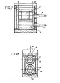
- Figures 7 and 8 show a variant of the rotary cutter of Figures 4 to 6.
- This embodiment differs from the previous one in that it uses four pairs of rollers 13 at the bottom instead of two, and four pairs of rollers 16 upstairs instead of two.
- Four guide lines have thus increased to eight. It is also possible to go up to twelve.
- This variant embodiment is justified whenever a high cutting power and greater cutting precision are sought.
- it allows the use of tools with a ceramic edge, thanks to its guiding precision.
- the flexions, detrimental in the prior art, are excessively reduced, the stressed section undergoing the pres cutting and counter-cutting sions being that corresponding to the diameter of the cylinders, much larger than that of the shafts 9, 10 which then have only a driving role and not a support.
- the shafts 9.10 therefore only serve to transmit the torques, the guiding of the cutting and anvil cylinders being ensured by trains of upper 16 and lower 13 rollers which always remain in place.
- rollers 16 and / or lower 13 In order to ensure perfect contact on a horizontal plane formed by the upper rollers 16 and / or lower 13, the rollers can be connected, two by two, by a hydraulic pipe in order to ensure a hydrostatic suspension.
Landscapes
- Engineering & Computer Science (AREA)
- Mechanical Engineering (AREA)
- Life Sciences & Earth Sciences (AREA)
- Forests & Forestry (AREA)
- Perforating, Stamping-Out Or Severing By Means Other Than Cutting (AREA)
- Control Of Cutting Processes (AREA)
- Manufacture Or Reproduction Of Printing Formes (AREA)
- Nonmetal Cutting Devices (AREA)
- Control And Other Processes For Unpacking Of Materials (AREA)
- Finish Polishing, Edge Sharpening, And Grinding By Specific Grinding Devices (AREA)
- Press Drives And Press Lines (AREA)
- Threshing Machine Elements (AREA)
Claims (6)
Priority Applications (1)
| Application Number | Priority Date | Filing Date | Title |
|---|---|---|---|
| AT87420071T ATE54869T1 (de) | 1986-03-13 | 1987-03-12 | Rollenschneidmaschine. |
Applications Claiming Priority (2)
| Application Number | Priority Date | Filing Date | Title |
|---|---|---|---|
| FR8604123 | 1986-03-13 | ||
| FR8604123A FR2595610A1 (fr) | 1986-03-13 | 1986-03-13 | Dispositif de decoupe rotative ou de refoulage pour produits plats |
Publications (2)
| Publication Number | Publication Date |
|---|---|
| EP0241388A1 EP0241388A1 (de) | 1987-10-14 |
| EP0241388B1 true EP0241388B1 (de) | 1990-07-25 |
Family
ID=9333419
Family Applications (1)
| Application Number | Title | Priority Date | Filing Date |
|---|---|---|---|
| EP87420071A Expired - Lifetime EP0241388B1 (de) | 1986-03-13 | 1987-03-12 | Rollenschneidmaschine |
Country Status (8)
| Country | Link |
|---|---|
| US (1) | US4770078A (de) |
| EP (1) | EP0241388B1 (de) |
| JP (1) | JPS62228395A (de) |
| KR (1) | KR870008635A (de) |
| AT (1) | ATE54869T1 (de) |
| DE (1) | DE3763879D1 (de) |
| ES (1) | ES2016644B3 (de) |
| FR (1) | FR2595610A1 (de) |
Cited By (1)
| Publication number | Priority date | Publication date | Assignee | Title |
|---|---|---|---|---|
| DE102011108954A1 (de) * | 2011-07-29 | 2013-01-31 | Gallus Druckmaschinen Gmbh | Vorrichtung zum Stanzen mit hydrostatischer Zylinderlagerung |
Families Citing this family (40)
| Publication number | Priority date | Publication date | Assignee | Title |
|---|---|---|---|---|
| US5138923A (en) * | 1988-11-18 | 1992-08-18 | Atlas Die, Inc. | Rotary die cutter |
| DE3924053A1 (de) * | 1989-07-21 | 1991-01-24 | Wilhelm Aichele | Vorrichtung zum rotationsschneiden von werkstoffbahnen |
| US5189935A (en) * | 1990-11-09 | 1993-03-02 | Richard Rosemann | Rotary cutting die assembly |
| WO1992008584A1 (en) * | 1990-11-09 | 1992-05-29 | Rosemann Richard R | Rotary cutting die assembly |
| US5156076A (en) * | 1991-05-21 | 1992-10-20 | Rosemann Richard R | Radially adjustable anvil roll assembly for a rotary die cutting press |
| US5946994A (en) * | 1991-12-11 | 1999-09-07 | Corropak, Inc. | Void fill material and process for manufacturing same |
| FR2684913B1 (fr) * | 1991-12-16 | 1996-02-02 | Umat | Appareil de decoupage rotatif. |
| US5348527A (en) | 1992-09-01 | 1994-09-20 | Rdp Marathon Inc. | Apparatus for cutting and stacking a multi-form web |
| US5417132A (en) * | 1993-01-19 | 1995-05-23 | Alan R. Pfaff | Rotary cutting dies |
| US5515757A (en) * | 1993-02-22 | 1996-05-14 | Corfine, Inc. | Rotary die cutters |
| US5598758A (en) * | 1993-07-22 | 1997-02-04 | Moore Business Forms, Inc. | Quick change cassette hole punch unit |
| US5467678A (en) * | 1993-08-25 | 1995-11-21 | Stollenwerk; Josef A. | Apparatus for automatically applying equalized pressure to a rotary cutting die |
| US6532854B2 (en) | 1994-01-21 | 2003-03-18 | Best Cutting Die Company | Cutting die clamping mechanism |
| US5697277A (en) * | 1994-05-17 | 1997-12-16 | Best Cutting Die Company | Multi use rotary die plate system |
| US5498148A (en) * | 1994-08-10 | 1996-03-12 | Recot, Inc. | Apparatus for forming sheets of material having a uniform thickness and cutting individual portions therefrom |
| US5553965A (en) * | 1995-02-14 | 1996-09-10 | Eastman Kodak Company | Constraint system for parallel cantilever shafts |
| US5498433A (en) * | 1995-04-18 | 1996-03-12 | Recot, Inc. | Apparatus and process for forming sheets of material having a uniform thickness |
| US6076444A (en) * | 1997-08-01 | 2000-06-20 | Best Cutting Die Company | Panel cutting apparatus with selectable matrices for vacuum and air |
| WO1999015299A1 (en) * | 1997-09-26 | 1999-04-01 | Eltron International, Inc. | Laminator printer |
| DE19834104A1 (de) * | 1998-07-29 | 2000-02-03 | Aichele Werkzeuge Gmbh & Co Kg | Schneidvorrichtung |
| EP1092516A1 (de) * | 1999-10-11 | 2001-04-18 | Gi Due S.r.l. | Vorrichtung zur Verstellung von Zylindern in Druckmaschinen, insbesondere für Rillvorrichtungen |
| DE10040024C1 (de) * | 2000-08-16 | 2002-07-25 | Aichele Werkzeuge Gmbh | Schneidvorrichtung |
| DE10044705C1 (de) * | 2000-09-09 | 2002-02-21 | Aichele Werkzeuge Gmbh | Rotationsschneidvorrichtung |
| DE10109933C1 (de) * | 2001-02-21 | 2002-08-22 | Aichele Werkzeuge Gmbh | Schneidvorrichtung und Schneidwerkzeug |
| US7299729B2 (en) | 2001-05-23 | 2007-11-27 | Cox William A | Rotary die module |
| US20030044481A1 (en) * | 2001-08-28 | 2003-03-06 | Beaudry Wallace J. | Cast ceramic edge or embossed surface for a cutting die |
| NL1024915C2 (nl) * | 2003-12-01 | 2005-06-06 | Jean Henry Robert Madern | Inrichting voor het aanbrengen van een snede, ril en dergelijke, omvattende een plaatvormig stelsel. |
| SE527886C2 (sv) * | 2004-07-02 | 2006-07-04 | Sandvik Intellectual Property | En rotationskniv, en stödvals och en rotationsknivsanordning |
| SE528038C2 (sv) * | 2004-07-02 | 2006-08-15 | Sandvik Intellectual Property | En luftdistributionsaggregat och en rotationsknivanordning försedd med ett dylikt lutfdistributionsaggregat |
| SE527838C2 (sv) * | 2004-07-02 | 2006-06-20 | Sandvik Intellectual Property | En rotationskniv och en rotationsknivanordning försedd med en dylik rotationskniv |
| US7849772B2 (en) * | 2005-04-07 | 2010-12-14 | Sandvik Intellectual Property Ab | Rotary cutting apparatus comprising a cutter drum and an anvil drum |
| SE529998C2 (sv) | 2005-04-07 | 2008-02-05 | Sandvik Intellectual Property | En stödvalstrumma och en stödvalsenhet för en roterbar skäranordning |
| DE102006044610B4 (de) * | 2006-09-19 | 2008-11-20 | WINKLER+DüNNEBIER AG | Vorrichtung zum Schneiden und/oder Prägen eines Zuschnittes oder einer Materialbahn |
| US8490912B2 (en) * | 2009-12-22 | 2013-07-23 | Jesus H. Sanchez | Arbor mounted disc adjusting apparatus |
| US8863627B2 (en) | 2011-03-18 | 2014-10-21 | The Procter & Gamble Company | Anvil roll system and method |
| DE102011108505A1 (de) * | 2011-07-25 | 2013-01-31 | Gallus Druckmaschinen Gmbh | Vorrichtung zum Stanzen mit einstellbarem Zylinderabstand |
| WO2015013798A1 (en) * | 2013-08-01 | 2015-02-05 | Eti Converting Equipment | Apparatus and method for cutting facestock |
| ITUB20153933A1 (it) * | 2015-09-28 | 2017-03-28 | Cartes S R L | Apparato per processare un materiale flessibile. |
| CN109015890A (zh) * | 2018-08-13 | 2018-12-18 | 深圳市博硕科技有限责任公司 | 一种提高圆刀单刀产能的工艺 |
| EP3915702A1 (de) | 2020-05-29 | 2021-12-01 | Proxicad S.r.l. | Rotierendes messer |
Family Cites Families (7)
| Publication number | Priority date | Publication date | Assignee | Title |
|---|---|---|---|---|
| DE487823C (de) * | 1929-05-18 | 1929-12-14 | Goebel A G | Vorrichtung zum Stuetzen von Messerwellen an Rollenschneidmaschinen |
| DE2917937B2 (de) * | 1979-05-04 | 1981-04-23 | Bielomatik Leuze Gmbh + Co, 7442 Neuffen | Querschneider mit wenigstens einer rotierenden Messerwalze |
| US4452116A (en) * | 1981-05-06 | 1984-06-05 | Preston Engravers, Inc. | Assembly for rotary die cutting utilizing a shaftless roll |
| US4553461A (en) * | 1982-10-12 | 1985-11-19 | Magna-Graphics Corporation | Rotary web processing apparatus |
| US4507996A (en) * | 1982-11-15 | 1985-04-02 | Preston Engravers, Inc. | Device for transferring and monitoring load to die roll |
| US4517873A (en) * | 1983-04-25 | 1985-05-21 | Wilson Manufacturing Company | Die cutting apparatus |
| US4641558A (en) * | 1985-08-16 | 1987-02-10 | B & H Manufacturing Company | Rotatable shaft assembly |
-
1986
- 1986-03-13 FR FR8604123A patent/FR2595610A1/fr active Pending
-
1987
- 1987-03-12 AT AT87420071T patent/ATE54869T1/de not_active IP Right Cessation
- 1987-03-12 KR KR870002210A patent/KR870008635A/ko not_active Withdrawn
- 1987-03-12 EP EP87420071A patent/EP0241388B1/de not_active Expired - Lifetime
- 1987-03-12 DE DE8787420071T patent/DE3763879D1/de not_active Expired - Lifetime
- 1987-03-12 JP JP62055444A patent/JPS62228395A/ja active Pending
- 1987-03-12 ES ES87420071T patent/ES2016644B3/es not_active Expired - Lifetime
- 1987-03-13 US US07/025,383 patent/US4770078A/en not_active Expired - Fee Related
Cited By (1)
| Publication number | Priority date | Publication date | Assignee | Title |
|---|---|---|---|---|
| DE102011108954A1 (de) * | 2011-07-29 | 2013-01-31 | Gallus Druckmaschinen Gmbh | Vorrichtung zum Stanzen mit hydrostatischer Zylinderlagerung |
Also Published As
| Publication number | Publication date |
|---|---|
| FR2595610A1 (fr) | 1987-09-18 |
| EP0241388A1 (de) | 1987-10-14 |
| DE3763879D1 (de) | 1990-08-30 |
| KR870008635A (ko) | 1987-10-19 |
| JPS62228395A (ja) | 1987-10-07 |
| US4770078A (en) | 1988-09-13 |
| ES2016644B3 (es) | 1990-11-16 |
| ATE54869T1 (de) | 1990-08-15 |
Similar Documents
| Publication | Publication Date | Title |
|---|---|---|
| EP0241388B1 (de) | Rollenschneidmaschine | |
| US4594928A (en) | Knife cylinder for working weblike material | |
| CH660464A5 (fr) | Machine de traitement d'une matiere en bande. | |
| FR2565520A1 (fr) | Dispositif de coupe automatique des tubes en carton et autres | |
| CH650968A5 (fr) | Machine pour decoupage par estampage. | |
| FR2620372A1 (fr) | Procede de stabilisation des conditions de decoupage d'un decoupoir rotatif et dispositif pour la mise en oeuvre de ce procede | |
| US4073326A (en) | Veneer-peeling machines | |
| EP0547954B1 (de) | Rotationsstanzvorrichtung | |
| EP0764505A1 (de) | Verfahren und Vorrichtung zur Einstellung des radialen Abstands zwischen zwei rotierenden Werkzeugen | |
| FR2513608A1 (fr) | Appareil de manutention de feuilles minces de materiau | |
| US7263921B2 (en) | Air distribution assembly and rotary cutting apparatus provided with such an air distribution assembly | |
| FR2556567A1 (fr) | Procede pour espacer et retourner deux longueurs de cigarette coaxiales sur une machine de montage de filtres | |
| FR2654168A1 (fr) | Element de bati logeant les portees d'arbres paralleles. | |
| EP1184142A3 (de) | Schneidkopf für mehrere Papierrollen | |
| FR2462241A1 (fr) | Dispositif de coupe a matrice rotative | |
| EP0662437B1 (de) | Vorrichtung zum Verbinden von Bändern aus weichem Material | |
| CN215825401U (zh) | 一种pet聚酯薄膜原料的分条切分装置 | |
| FR2662111A1 (fr) | Mecanisme pour le decoupage en continu de materiau en feuille en forme de bandes. | |
| BE504019A (de) | ||
| FR2504443A1 (fr) | Machine outil multidisques pour le decoupage et/ou le rainurage dotee d'au moins un arbre d'entrainement constitue de plusieurs troncons | |
| FR2588792A1 (fr) | Procede et dispositif d'usinage ou de controle sur site pour pieces rotatives | |
| FR2703621A1 (fr) | Système de cylindre presseur automatique à vitesse variable pour un dispositif rotatif de découpage à l'emporte-pièce. | |
| CN223545370U (zh) | 一种用于花草茶生产用的切料装置 | |
| FR2511636A1 (fr) | Massicot pour decouper un placage de bois pendant son defilement | |
| EP0599685A1 (de) | Vorrichtung zum Schneiden von Spalten durch ein Rohr |
Legal Events
| Date | Code | Title | Description |
|---|---|---|---|
| PUAI | Public reference made under article 153(3) epc to a published international application that has entered the european phase |
Free format text: ORIGINAL CODE: 0009012 |
|
| AK | Designated contracting states |
Kind code of ref document: A1 Designated state(s): AT BE CH DE ES FR GB IT LI NL SE |
|
| 17P | Request for examination filed |
Effective date: 19880402 |
|
| 17Q | First examination report despatched |
Effective date: 19890809 |
|
| GRAA | (expected) grant |
Free format text: ORIGINAL CODE: 0009210 |
|
| AK | Designated contracting states |
Kind code of ref document: B1 Designated state(s): AT BE CH DE ES FR GB IT LI NL SE |
|
| REF | Corresponds to: |
Ref document number: 54869 Country of ref document: AT Date of ref document: 19900815 Kind code of ref document: T |
|
| ITF | It: translation for a ep patent filed | ||
| GBT | Gb: translation of ep patent filed (gb section 77(6)(a)/1977) | ||
| REF | Corresponds to: |
Ref document number: 3763879 Country of ref document: DE Date of ref document: 19900830 |
|
| ITTA | It: last paid annual fee | ||
| PGFP | Annual fee paid to national office [announced via postgrant information from national office to epo] |
Ref country code: NL Payment date: 19910331 Year of fee payment: 5 |
|
| PGFP | Annual fee paid to national office [announced via postgrant information from national office to epo] |
Ref country code: FR Payment date: 19910412 Year of fee payment: 5 |
|
| PGFP | Annual fee paid to national office [announced via postgrant information from national office to epo] |
Ref country code: SE Payment date: 19910416 Year of fee payment: 5 |
|
| PGFP | Annual fee paid to national office [announced via postgrant information from national office to epo] |
Ref country code: ES Payment date: 19910422 Year of fee payment: 5 Ref country code: DE Payment date: 19910422 Year of fee payment: 5 |
|
| PGFP | Annual fee paid to national office [announced via postgrant information from national office to epo] |
Ref country code: GB Payment date: 19910423 Year of fee payment: 5 |
|
| PGFP | Annual fee paid to national office [announced via postgrant information from national office to epo] |
Ref country code: CH Payment date: 19910424 Year of fee payment: 5 Ref country code: BE Payment date: 19910424 Year of fee payment: 5 |
|
| PGFP | Annual fee paid to national office [announced via postgrant information from national office to epo] |
Ref country code: AT Payment date: 19910430 Year of fee payment: 5 |
|
| PLBE | No opposition filed within time limit |
Free format text: ORIGINAL CODE: 0009261 |
|
| STAA | Information on the status of an ep patent application or granted ep patent |
Free format text: STATUS: NO OPPOSITION FILED WITHIN TIME LIMIT |
|
| 26N | No opposition filed | ||
| PG25 | Lapsed in a contracting state [announced via postgrant information from national office to epo] |
Ref country code: GB Effective date: 19920312 Ref country code: AT Effective date: 19920312 |
|
| PG25 | Lapsed in a contracting state [announced via postgrant information from national office to epo] |
Ref country code: SE Effective date: 19920313 Ref country code: ES Free format text: LAPSE BECAUSE OF NON-PAYMENT OF DUE FEES Effective date: 19920313 |
|
| PG25 | Lapsed in a contracting state [announced via postgrant information from national office to epo] |
Ref country code: LI Effective date: 19920331 Ref country code: CH Effective date: 19920331 Ref country code: BE Effective date: 19920331 |
|
| BERE | Be: lapsed |
Owner name: GAUTIER JEAN Effective date: 19920331 |
|
| PG25 | Lapsed in a contracting state [announced via postgrant information from national office to epo] |
Ref country code: NL Effective date: 19921001 |
|
| GBPC | Gb: european patent ceased through non-payment of renewal fee | ||
| NLV4 | Nl: lapsed or anulled due to non-payment of the annual fee | ||
| PG25 | Lapsed in a contracting state [announced via postgrant information from national office to epo] |
Ref country code: FR Effective date: 19921130 |
|
| REG | Reference to a national code |
Ref country code: CH Ref legal event code: PL |
|
| PG25 | Lapsed in a contracting state [announced via postgrant information from national office to epo] |
Ref country code: DE Effective date: 19921201 |
|
| REG | Reference to a national code |
Ref country code: FR Ref legal event code: ST |
|
| EUG | Se: european patent has lapsed |
Ref document number: 87420071.0 Effective date: 19921005 |
|
| REG | Reference to a national code |
Ref country code: ES Ref legal event code: FD2A Effective date: 19990201 |
|
| PG25 | Lapsed in a contracting state [announced via postgrant information from national office to epo] |
Ref country code: IT Free format text: LAPSE BECAUSE OF NON-PAYMENT OF DUE FEES;WARNING: LAPSES OF ITALIAN PATENTS WITH EFFECTIVE DATE BEFORE 2007 MAY HAVE OCCURRED AT ANY TIME BEFORE 2007. THE CORRECT EFFECTIVE DATE MAY BE DIFFERENT FROM THE ONE RECORDED. Effective date: 20050312 |