EP0241101A1 - Système implantable cochléaire avec tests ou programmations psychologiques par l'intermédiaire des réponses cartographiques du malade prévues pour le codage - Google Patents
Système implantable cochléaire avec tests ou programmations psychologiques par l'intermédiaire des réponses cartographiques du malade prévues pour le codage Download PDFInfo
- Publication number
- EP0241101A1 EP0241101A1 EP87200716A EP87200716A EP0241101A1 EP 0241101 A1 EP0241101 A1 EP 0241101A1 EP 87200716 A EP87200716 A EP 87200716A EP 87200716 A EP87200716 A EP 87200716A EP 0241101 A1 EP0241101 A1 EP 0241101A1
- Authority
- EP
- European Patent Office
- Prior art keywords
- stimulation
- patient
- data
- encoding
- stimulator
- Prior art date
- Legal status (The legal status is an assumption and is not a legal conclusion. Google has not performed a legal analysis and makes no representation as to the accuracy of the status listed.)
- Granted
Links
Images


Classifications
-
- A—HUMAN NECESSITIES
- A61—MEDICAL OR VETERINARY SCIENCE; HYGIENE
- A61N—ELECTROTHERAPY; MAGNETOTHERAPY; RADIATION THERAPY; ULTRASOUND THERAPY
- A61N1/00—Electrotherapy; Circuits therefor
- A61N1/18—Applying electric currents by contact electrodes
- A61N1/32—Applying electric currents by contact electrodes alternating or intermittent currents
- A61N1/36—Applying electric currents by contact electrodes alternating or intermittent currents for stimulation
- A61N1/3605—Implantable neurostimulators for stimulating central or peripheral nerve system
- A61N1/36128—Control systems
- A61N1/36146—Control systems specified by the stimulation parameters
- A61N1/36182—Direction of the electrical field, e.g. with sleeve around stimulating electrode
- A61N1/36185—Selection of the electrode configuration
-
- A—HUMAN NECESSITIES
- A61—MEDICAL OR VETERINARY SCIENCE; HYGIENE
- A61N—ELECTROTHERAPY; MAGNETOTHERAPY; RADIATION THERAPY; ULTRASOUND THERAPY
- A61N1/00—Electrotherapy; Circuits therefor
- A61N1/18—Applying electric currents by contact electrodes
- A61N1/32—Applying electric currents by contact electrodes alternating or intermittent currents
- A61N1/36—Applying electric currents by contact electrodes alternating or intermittent currents for stimulation
- A61N1/36036—Applying electric currents by contact electrodes alternating or intermittent currents for stimulation of the outer, middle or inner ear
- A61N1/36038—Cochlear stimulation
- A61N1/36039—Cochlear stimulation fitting procedures
Definitions
- the invention described is primarily for a cochlear prosthesis, or implantable hearing prosthesis system, or bionic ear. That is, a system of components designed with the object of restoring some sensations of hearing to the profoundly deaf.
- the main object of the invention is to improve speech communication, but the importance of awareness of environmental sounds is also taken into account.
- the cochlear implant system seeks to bypass these hair cells in the cochlea by presenting electrical stimulation to the auditory nerve fibers directly, leading to the perception of sound in the brain.
- electrical stimulation to the auditory nerve fibers directly, leading to the perception of sound in the brain.
- the invention described herein comprises a multichannel eletrode implanted into the cochlea, connected to a multichannel implanted stimulator unit, which receives power and data from an externally powered wearable speech processor, wherein the speech processing strategy is based on known psychophysical phenomena, and is customized to each individual patient, by use of a diagnostic and programming unit.
- the cochlear chamber is about 35mm long when unrolled and is divided along almost its whole length by a partition. This partition is called the basilar membrane.
- the lower chamber is called the scala tympani. An opening at the remote end communicates between the upper and lower halves.
- the cochlea is filled with a fluid with a viscosity of about twice that of water.
- the scala tympani is provided with another piston or membrane called the round window which serves to take up the displacement of the fluid when the oval window is moved.
- the basilar membrane When the oval window is acoustically driven via the ossicles, the basilar membrane is displaced by the movement of fluid in the cochlea.
- the basilar membrane vibrates maximally at the remote end or apex for low frequencies and near the base or oval window for high frequencies.
- the displacement of the basilar membrane stimulates a collection of cells called the hair cells situated in a special structure on the basilar membrane. Movements of these hairs produce electrical discharges in fibers of the VIIIth nerve or auditory nerve.
- the nerve fibers from the hair cells closest to the round window convey information about high frequency sound
- fibers more apical convey information about low frequency sound. This is referred to as the tonotopic organization of nerve fibers in the cochlea.
- Hearing loss may be due to many causes, and is generally of two types.
- Conductive hearing loss is where the normal mechanical pathways for sound to reach the hair cells in the cochlea are impeded, for example by damage to the ossicles.
- Conduction hearing loss may often be helped by use of hearing aids, which amplify sound so that acoustic information does reach the cochlea.
- Some types of conductive hearing loss are also amenable to alleviation by surgical procedures.
- the stimulating electrode or electrodes is surgically placed in the scala tympani, in close proximity to the basilar membrane as shown in cross-section in Fig. 1B, and currents passed between the electrodes result in neural stimulation in groups of nerve fibers.
- the human speech production system consists of a number of resonant cavities, the oral and nasal cavities, which may be excited by air passing through the glottis or vocal chords, causing them to vibrate.
- the rate of vibration is heard as the pitch of the speaker's voice and varies between about 100 and 400 Hz.
- the pitch of female speakers is generally higher than that of male speakers.
- Speech is produced by the speaker exciting the vocal cords, and manipulating the acoustic cavities by movement of the tongue, lips and jaw to produce different sounds. Some sounds are produced with the vocal cords excited, and these are called voiced sounds. Other sounds are produced by other means, such as the passage of air between teeth and tongue, to produce unvoiced sounds. Thus the sound 'z' is a voiced sound, whereas 's' is an unvoiced sound; 'b' is a voiced sound, and 'p' is an unvoiced sound, etc.
- the speech signal can be analyzed in several ways.
- One useful analysis technique is spectral analysis, whereby the speech signal is analyzed in the frequency domain, and a spectrum is considered of amplitude (and phase) versus frequency. When the cavities to the speech production system are excited, a number of spectral peaks are produced, and the frequencies and relative amplitudes of these spectral peaks also vary with time.
- the number of spectral peaks ranges between about three and five and these peaks are called FORMANTS. These formants are numbered from the lowest frequency formant, conventionally called F1, to the highest frequency formants, and the voice pitch is conventionally referred to as Fo. Characteristic sounds of different vowels are produced by the speaker changing the shape of the oral and nasal cavities, which has the effect of changing the frequencies and relative intensities of these formants.
- the second formant (F2) is important for conveying vowel information.
- the vowel sounds 'oo' and 'ee' may be produced with identical voicing of the vocal cords, but will sound different due to different second formant characteristics.
- Psychiharmonic и is used here to refer to the study of the perceptions elicited in patients by electrical stimulation of the auditory nerve. For stimulation at rates between 100 and 400 pulses per second, a noise is perceived which changes pitch with stimulation rate. This is such a distinct sensation that it is possible to convey a melody to a patient by its variation.
- the pitch of sound perceptions due to electrical stimulation is also dependent upon frequency of stimulation, but the perceived pitch is not the same as the stimulation frequency.
- the highest pitch able to be perceived through the mechanism of changing stimulation rate alone is in the order of 1 kHz, and stimulation at rates above this maximum level will not produce any increase in frequency or pitch of the perceived sound.
- the perceived pitch depends upon electrode position. In multiple electrode systems, the perceptions due to stimulation at one electrode are not independent of the perceptions due to simultaneous stimulation of nearby electrodes. Also, the perceptual qualities of pitch, 'sharpness', and loudness are not independently variable with stimulation rate, electrode position, and stimulation amplitude.
- Some systems of cochlear implants in the prior art are arranged to stimulate a number of electrodes simultaneously in proportion to the energy in specific frequency bands, but this is done without reference to the perceptions due to stimulus current in nearby stimulating electrodes. The result is that there is interaction between the channels and the loudness is affected by this.
- an external speech processing unit converts the acoustic input into a signal suitable for transmission through the skin to an implanted receiver/ stimulator unit.
- These devices apply a continuously varying stimulus to the pair of electrodes, stimulating at least part of the population of auditory nerve fibers, and thus producing a hearing sensation.
- the stimulus signal generated from a given acoustic input is different for each of these systems, and while some degree of effectiveness has been demonstrated for each, performance has varied widely across systems and also for each system between patients. Because the design of these systems has evolved empirically, and has not been based on detailed psychophysical observations, it has not been possible to determine the cause of this variability. Consequently, it has not been possible to reduce it.
- the system described by Kissiah uses a set of analog filters to separate the acoustic signal into a number of frequency components, each having a predetermined frequency range within the audio spectrum. These analog signals are converted into digital pulse signals having a pulse rate equal to the frequency of the analog signal they represent, and the digital signals are used to stimulate the portion of the auditory nerve normally carrying the information in the same frequency range. Stimulation is accomplished by placing an array of spaced electrodes inside the cochlea.
- This system utilizes electrical stimulation at rates, say up to the limit of normal acoustic frequency range, say 10 ⁇ kHz, and independent operation of each electrode. Since the maximum rate of firing of any nerve fiber is limited by physiological mechanisms to one or two kHz, and there is little perceptual difference for electrical pulse rates above 800 Hz, it may be inappropriate to stimulate at the rates suggested. No consideration has been given to the interaction between the stimulus currents generated by different electrodes which in our experience may cause considerable, uncontrolled loudness variations, depending on the relative timing of stimulus presentations. Also, this system incorporates a percutaneous connector which has with it the associated risk of infection.
- the system proposed by Doyle limits the stimulation rate for any group of fibers to a rate which would allow any fiber to respond to sequential stimuli. It utilizes a plurality of transmission channels, with each channel sending a simple composite power/data signal to a bipolar pair of electrodes. Voltage source stimulation is used in a time multiplexed fashion similar to that subsequently used by Ricard and described below, and similar uncontrolled loudness variations will occur with the suggested independent stimulation of neighbouring pairs of electrodes. Further, the requirement for a number of transmission links equal to the number of electrode pairs prohibits the use of this type of system for more than a few electrodes.
- the system proposed by Ricard again utilizes a filter bank to analyze the acoustic signal and a single radio frequency link to transfer both power and data to the implanted receiver/stimulator, which presents a time-multiplexed output to sets of electrodes implanted in the cochlea.
- Monophasic voltage stimuli are used, with one electrode at a time being connected to a voltage source while the rest are connected to a common ground line.
- An attempt is made to isolate stimulus currents from one another by placing small pieces of silastic inside the scala, between electrodes.
- a common feature of all implanted receiver/stimulator units has been that the energy needed to power the implanted electronics (if any) and deliver the stimulus signal has been derived from an external power source, either directly from the data signal or from a separate power signal.
- the simplest and thus more reliable systems are those utilizing a single link, such as those described by Ricard and Hochmair.
- the Hochmair multichannel system uses FM data coding to transfer energy continuously, even during long intervals between stimuli.
- the energy efficiency of this approach is inherently less than that of approaches which transfer energy only when stimulation is imminent or actually in progress such as the Ricard system, and the system described herein.
- a start pulse providing enough energy to power the elecronics is sent at the start of every stimulation sequence.
- Each electrode is stimulated only once during each sequence, so for a series of stimuli to any single electrode the number of start bursts is equal to the number of stimuli.
- An improvement to this technique is to eliminate the need for the start pulse by minimizing the energy consumption of the electronics between stimuli (when no energy being received), allowing the electronics to still be in an active or powered state when the second and subsequent stimulus data sequences are received. This concept is utilized in the invention described herein.
- the system by Merzenich uses an interconnection pad between the implanted stimulator unit and the electrode array which enables him to select the electrode configuration to suit the patient's responses. This is done in a second surgical procedure after implantation.
- Other systems may use several implanted electrodes, and after testing, a choice is made of which electrode or electrodes are to be stimulated as a single channel.
- the primary aim of the invention to be described is to provide hearing sensations by electrical stimulation of the auditory nerve to alleviate the handicap in people suffering from profound sensironeural hearing loss, by means of an improved cochlear implant system.
- the aims and objects of this invention are: to provide a means where known and controllable electrical stimulation may be delivered to an electrode(s) of an electrode strip array positioned inside the cochlea; to provide a means satisfying the above object in a sufficiently small package that it is suitable for implantation inside the human body; to provide a means for transmitting power and information to the implanted cochlear stimulator across the skin without requiring a break in the skin; to provide a means for generating the information on which electrode to stimulate and at what amplitude on a stimulus to stimulus basis and derived from an acoustic signal; to provide a means for configuring the cochlear implant system to take account of each patient's unique characteristics, and to be able to perform this function without resort to extra surgery, or custom-made implantable components; and to design the cochlear implant system with the primary aim of improved speech communication, but also
- the invention operates efficiently with low power consumption and is sufficiently flexible in design to be capable of other (as yet undefined) speed processing strategies.
- This invention contemplates that several of the sub-systems will have separate utility in general in various other tissue stimulating prosthesis.
- the cochlear implant system of this invention shown in Figure 2 comprises several components.
- An Electrode Array 1 is implanted into the cochlea.
- the electrode comprises a number of rings or bands of platinum moulded with a flexible silastic carrier.
- the proximal 10 electrode bands are used for stiffening, and to act as an aid to surgical insertion.
- the electrode rings are about 0.05mm in thickness with a width of 0.3mm, and have outside diameters ranging from 0.6mm at the proximal end to about 0.4mm diameter at the distal end.
- the diameter of the rings changes smoothly so that the array is tapered over the distal 10mm or so.
- the rings are spaced on 0.75mm centers, over the distal 25mm of the electrode array, and all of the exposed outside area of the rings is used as active electrode area.
- Silastic material may be MDX4-4210, manufactured by Dow Corning.
- the 22 electrode wires pass in a cable 2 from the electrode to the Receiver - Stimulator Unit (RSU) 3 via a connector 4.
- RSU Receiver - Stimulator Unit
- the invention described is not limited to the use of this design of electrode array, and a number of alternative electrode designs as have been described in the prior art could be used, provided the wires from the active electrode sites could be attached to the connector. Reference may be made to the copending case Serial No. 402,227 for details on the connector.
- the RSU receives information and power from an external source through a tuned receiving coil 5 attached to the RSU and just beneath the skin.
- the RSU also provides electrical stimulating pulses to the electrode.
- the electrical connection between the electrode and the RSU is via a connector to allow the RSU to be replaced without requiring explantation of the electrode.
- the power, and data on which electrode to stimulate, and with intensity, is transmitted across the skin using an inductive link 6 operating at radio frequencies, from an external Wearable Speech Processor (WSP) 7.
- WSP Wearable Speech Processor
- the WSP picks up acoustic stimuli from a microphone 8 conveniently worn, and extracts from the signal, information which is used to determine stimulation electrode, rate and amplitude.
- the WSP has an Eraseable Programmable Read Only Memory (EPROM) which is programmed to suit each patient.
- EPROM Eraseable Programmable Read Only Memory
- the patient's response to electrical stimulation is tested some short time after implantation of the RSU, using the patient's WSP, and the results of these tests are used to set up the WSP for the patient's own particular requirements. This is done by connecting the WSP, via a connector and cables 9, to an Interface Unit (IU) 10.
- the IU is itself connected via a cable and connector 11 to a general purpose computer referred to as a Diagnostic and Programming Unit (DPU) 12.
- DPU Diagnostic and Programming Unit
- FIG. 3 A pictorial representation of the system used by the patient is shown in Fig. 3.
- the electrode array 20 is flexible and fits the shape of the cochlea as it is inserted along the basilar membrane separating the scala tympani from the remainder of the cochlea.
- the electrode array is connected via a silastic-covered cable 21 to the RSU 22. As pointed out in the previous Kuzma application Serial Number 402,227, this cable is specially designed to provide some stress relief to prevent wire fracture.
- the receiving coil for information and power is a single turn of multistrand platinum wire 23 which is transformer coupled to the implanted electronics in the RSU.
- An externally worn coil 24 is simply held against the head over the site of RSU implant by (for example) adhesive tape or a fixture, and is connected to the Speech Processor 29 by a coaxial cable 26.
- a conventional hearing aid microphone 27 is worn on the same ear as the transmitting coil, and a microphone lead 28 is contained in the same cable as the coil coaxial lead.
- Alternative microphone configurations are possible, including a microphone 33 mounted in the WSP case, or worn on a tie clasp or attached to the clothing, or attached to the fixture holding the transmitting coil.
- the cable is attached to the WSP by a demountable connector 32.
- the WSP is powered by conventionally available batteries (eg: 3 AA size cells shown as 30).
- the main aim of this invention is to provide improved speech communication to those people suffering from profound hearing loss, and thus the emphasis in design has been to optimize stimulation parameters for speech signals.
- environmental sounds for example telephones, doors, warning sirens, doorbells, etc.
- the 3rd and higher formants do not carry as much information as the 2nd.
- the most effective method of stimulation has been found to be to code the second formant on an appropriate electrode or site in the cochlea to provide the most important formant information.
- the amplitude of stimulation is derived from the amplitude of the second formant.
- the system described also provides prosodic information in the form of pulse rate. However, whereas other systems stimulate at the voice pitch rate, this system compresses the stimulation rate to the range 10 ⁇ 0 ⁇ to 250 ⁇ Hz, the range in which the greatest pitch discrimination from stimulation pulse rate is achieved.
- an additional factor is that only the top 10 ⁇ to 20 ⁇ dB of current acoustic stimulus level is used to determine stimulus amplitude. That is, instead of compressing the entire acoustic loudness range into the small range of electrical stimulation available, only the top part is used. In fact, the amplitude of the signal is internally represented by a 5 bit binary code, which provides only 25 dB of dynamic range.
- the speech processing strategy is:
- the system will still generate stimuli, but the stimulation rate and electrode position will be determined by the exact nature of the acoustic signal. For example, for sibilant consonants ('s'), the stimulation rate will be fairly fast, but not constant, and the electrode stimulated will be one which elicits a high frequency percept.
- a second alternative speech processing strategy has also been found to be useful in some patients, and we have discovered that it is advantageous to be able to offer a choice of strategies to patients.
- the second strategy is similar to the one mentioned above in that electrode position is encoded from second formant frequency.
- the stimulation rate is at the F1 or first formant frequency, and the stimulation amplitude is determined from the value of the peak of the acoustic signal at the time of the F1 peak. This has the advantage that the stimulation rate is faster, and elicits more natural sounding speech perceptions in some patients.
- the F1 signal is amplitude modulated and temporally patterned at the Fo rate, the patients also perceive the Fo or voice pitch which is useful for conveying prosodic information.
- the two alternative strategies and the method for generating them are later further discussed.
- Another speech processing strategy we have considered is to stimulate the patient at the rate of F1 extracted from an incoming speech signal, but to pattern the stimulation such that the stimuli are gated at the Fo rate.
- the cochlear implant system described herein is not limited to any one particular speech processing strategy. Indeed, it is one of the strengths of the invention that the implanted receiver unit is 'transparent' to the speech processing or sound encoding strategy adopted, and that future developments in this field will be able to be adapted without changes to the implant necessitating further surgery to the patient.
- the pulse which is used to electrically stimulate the cochlea is BIPHASIC, as shown in Fig. 4. That is, it comprises a period of negative current stimulation, followed by an equal period of positive current stimulation of equal amplitude, the two periods (known as phases phi 1 and phi 2), separated by a short period of no stimulation.
- Phi 1 and phi 2 may be in the range of 50 to 400 microseconds (typically 200 microseconds), and the intervening interval is typically about 50 microseconds.
- the amplitude of phi 1 and phi 2 their durations, and the duration of the intervening interval are determined by the information decoded from the signal transmitted by the speech processor.
- the stimulation circuitry is configured as a constant current source. This has the advantage compared to a constant voltage source that if the electrode impedance changes (as has often been observed) the delivered current to the electrode will remain unaltered over a large range of electrode impedances.
- the current may be varied from a few microamps to 2 mA, allowing a very large range of loudness percepts to be produced and large variations between patients to be accommodated.
- the system has the unique feature that the stimulus currents as delivered to the cochlea are known, as the system of generating the constant current stimulus is very well characterized, and has been designed to be substantially independent of many parameters (such as transmitting coil position) over a wide range.
- the stimulus generation circuitry in the RSU has been designed to operate in one of two modes.
- the first mode is referred to as 'multipolar' or 'common ground' stimulation.
- one electrode is selected to be the 'active' electrode, and all other electrodes operate as a common current source.
- phase 2 the connections are reversed so that the'active' electrode acts as the current source and the common electrodes act as a current sink.
- the choice of stimulus order is not determined by any limitations or restrictions in the circuit design, and either way may be chosen when implementing the circuit design.
- the second mode is 'bipolar' stimulation.
- stimulation is between two selected electrodes, let us say A and B.
- phase 1 current is sourced by A, and sunk by B.
- phase 2 current is sourced by B, and sunk by A, and no other electrodes play any part in stimulation.
- the RSU is configured so that any pair of electrodes may be selected for bipolar stimulation. Thus, there is great flexibility in choice of stimulation strategy.
- stimulation modes are not excluded by the system described herein.
- a multipolar or distributed ground system could be used where not all other electrodes act as a distributed ground, and any electrode could be selected at any time to be a current source, current sink, or inactive during either stimulation phase with suitable modification of the receiver-stimulator.
- the patient is allowed to recover for a short time, usually two weeks or so. After recovery, a number of psychophysical tests are carried out to determine the sensitivity and sharpness of perceptions elicited by stimulating the electrodes. This is done by an audiologist using the Diagnostic and Programming Unit ("DPU”), Interface Unit, and the patient's own speech processor.
- DPU Diagnostic and Programming Unit
- Interface Unit Interface Unit
- the testing may be done entirely under control of the audiologist, who can set a stimulus level, present the stimulus, and question the patient on his perceptions.
- Another technique we have found to be useful is to allow the patient to determine his own threshold stimulus level by adjusting a knob, slider or other patient operated control which can set the stimulus level.
- the patient can be instructed to set the stimulus level to threshold, or comfortable, at any level as required. This method allows much faster patient testing.
- MAP MAP
- This map contains data on which electrode to stimulate, and at what amplitude, for various combinations of F2 frequency and F2 amplitude, for the first speech processing strategy mentioned.
- the audiologist Before committing the information to the speech processor's memory however, the audiologist is able to talk to the patient using the patient's own speech processor via a temporary MAP stored in the DPU. It is possible to make changes to the MAP until it is decided that the information it contains will give the patient the best possible performance.
- the DPU is used to write the MAP into the speech processor's EPROM (eraseable, programmable, read-only-memory). The speech processor may then be unplugged from the DPU and operated independently from it.
- the patient locates the coil unit and microphone behind the ear in a position directly over the implanted package. A distance of no greater than 10 mm between the exterior and interior coils has been found to be satisfactory.
- the speech processor may be placed in TEST mode to deliver a constant stimulus to aid coil positioning. Once the coil has been correctly positioned, the speech processor may be placed in RUN and used in its normal mode.
- the WSP Weightable Speech Processor
- the WSP may be worn in the shirt pocket, holster or some other fitment to the clothing.
- the microphone is located on or near the ear and is of a highly directional type to allow the patient to focus his attention towards a particular speaker.
- a socket is provided into which a hand held microphone, radio or TV input may be plugged.
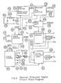
- FIG. 5 A diagrammatic representation of the Receiver/Stimulator, or cochlear implant, is shown in Fig. 5.
- Power and data is from a single externally worn coil 40 approximately 30 mm in diameter, and wound from about 8 to 15 turns of insulated copper wire. This coil is driven from the externally worn WSP, and the information to be transmitted is encoded by the WSP from the incoming speech signal.
- the power is received by a single turn platinum coil consisting of multiple strands of fine platinum wire wound together, and about 28 mm in diameter 41.
- Multistrand wire is used to improve the mechanical properties of the coil, and to reduce losses due to 'skin effect', which is significant in platinum at these frequencies.
- Both coils are "air" cored, that is, they do not make use of magnetic materials to function. This has an advantage over systems which do, in terms of bulk and weight savings.
- the transmitter coil has on the order to eight to fifteen turns to obtain the required inductance
- the receiver coil located inside the body has only one turn. This has the advantages that the single turn can be made very robust, insulation problems are greatly reduced and any electrical leakage to the surrounding tissues will be kept to a minimum due to the very low voltage present on the coil. The low voltage also has the effect that possible electrochemical effects on the coil itself will be kept to a minimum.
- the energy received by this coil is stepped up to a usable voltage level by a small transformer specially wound on a ferrite bead 44.
- the capacitor 45 in the secondary circuit of the transformer serves to tune the entire receiving circuit including the platinum coil and transformer.
- the transformer has a second function in that it isolates the receiver/stimulator circuit from the external coil. It this was not done, then the external coil could act as an extracochlear electrode, should there be an electrical current path to the surrounding tissue. Use of the transformer to electrically isolate the external coil allows the coil to be in direct contact with such tissue.
- the implantable package is encased in silicone rubber for protection, but electrical isolation and insulation does not depend upon the silicone rubber.
- the voltage induced in the transformer secondary is rectified by a silicon diode 46, and filtered by a power supply filter capacitor 48.
- the performance of the power coupling system has been found to give adequate power transfer over a range of about 10 mm when the transmitter and receiver coils are coaxial and a degree of lateral misalignment is possible at distances less than this.
- Some measure of overvoltage protection is provided by the zener diode 47.
- the coil/transformer is also connected through conductor 49 directly to the Receiver/Stimulator integrated circuit 50 for data recovery.
- An electrode array with platinum rings 52 (of which twenty-one are shown in Fig.5) is implanted surgically into the scala tympani (Fig. 1B) in contact with the basilar membrane of the cochlea.
- the rings are embedded in a tapered carrier shaped to fit loosely in the decreasing cross-section of the scala tympani, and is inserted, for example, through an opening made in the round window membrane.
- the distance that the electrode will be able to be inserted will be different for each patient, and depends upon each patient's physiology, anatomy and aetiology of deafness.
- the electrode array can be inserted a distance of 17 to 22mm.
- the electrode array is connected via a cable 53 to a connector 54 described in the previous Kuzma application. Connector 54 makes connection to the integrated circuit outputs 55 to provide stimulus currents of controlled amplitude and duration to the selected electrode.
- a separate rectifier diode and zener diode are used to provide power and protection for the implant.
- the rectifier diode and overvoltage protection may be incorporated in the receiver/stimulator IC itself. This has the obvious advantage of requiring fewer separate components inside the implant, with attendant possible reductions in size, and improvements in reliability.
- Vdd is the most positive voltage in the RSU
- Vss is the most negative, or ground.
- Vdd is 11 Volts, with respect to Vss which is taken as zero volts.
- the stimulus generation circuitry comprises a controllable current sink 60, where the current is determined by the data transmitted to the implant.
- Each of 22 electrodes e.g., electrode number 3 shown as 61
- switches are realized by enhancement mode MOS transistors, and are described in more detail in a later section.
- no electrodes are connected to any active circuitry, and thus electrode potentials are 'floating'. This is the condition when the implant is unpowered.
- electrode number 2 (designated the Reference electrode) is connected to the positive supply by switch 2a being closed
- electrode number 3 (designated the Active electrode) is connected to the current sink by switch 3b being closed.
- current flows out of electrode 2, through the cochlear structures, and into electrode 3.
- the voltage across the electrodes is dependent upon the electrode impedances, but the amount of charge delivered is precisely known. This is phase 1, or phi 1.
- bipolar electrodes In the bipolar configuration, two electrodes only are connected to the current sink and all other electrodes are left open circuited.
- adjacent electrodes are selected as Active and Reference, although any pair of electrodes may be selected as Active and Reference.
- bipolar electrodes may be separated by any desired distance, up to the length of the array. This capability provides the advantage of selecting an alternative electrode if the adjacent electrode is unsuitable, or the possibility of utilizing different stimulation strategies which may become identified in the future.
- the other mode of stimulation uses the 'common ground' or 'multipolar' electrode configuration, and is illustrated in Fig. 7.
- one electrode is stimulated against all the other electrodes which are connected together. That is, in phase 1 (Fig. 7A), electrode 2 is connected to the current sink, and all other electrodes connected to the positive supply. Thus current is sunk by electrode 2, and sourced by all other electrodes.
- the current distribution between the common ground electrodes is dependent upon a number of factors, including (predominantly) electrode impedance.
- phase 2 the connections are changed, as shown in Fig. 7B, so that the Active electrode is now connected to Vdd, and all other electrodes are connected to the current sink.
- the current in the Active electrode is the controlled biphasic current pulse.
- the other electrodes will have current waveforms which are also biphasic, but of lower amplitude, since the return current is shared between all other electrodes. A wider spread of current in the cochlea is thus produced by this configuration.
- Corrosion of electrodes can adversely affect the performance of the electrode, and may result in toxic corrosion products remaining in the cochlea. Polarization of all electrodes relative to the body is not theoretically possible because the system is closed. It can be seen that the maintenance of charge balance between electrodes is also done without the need for output capacitors, as mentioned previously.
- the advantage of having a number of possible modes of stimulation is that the most natural sounding percepts or those having the highest intelligibility may be selected once the patient has been implanted, rather than having to make this decision beforehand.
- the power/data link comprises two magnetically linked inductors, having a coefficient of coupling which depends on the placement of the external primary coil relative to the implanted secondary. Data is transmitted by controlling the number of cycles of excitation to the transmitter coil, which is heavily damped between bursts of pulses. At the receiver, the data signal energy is used for stimulation and also to provide power for the stimulator electronics.
- Digital data is encoded in the number of cycles in a burst, while analog functions are directly controlled by the duration of the burst.
- both the number of pulses detected and the received burst length depend on the coupling between coils. Tests using the coil configuration described below have shown a difference between transmitted and received pulse counts of one and occasionally two pulses, depending on coil position. Thus, a method of coding digital data is used which is tolerant to error counts of at least three pulses.
- the number N which is to be transmitted is encoded as the burst length 8N + 4 pulses, while the receiver divides the received pulse count by eight in its decoding process. This process is summarized in the following table for the first few integers:
- Fig. 8 shows the format of the data transmission to the implant.
- a data frame comprising six bursts of pulses at a pulse rate of 2.5 MHz is transmitted. This frequency of transmission was selected to allow presentation of stimuli in excess of 1 kHz, but it is understood that alternative embodiments using different frequencies would be within the spirit of this invention.
- the data coding described above provides a robust, self-clocking data format without requiring elaborate error checking. This is in contrast to other systems in which the data is digitally encoded, where the addition or loss of one or two pulses can produce a gross error.
- the choice of transmission frequency depends upon a number of factors. Firstly, in order to inductively couple power through body tissues for any reasonable distance, low frequencies (preferably less than a few tens of MHz) are desirable. At frequencies in excess of 10 MHz or so, it is not possible to efficiently transfer the power required. Low frequencies are typically used in pacemaker prior art for coupling information (and sometimes power) into a pacemaker encased in a metal package, and a frequency of 16 KHz may be used. At frequencies greater than about 50 KHz it is not possible to couple power into a metal container with acceptable efficiency, and receiver coils must be exercising to the container, as is used in this embodiment. Alternative packaging technologies which did not use metal would allow transfer of power to a receiver coil inside the package at higher frequencies.
- the minimum frequency which could be used is determined by the information transfer rate of the channel, at the times it is in use (i.e., in order to deliver a stimulus pulse with minimum delay).
- the technology which has been chosen for other reasons is CMOS, and contemporary CMOS technology has reliable operating frequencies of only a few MHz.
- CMOS complementary metal-oxide-semiconductor
- Sequential pulse bursts must be separated by at least a sufficient interval to allow the 'end of burst' to be detected: an interburst interval of 20 clock periods is used, and the system is designed to be tolerant of interburst intervals in excess of this time.
- This feature offers an advantage in that a constant time interval may be allocated for each stimulus frame, and thus there will be no jitter between stimulus pulses on different electrodes. Otherwise, encoded frames would be of different lengths, and thus the stimulus time relative to the start of the frame would vary with encoded data.
- the stimulator circuit has six possible states (S0 to S5), and the detection of the end of each burst is used to change the circuit state to the next sequential state. These states are also shown on Fig. 8.
- the SYNC burst is sent at the start of the frame to reset the system state to state S0.
- the received burst length must be less than 8 pulses, and a transmitted burst length of 4 pulses is preferred.
- the Active electrode is selected by the number decoded from the second burst. For example, electrode 5 is selected as the Active electrode if the number 5 is decoded from the second burst.
- the reference electrode may be selected from any of the remaining, i.e., not active, electrodes.
- the number decoded from the third, or mode select, burst is used to define the reference electrode as detailed herein. This number is described as the Stimulation Mode.
- Mode 1.
- the amplitude of the output current is determined by the duration of the amplitude burst.
- This burst has a minimum length of 16 pulses, which produces the maximum stimulus current of about 1 mA, and the amplitude is reduced in steps of about 3% for every 400 nS increase in burst duration. This is the increase in burst duration caused by adding a single cycle of that period in the burst.
- the relationship between perceptual loudness and stimulus amplitude is also logarithmic, allowing best use of the current steps available.
- the current amplitude is not coded numerically to eliminate the effects of coupling variations (like the electrode selection pulse burst), it can be seen that an error of one or two received pulses will result in only a small error in the stimulation current.
- the durations of the two phases of the stimulation pulse, phase 1 and phase 2 as shown in Fig. 4, are determined directly by the duration of the two stimulation bursts. Since each burst is an integral number of transmission cycles (each of duration 400nS for a 2.5 MHz transmission frequency), then the pulse duration can be adjusted in steps of 400nS. With the existing speech processor encoder, the maximum length of a stimulation burst is 1022 pulses, or 408.8 microseconds. However, there is nothing in the receiver circuitry itself to prevent use of longer bursts, if this is required. In normal use the durations of the two stimulus phases are equal, but they are set independently and may be different if so desired.
- the receiver/stimulator embodiment described below uses standard and conventional metal gate CMOS technology, with the circuits being realized using a gate array sometimes known as an uncommitted logic array available from AMI, TI, IMI, LSI Logic and Motorola.
- Logic arrays in general are available from a number of suppliers such as those listed. The particular logic array used is available from AWA Microelectronics and none of the suppliers listed.
- Many design features may also be realized using alternative technologies and techniques, for example, silicon gate technology and standard cell design philosophy, and such alternative embodiments are understood to be within the spirit of this invention.
- the gate array used in this embodiment comprises some 2000 n and p channel enhancement mode devices of similar dimensions in a central array, and additional devices located around the perimeter of the circuit.
- Vds Kn * ((Vgs - Vthn) ⁇ 2)
- Ids (Kn/2) * ((Vgs - Vthn) ⁇ 2)
- Ids (2*Kn) * ((Vgs - Vthn) ⁇ 2)
- the stimulator integrated circuit contains both digital and analog circuit functions.
- FIG. 9 A block diagram of the digital circuitry is shown in Fig. 9. Received signal energy from the tuned transformer 400, 401 is rectified by the diode 402 and used to power the circuit. A filter capacitor 403 maintains the supply voltage between data frames. The Burst Detector and Burst Clock Extraction circuit 404 is used to detect when a signal is present, and to recover a clock signal from the data signal 405, taken directly from the tuned circuit. The envelope detector output BURST 407 is asserted during signal bursts, while a threshold detector generates the CLOCK signal 406 from the unrectified signal input.
- the CLOCK signal is fed to the Prescaler and Sync Detector circuit 408 which has three functions. First, it carries out the divide by eight operation required to decode digital data and generate CLOCK8 409. Second, it asserts SYNC 412 for signal bursts of less than eight pulses, and third, it asserts BURST16 during the time for which a burst exceeds 16 clock cycles in length. BURST16 output 410 is used to control various analog functions as described below.
- the State Counter 422 At the heart of the circuit is the State Counter 422. It has six outputs S0 - S5 (423-427,420) which control the overall operation of the circuit. Only one output can be asserted at any time, and thus the system State is defined at any time as the output asserted at that time.
- State Counter In normal operation, the State Counter is left in State S5 between data frames, and the SYNC burst 412 generates a RESET 419 signal which sets the system State to S0.
- the State Counter is incremented through to S5 during the remainder of the frame by DATA signal 418, which is asserted at the end of every data (that is, not SYNC) signal burst.
- DATA and RESET are generated by the Error Detector circuit 415 which also detects if a DATA burst is received when in state S5, or if a SYNC burst occurs in a state other than S5. These are error conditions, and stimulation is inhibited through assertion of the INHIBIT signal 421.
- INHIBIT is also asserted under two other conditions related to the level of the supply voltage. These conditions are detected by analog sections of the circuit and signalled by assertion of VLOW 416 and VLOGIC 417. VLOW is asserted if the supply voltage at the start of the first stimulus phase is less than the voltage required for sufficient voltage compliance for the output current source, while VLOGIC is asserted if the supply voltage falls so low that there may be possible loss of data.
- INHIBIT is reset by a subsequent SYNC burst, received when in state S5.
- the Electrode Counter 428 is reset by the signal S5 420 and incremented during State S0 as described below. At the end of S0 its value is latched in the Active electrode latch 31, having 22 outputs A1-A22, shown as 430. During S1 the counter 428 may be further incremented and its output is used directly to select the Reference electrode outputs R1-R22, shown as 429.
- the Mode gate 413 applies the CLOCK8 signal 409 directly to the Electrode Counter during state S0, while during state S1 the initial CLOCK8 pulse is gated out.
- the signal BIPOLAR 414 is asserted if the Mode burst generates two or more CLOCK8 clock pulses.
- the counter used in the Electrode Counter circuit is cyclic, that is the next count after 22 is 1, thus enabling the Reference electrode number to be selected as lower than the Active electrode.
- Combinational logic is used to derive the signal STIM 411, which is asserted during both state S3 and state S4, provided that BURST16 is asserted.
- the Active and Reference electrode select signals AN and RN are asserted only if STIM is asserted and INHIBIT 421 is not asserted.
- FIG. 10 A block diagram of the analog circuit functions is shown in Fig. 10.
- the Supply Voltage Monitor 250 asserts the digital signal VLOW 416 and VLOGIC 417 under the conditions described above, while VHIGH 251 is asserted if the supply voltage exceeds a preset limit.
- VHIGH is used to control the Shunt Regulator circuit 252, and typically limits the maximum supply voltage to 2.0 volt above the VLOW value.
- the Reference Current Generator 253 produces the current Ir 261 which will vary from device to device as a result of manufacturing process variations.
- the Current Trim Network 254 is then used to set Iref to within 10 percent of its nominal value of 1 uA. Trimming is carried out by connecting the inputs A, B and C (255, 256, 257) to Vss or Vdd as required.
- the output stage of this current source 259 has an output impedance exceeding 1 Megohm.
- the current source is connected to the selected electrode through the selected Output Switching Networks (261 for example) during S3 and S4, as described below.
- the Burst Detector and Clock Extraction circuit is shown in Fig. 11.
- the unrectified input signal 281 is applied, through the standard input protection network 282, to the inverter formed by devices 283 and 284.
- the characteristics of these devices are chosen so that the inverter threshold is set to 70-80% of VDD, increasing tolerance to ringing in the receiver circuits at the end of bursts.
- Inverter 285 restores signal polarity, and the buffer 286 distributes the signal CLOCK 293, which is asserted when the input signal is above threshold.
- the inverter 287 turns on the P channel device 288 when CLOCK is asserted, forcing the node DET 290 high.
- the constant current sink 291 is used to discharge the nodal capacitance of DET to Vss in the absence of the signal CLOCK.
- the magnitude of this discharge current is selected to pull DET below the following Schmitt trigger 292 threshold if CLOCK is not asserted for more than 3-5 microseconds.
- the Schmitt trigger provides noise-free operation, even for this relatively slow transition of the DET node.
- the function of the Reference Current Generator is to provide a stable reference current without the need for any external components. It is also required that the current consumption is low, as this circuit is not disabled during state S5, when the circuit is unpowered.
- Devices 300 and 303 are both "long P" devices, and have similar K values, Klp, and threshold voltages Vthlp.
- the device 302 is an N channel peripheral device having its drain and P well connected to Vdd, its gate to Vss, and its source to device 303. So connected, it behaves as the bipolar npn device depicted in Fig. 12. The voltage drop across device 302 will be one Vbe.
- Vgs303 Vthlp + Vd
- Vbe is well defined by the manufacturing process, as are all K value ratios.
- the dominant cause of variability in Ir is thus the spread in absolute value of Klp to be expected during manufacture. Typically, this will vary across devices by up to 2:1 and it is this variability which required the use of the Current Trim Network.
- the value of Ir may be varied by either changing the relative K values for devices 301, 304, 305 or by changing the excess drive to device 300 from the value of one Vbe shown here.
- the current trim network 254 is shown in full in Figure 23a. It comprises a series of variable ratio current mirrors, where the ratios and thus the overall current transfer function of the network may be adjusted using external connections to Vss or Vdd.
- the table in Figure 23b illustrates the nominal transfer function as a function of the external trim connections. With this circuit no external components are required to trim the reference current source.
- the Programmable Current Source circuit is described in two parts: the Programmable Current Generator, and its associated Output Mirror.
- the circuit of the Programmable Current Generator is shown in Fig. 13 with circuit timing in Fig. 14, while the circuit and timing of the Output Mirror is shown in Fig. 15.
- the principles of operation of the Programmable Current Generator are easily understood by considering a large enhancement mode transistor which has its gate voltage adjusted such that it is operating in the subthreshold region, where the Ids to Vgs relationship is dominantly exponential.
- the Ids of this device is appropriately multiplied through the use of current mirrors to become the output current.
- a capacitor, called the SHC capacitor is connected between gate and source, and charged to the Vgs voltage.
- a current sink is now connected to discharge this capacitor. If the capacitor is discharged at a constant rate, then Vgs will decrease linearly and the output current will decrease exponentially with time. The final output current will be defined by the time for which the SHC capacitor is discharged.
- the large device described above is 334, and the capacitor SHC is connected between the node SHC and Vdd.
- Node SHC is discharged through the current mirror formed by devices 335, 336 and 337, provided that S2 and BURST16 are asserted, when TD is asserted and device 335 is turned off.
- the SHC capacitor is discharged only during state S2, BURST16 asserted.
- the SHC capacitor is charged during states S0, S1 and the duration of S2 for which BURST is not asserted.
- the combinational logic 339, 340, 342 and 346 asserts the signals TREF 343 and TREFN ((344), active low), turning on devices 332, 329 and 331.
- the current mirror 342, 321 generates the current Iref of approximately 5uA, and the feedback circuit comprising the current source 332 and the controlled current sink 330 charges the SHC capacitor such that Ids of 334 is equal to Iref.
- Device 333 is used to cascode device 334. The stability of the feedback loop is assured by the addition of resistor 348 to provide phase compensation.
- Iref 0 and device 324 is turned off, reducing current consumption of this area of circuitry to the leakage value.
- the P channel devices 338 and 341 limit the drift of the SHC node during this time.
- the output mirror (Fig.15) is enabled during S3 and S4 provided BURST16 is asserted. Under these conditions device 314 is turned off and the transmission gate 313 is turned on.
- a transmission gate is a p channel device connected in parallel with an n channel device--gate to gate, source to source, drain to drain.
- the current mirror formed by devices 310 and 311 (Fig. 15) defines the magnitude of the output current Io as four times the magnitude of the input current Ipr, while device 312 is used to cascode device 310.
- the output impedance of this current mirror is very high, even for large output currents, being in excess of 1 Megohm for an output current of 2 mA.
- the output node When the output stage is not enabled, the output node is clamped to Vdd by device 315.
- the initial conditions for this node are thus the same at the start of each output phase, improving the charge balance for equal amplitude, equal duration output pulses.
- Device 314 keeps device 312 turned off when the circuit is not enabled and the transmission gate 313 is open.
- the receiver/stimulator contains 22 Output Switching circuits, one for each electrode output.
- the schematic for one such circuit is shown in Fig. 16: it connects the output to Vdd if the signal S5 is asserted, and to Vdd or the Programmable Current Source, if selected by the control inputs An 368, Rn 369 and BIPOLAR 370.
- the signal S3 is used to control the multiplexer 362, directing the An input to the NOR gate 366 during state S3 and device 363 during state S4, and making the opposite connection for the output from NOR gate 361.
- the electrode is connected to VDD when S3 is asserted and to the current sink when S4 is asserted.
- WSP Wearable Speech Processor
- the function of the Wearable Speech Processor is to accept an incoming acoustic signal from a microphone, and after suitable processing, send the appropriate stimulation frames to the implanted Receiver Stimulator Unit in the patient.
- the WSP must be small, light, and low power, as it is intended that the WSP be worn on the body, e. g., in a shirt pocket, and be battery powered. Power consumption must be minimized to achieve longest possible time between change of battery, or recharging.
- the WSP must also be able to be configured for each patient's unique characteristics of psychophysics.
- a block diagram of the speech processor is shown in Fig. 17.
- a microphone 80 receives the acoustic input.
- This microphone may be a conventional hearing aid microphone, for example worn over the ear on a hook, or may be a higher quality studio type microphone, or the microphone may be replaced with another signal source such as the audio output from a television or radio. This flexibility of choice of input has advantages for the implant patient.
- the main aim of the WSP design is to provide the user with speech communication, and the stimulation strategy and description of terms reflects this. However, it is also important to provide the user with awareness of environmental sounds, and the stimulation strategy makes this possible also, although it is optimized for speech communications. In addition, it is possible to select the most appropriate strategy for each patient from a set of possibilities.
- the audio signal is amplified and processed by the WSP front end 81. From this, three signals are produced:
- ELSEL a voltage used to determine which electrode is to be selected for stimulation
- STAMP a voltage used to determine the amplitude of stimulation on the selected electrode.
- the START signal is used to initiate a single stimulus frame of pulse bursts by the Speech Processor Encoder 82 each time it occurs.
- the ELSEL and STAMP signals are used to determine stimulus parameters of electrode and stimulus level, according to which of the speech processing strategies previously described has been selected. An alternative speech processing strategy based on F1 is also possible using the invention described here.
- An 8 bit Analog to Digital Converter 83 converts the ELSEL and STAMP signals into numbers for use by the encoder.
- a two input analog multiplexer and sample and hold circuit 92 is under control of the encoder (for signal selection) and the ADC chip (for S/H control) so that the correct signal is presented to the ADC at the correct time.
- the encoder operates by way of a program stored in a UV erasable PROM 84, which also stores the map between F2 and electrode, and A2 and amplitude of stimulation, for each electrode. The stimulation amplitude is related to STAMP differently for each electrode, according to stimulation thresholds for that electrode.
- the five basic signals are: Fo the voicing or fundamental frequency Fo ⁇ the frequency translated Fo signal F2 a voltage proportional to F2 frequency A2 a voltage proportional to amplitude of the F2 signal F1 a pulse train at the frequency of the dominant spectral peak (F1) A the overall acoustic signal amplitude.
- Data from the front end are encoded by the encoder chip into the format shown in Figure 8, and described herein, and to the output stage 85, which is connected via a coaxial cable 86 to the transmitting coil 87.
- the transmitting coil is tuned to the correct frequency with a single capacitor 88 located at the coil.
- a connector 89 in the WSP allows connection to the Interface Unit, or IU, which is used during the testing of the patient, and allows the parameters to be programmed into the patient's map in the WSP.
- the WSP is powered from +5V and -5V supplies generated by a DC-DC Convertor 90 operating from batteries 91.
- Battery voltage may be in the range 3 - 7 volts, allowing a wide choice in number and style of batteries, including readily available primary cells, or rechargeable cells.
- the speech processor is constructed in a small case designed for easy carrying in a pocket, on a belt, or in a pouch under the clothing.
- the cable from the microphone and the coil on the ear attaches to the WSP by a connector for ease of use.
- Speech processor front end it is first necessary to be aware of the nature of the speech signal. Speech may be divided into two categories: voiced and unvoiced. Voiced speech is produced by a vibration of the glottis which provides an excitation source for a resonant system consisting of the oral and nasal cavities. A number of resonances (formants) are produced but of these the three lowest contain most of the information.
- Unvoiced speech does not use the glottis as an excitation source but rather a noise produced by the passage of air such as between the tongue and teeth (as in 's' and'th' and 'f'), or by explosive generation of sound pulses (such as in 'p' and 't'), or by the passage of air in the throat such as 'h').
- the WSP is designed to use one of two stimulation strategies, employing sets of three parameter estimates of the acoustic input, as follows:
- the perceived pitch with varying stimulus frequency is different to the stimulation frequency.
- This alternative speech processing strategy has the advantage of providing a faster stimulation rate which we believe may result in more naturally sounding speech for some patients.
- the stimulation rate is F1
- the amplitude of stimulation is encoded from overall amplitude of the acoustic input, for speech signals
- the Fo modulation of the speech signal is also perceived by the patient as a modulation of stimulus amplitude.
- this faster stimulation strategy may result in greater power consumption, with accompanying reduction in battery life.
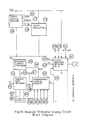
- Fig. 18 is block diagram of the WSP front end, with circuit element blocks identified. In general, each block is made in this embodiment with conventional circuit techniques, and anyone skilled in the art could create a circuit to reproduce the functions described.
- the choice of stimulation strategy is made in the speech processor by selection of circuit jumpers or switches 120 and 121.
- the microphone or other signal source 100 is amplified by a high gain low power microphone preamplifier 101, incorporating automatic gain control, or AGC.
- AGC automatic gain control
- the AGC allows the front end to operate without limiting, and operates in the conventional manner, with an AGC attack time of about 1 milliseconds, and an AGC decay time constant of about 220 milliseconds.
- the voltage controlling this gain is monitored and during periods of high gain (i.e., low signal) is stored by a minimum detector 114 and used as a reference level.
- the preamplifier has a maximum gain of 80dB, with a full gain bandwidth of 4.4 kHz. Pre-emphasis and deemphasis is possible to compensate for different microphones, as conventional directional miniature hearing aid microphones will require pre-emphasis of 6dB/octave above about 1kHz.
- Circuitry is included to generate a SQUELCH signal which is used to de-activate the encoder during periods of no signal.
- a comparator 116 When the incoming signal increases a preset amount above the level held in the minimum detector (deter strictlymined by the attentuator 115), a comparator 116 generates a logic level signal to enable the speech processor encoder. Otherwise it is assumed that background noise only is present and the encoder and output stage is disabled.
- the squelch circuit has a time out of about 200 milliseconds, such that the encoder is de-activated 0.2 seconds after the end of the last loud signal.
- the SQUELCH signal will enable the encoder during speech, and will allow up to 0.2 seconds delay between words before disabling the encoder.
- nonspeech signals such as environmental sounds like warnings, telephones, doors, etc., which are impulsive the SQUELCH circuit will also enable the encoder to produce stimuli.
- the squelch circuitry provides the advantage that battery life is conserved, as the encoder and output stage are active only when sufficient signal is present. This also has the advantage that the patient is not subjected to annoying or incomprehensible stimulation when used in environments with a high level of continuous background noise. However, in some circumstances, it is desirable to be aware of all background noise, and the patient has the ability to disable the operation of the squelch circuitry by a switch on the front panel of the WSP to continuously enable the encoder and output stage.
- the frequency of the second formant varies according to the utterance and the speaker, between about 800Hz and 3300 Hz.
- a high pass filter 102 is used. Because each successive formant is of lower amplitude than its predecessor, F1 values from some speakers could dominate the output of the filter if it were turned to a lower frequency.
- the output of the highpass filter is passed through a zero crossing detector 103 which has hysteresis so as to remove extraneous crossings produced by noise or the intrusion of F3 frequencies.
- the hysteresis amount is derived from the output of a peak detector 109 which sets the level appropriately.
- the magnitude of the hysteresis is about20%.
- the output of the zero crossing detector is input to a Frequency to Voltage Convertor 104 consisting of a monostable followed by a lowpass filter. Because the voltage produced by this circuit is subject to jitter a further hysteresis circuit 105 operates on the voltage representing the F2 frequency, with a hysteresis of about 14%.
- the final output of the F2 estimation circuitry is a voltage proportional to frequency at 1kHz per volt.
- the amplitude of the F2 signal after the high pass Filter is obtained via the peak detector 109.
- the output of a 2 pole linear phase lowpass filter with a corner frequency of 35 Hz provides a smoothed estimate of the formant amplitude A2.
- the periodic excitation of the resonant system of the vocal tract during a voiced utterance results in an amplitude modulated signal envelope.
- the excitation rate or voice pitch is derived from this envelope by full wave rectification using conventional full wave rectifier circuit built around an operational amplifier 106.
- the rectified signal has the DC level removed by AC coupling in a capacitor 107 which introduces a zero at about 70 Hz, and is then low pass filtered.
- This filter 108 is a 3 pole 200 Hz low pass filter in the Sallen and Keys configuration.
- Full wave rectification is used to double the "carrier" or resonance frequency thus easing the problem of separating the first formant frequency from the voice pitch.
- the resulting signal is converted to a voltage proportional to frequency with an identical circuit arrangement to the F2 path (except for the appropriate time constants) consisting of a zero crossing detector 110 with hysteresis level set by a peak detector 117.
- a frequency to voltage convertor 112 produces a voltage proportional to Fo frequency, at 130 Hz per volt.
- a voltage controlled oscillator 113 driven by this voltage then produces another frequency Fo ⁇ which is proportional to but not necessarily equal to Fo.
- the VCO has adjustable input voltage range, and also an adjustable offset to give a range of control over the linear conversion from Fo to Fo ⁇ .
- This Fo ⁇ frequency is used as the stimulation rate of a patient electrode, selected by F2 and stimulated at a level related to A2.
- a peak detector 118 following the microphone preamplifier follows peaks in the signal, which will be dominated by peaks at the F1 rate.
- the value of the peak is held in a Peak Hold circuit 119 and is used to determine stimulation amplitude.
- This circuit is realized with an operational amplifier charging a capacitor through a diode, with the capacitor voltage returned to the summing junction of the operational amplifier.
- the output of the operational amplifier is coupled with a capacitor and a resistor to the START input of the encoder, to start the encoder at the F1 rate, if this is selected.
- a START pulse will be produced everytime the input signal amplitude falls below the currently held peak value, and thus the encoder will stimulate at the F1 rate, at an amplitude determined by the value of the last peak in the signal.
- the two voltages, ELSEL and STAMP are made available to the ADC via a two input analog multiplexer and sample and hold circuit under control of the ADC and encoder, as shown in Fig. 17.
- Additional control circuitry allows the patient to operate a TEST function by way of the front panel switch on the WSP.
- the purpose of the TEST function is to generate comfortable level stimulus at a constant rate on the lowest frequency percept electrode. This electrode is usually the most apical electrode. This gives the patient a known and constant percept so that he may easily and simply adjust the coil position.
- the TEST function merely causes the input to the VCO 113 to be a constant, low level, and the output of the A2 path to be the maximum value.
- the TEST function is configured to impose a dummy load on the power supply, and light LED if sufficient battery power remains. This is a useful feature to warn the patient of battery failure.
- the speech processor encoder chip is used to generate pulse burst sequences which are subsequently transmitted via the output stage to the implantable receiver/stimulator in the patient.
- the pulse burst sequence is under the control of a program stored in an electronic memory device, such as an EPROM (e.g. 27C16), and the number of pulses in the variable parts of the pulse burst sequence is determined by the output of an ADC, and the program in memory.
- an EPROM e.g. 27C16
- the speech processor encoder chip is essentially a flexible, programmable pulse generator.
- the encoder chip is able to produce sequences of constant frequency pulses with the number of pulses and time between pulse bursts determined either by the internal program or in response to an externally applied analog signal (through an external ADC).
- the frequency of output pulses is determined by the frequency of the clock, and the system is designed to be able to work from DC to a frequency determined by the practical limits (about 10 MHz) of the CMOS technology in which the invention is embodied.
- the encoder chip is used to generate the fame of pulse bursts required for powering and controlling the implantable receiver stimulator.
- the format of these pulse burst frames is illustrated in Fig. 8.
- the encoder chip has been designed to be flexible, and will be useful in a number of applications where it is necessary to produce bursts of pulses.
- the encoder chip will be useful in applications where a different data encoding format is used, e.g., for use with future generations of receiver stimulation designs.
- Fig. 19 is a block diagram of the encoder, showing all functional blocks.
- the architecture of the encoder is similar to a conventional microprocessor in that there is an Address Bus, a Data Bus, Instruction Decode logic etc.
- ALU Arithmetic Logic Unit
- the encoder is not required to perform any arithmetic.
- the encoder also has similarities to a conventional state machine.
- the encoder is not designed to allow program branches or jumps dependent upon data generated in previous states, and the program running the encoder has each instruction executed exactly once from start to halt.
- the function of the encoder is to generate a number of pulses in a burst, dependent upon data presented to it on the data bus, and the contents of the instruction currently fetched from memory.
- the memory address bus has its contents originating from either the program counter (for instruction fetches, for example), internal registers (Electrode Latch, F2 Latch, and A2 Latch), or the data output from the ADC - or combinations of these.
- Circuitry exists in the encoder so that operation is enabled or disabled from external control lines shown symbolically as 130. Provided the encoder chip is ENABLED, each START pulse (shown symbolically as 131) initiates a sequence of pulse bursts called a frame, as defined before. START pulses occurring during a frame are ignored. This is important for a cochlear implant encoder since it is essential for the power/data signal format described above for all frames to be properly finished.
- Each burst of pulses is numbered sequentially from 0.
- the number of bursts in each frame is constant and fixed by the program in EPROM.
- the number of pulses in each burst may be fixed, or determined from the EPROM mapping between ADC value (an address) and the pulse count at that address.
- a fixed delay between bursts (8 clock times) is required to decode the next instruction, and load the pulse count for the next burst.
- the encoder is considered to exist in one of four states as follows:
- the operation of the encoder is that a START pulse initiates the first instruction fetch from memory at an address determined by the PROGRAM COUNTER 135.
- the instruction so fetched is loaded into the INSTRUCTION LATCH 134.
- the next state is the DATA state, where data from the memory is loaded into the DATA LATCH 139, and may also be loaded into other latches as needed, including the ELECTRODE LATCH 136, the F2 LATCH 137, or the A2 LATCH 138.
- the memory address from which the data is obtained is determined by the instruction, and various control signals (shown symbolically as 148) are decoded from the instruction in the INSTRUCTION DECODER 133.
- the next state is the COUNT state, where the 9 BIT BINARY COUNTER 142 counts up from its starting value to the value of the number in the DATA LATCH 139 and a ninth bit obtained from the current instruction.
- the internal clock signal may be made available to the OUTPUT pin, and is sent to the output stage, under control of the BURST COUNTER CONTROL LOGIC 143.
- a 9 BIT BINARY COMPARATOR 140 determines when the two numbers are equal, and causes the counting to stop and the next state of FETCH to be entered.
- the Encoder Chip continues through the states of FETCH, DATA and COUNT until the HALT instruction is fetched from memory, at which time further operation stops, and the encoder now exists in the HALT state.
- the input signals to the encoder are: START A signal generated externally by the WSP front end (i.e., Fo ⁇ ) at a rate determined by the incoming speech signal. ENABLE Enabling signal or signals (depending upon the embodiment) which allow the encoder to generate pulse frames in response to a START pulse.
- the Address Bus 146 is bidirectional, with the encoder putting out memory addresses, and the ADC data sometimes being applied to the address bus as well for mapping between F2, A2 and number of pulses. Five bits of the 8 ADC data bits are connected directly to the address bus (A7 to A3), and the other three bits are input to special pins which are internally connected to the address bus at the correct time (AD2-AD0).
- the data bus 147 is input to the encoder only, and comes from the memory.
- the memory is a UV Erasable PROM, but it is not a requirement that this type of memory be used exclusively.
- a random access memory is used within the Interface Unit of the Diagnostic and Programming Unit to emulate the PROM.
- Other memory technologies, such as EE-PROM could also be used.
- the outputs for the encoder are: OUTPUT: Bursts of output pulses sent to the RF output stage of the wearable speech processor.
- DAMP A signal asserted when pulses are not being output to allow damping of the RF output stage.
- DOUT An output line set/reset under program control (as described below). This line is included for expansion in the future, and may be particularly useful for example for adjustment of transmitted power level to conserve power, or expansion into more memory address space under program control.
- control signals bus are used to interface the encoder to the ADC and memory.
- CE 149 which is used as the Chip Enable for the Memory, and also as the Convert Start for the ADC.
- a separate Chip Enable from the encoder instead of enabling the memory the whole time allows the use of semiconductor memories whose power consumption is less when not enabled.
- the instruction fetched from the memory is an 8 bit word with the bit allocation as defined below where the functions of these bits is:
- This bit is directly output to a pin and is used to select one of two analog inputs to the analog to digital converter under program control. For interfacing convenience, the complement of this bit is also output to a pin.
- This bit is gated to the most significant bit of the address bus during the data cycle and allows data to be accessed from either half of the 2048 byte address space.
- the mapping strategy is discussed in further detail below.
- REGISTER SELECT These bits determine which register is to be gated on to the address bus during the DATA cycle. A detailed explanation is presented below.
- Burst Counter Control These bits are used to decode the mode of operation of the burst counter as described further below.
- This bit is used to add an extra bit input to the magnitude comparator to allow for 9 bit counting to extend the burst counter timing interval by an extra 256 pulses of burst counter clock.
- the data stored in the DATA LATCH is read from the memory during the DATA state.
- the location of this data in memory is determined by the contents of the address bus at the time.
- the Register Select bits in the control word are used to determine the source of the memory address in the DATA cycle. The bit assignment, and the use of each of the possibilities is described below.
- the register select bits may also be thought of as defining the instruction to be executed by the encoder from the set of 8 possible instructions.
- Fig. 20 graphically describes how the 1024 bytes of each half of the PROM address space is partitioned. The reader should note that this partitioning has been designed for maximum utilization of the available address space and this may explain some of the seemingly unusual bit allocations.
- RS2, RS1, and RS0 is shown after the instruction name.
- the program counter (which was incremented at the end of FETCH) is gated onto the address bus. Thus the DATA stored in the next byte in memory after the instruction is loaded into the DATA latch. The program counter is then incremented. This mode is used for generation of fixed duration delays or data bursts, as the number of pulses to be sent in the burst is stored in the ROM.
- This instruction is identical to the FIX instruction except that the DOUT output line is changed in state. NOTE: The DOUT line is always reset to 0 at the start of a frame.
- This instruction is the same as the FIX instruction except that a flip-flop called the A10 select flip-flop is toggled.
- This flip-flop is in the instruction decoder, and is used to select either the A10D signal or AD2 (the ADC input bit) for the mapping the inputs either to two halves of memory or extending the amplitude precision by one bit. See also notes on Fig. 20 for further explanation.
- the A10 select flip-flop is always reset to 0 at the start of a frame.
- F2ADC-ADC INPUT (F2 value) 111.
- the 8 bits output from the ADC is gated onto bits 2 to 9 of the address bus (MSB is A9) and bits 0 and 1 of the address bus are forced to logic 1.
- the data in this area of PROM is the map between F2 and electrode number.
- the 8 bit F2 value is also stored in the F2 LATCH 137 of 8 bits, from which it may be read again later.
- bits D7 to D2 of the DATA so generated from the PROM are stored in the ELECTRODE LATCH 136, offset, and in bit reversed order.
- This will encode the electrode number n, as 4*n + 2.
- the electrode number is encoded in the pulse burst to the implant by 8*n +4.
- the encoder chip design allows flexibility in encoding electrode number to take advantage of future designs which may utilize a different electrode encoding scheme, which would have advantages in terms of the maximum rate of stimulation.
- the most significant 5 bits of the ADC are gated onto bits A5-A9 of the address bus.
- the least significant 5 bits contain the contents of the electrode latch (Fig. 19) in bit reversed order.
- the electrode number must be constrained in the PROM to be no bigger than 1011 (23) to prevent intrusion of this part of the address space into the other address space. In the present design, this, therefore, limits the number of electrodes to 23.
- the electrode latch is of 6 bits in length, and the choice of which five of the six bits are placed onto the address bus depends on the choice of coding of electrode number as 4*n + 2 or 8*n + 4.
- An external control input to the encoder chip allows the user to choose which encoding strategy is to be used and thus which 5 of the 6 bits are to be placed onto the address bus at this time.
- the 6 most significant bits (A10 to A5) are stored in the internal A2 LATCH 138 for later re-use.
- the A2 latch data bit from A10 thus contains either AD2 (from ADC) or A10D from the current instruction.
- ADCE This is identical to ADCE (described above) except that the data previously stored in the A2 latch by an ADCE instruction is used instead of the ADC input. The data is not re-latched into the A2 latch but retained.
- the whole encoder chip exists in the HALT state between stimulation sequences.
- the HALT instruction also generates a control signal to read the ADC (RD). This guarantees the ADC will be ready to convert the data available on the first instruction to be executed in the frame so that ADC data, when first read in the frame will be the value at the start of the frame.
- the burst counter control bits determine whether clock pulses are transmitted during the burst count and whether the burst counter is reset at the end of a burst.
- BC0 is used to enable or disable the clock pulses to the output pin for the duration of the burst.
- BC1 is used to enable reset of the burst counter upon detection of the equality of the burst counter and the data in the data latch.
- the clock input to the burst counter is divided by two to allow a doubling of the time the clock is enabled to the output and the signals RG (reset gate) on ON are forced high.
- the choice of the source of the clock to the burst counter from either the divide by two circuitry 141 (Fig. 19) or directly from the clock generator 144 is done by an electronic switch whose state is set by control lines from the instruction decoder 133.
- the burst counter and control logic 143 section is used to generate pulses according to the number loaded into the DATA LATCH 139 in the DATA cycle.
- the BURST COUNTER 142 commences counting at the end of the DATA cycle and counts until the value in a bit binary counter 142 equals the number in the DATA LATCH 139 at which stage counting ceases and a new fetch cycle is initiated.
- the BURST COUNTER 142 is a 9 stage synchronous binary up counter.
- the control of the BURST COUNTER 142 is by the bits EXT, and BC0 and BC 1 in the current instruction.
- the EXT bit effectively extends the 8 bit data to 9 bits by adding an extra (most significant) bit.
- the state of BC0 determines whether or not the clock is enabled to the OUTPUT pin for the duration of the burst (i.e., an ON BURST or an OFF burst), BC1 determines whether or not the BURST COUNTER is reset at the end of the current burst.
- This facility eliminates the need for any arithmetic to be done inside the encoder chip.
- the input clock to the burst counter is pre-divided by two so that the time the counter is counting is exactly twice that when the normal clock is used.
- the number of output pulses can be doubled for the same number in the data latch.
- the equality of the 9 bit up counter and 8 bit data latch plus EXT bit from the current instruction is detected by a combinational logic network arranged as a 9 bit binary comparator 140.
- the clock signal is gated to the OUTPUT pin and the DAMP signal is asserted.
- the function of the internal timing and state generator 132 is to - generate power on reset of encoder chip; - generate the clock from the on chip crystal oscillator 144; - generate the initialization sequence which starts the program in EPROM when a START pulse is received if the chip is enabled.
- the power on reset is detected from a pin PORN 151 which will go high sometime after power is applied. This signal may be easily generated from a resistor and capacitor network.
- the function of the power on reset is to ensure that the encoder chip powers up to a known state.
- circuitry is included in the speech processor front end to prevent the encoder from operating if the power supply voltage is inadequate, as may occur towards the end of battery life. This is an important safety feature in the system to prevent spurious pulse frames being transmitted to the implant due to faulty operation of the logic circuits because of low supply voltage.
- a crystal oscillator is formed conventionally from a chain of an odd number of inverters. This is then gated into a divide by two circuit and the resulting clock is buffered heavily and distributed to the rest of the chip.
- the divider is only enabled while the encoder chip is running to conserve power. This is important because, in CMOS technology, practically all power consumption of the chip is derived from capacitive charging and discharging of nodal capacitance, whereas the DC power consumption is effectively zero.
- the divide by two circuit guarantees exactly equal mark/space ratio of the internal clock, and thus the external output signal, which is important for best efficiency of the output stage.
- the initializing sequencer is set up so that all enable inputs must be asserted to allow the START pulse to initiate operation of the encoder. After the program in memory has been started, further changes to START or the Enable inputs will have no effect until the current frame is complete (i.e., HALT instruction executed).
- the INSTRUCTION LATCH 134 is an 8 bit gated D latch which is loaded with the current instruction in the FETCH cycle.
- the contents of RS0-RS2 in the instruction latch are then decoded by combinational logic 133 and are used to determine the source of the address bus bits for obtaining the burst count as described above.
- the memory contains data on pulse burst length mapped from the ELSEL data and the STAMP data from the Speech Processor Front End.
- the INSTRUCTION DECODE LOGIC decodes the RS0-RS2 bits in the current instruction and sets signals to enable the appropriate latched data or ADC data to the ADDRESS BUS in the DATA cycle.
- the timing during the DATA cycle is such that the ADDRESS bus is set up by the various latch enable or ADC read signals prior to the time when the memory data is read into the DATA LATCH (and other latches as the case may be).
- the memory has about 2.5 clock cycles for the data to be stable (about luS), which should be adequate for even slow memories.
- a network of gates is used to decode the current instruction and assert the appropriate internal control signals for gating signals on to the Address Bus. Also, signals are generated for gating the contents of the Data Bus into the electrode latch, the F2 latch or the amplitude latch at the S2 time, depending on the instruction.
- Various internal control signals 148 are distributed to parts of the encoder circuit.
- the memory contains both the program and the data for the mapping between F2 and electrode number and electrode number combined with amplitude data to number of pulses (which will eventually control stimulus strength or duration).
- the address bus input to the memory may come from the following sources.
- Program Counter 2.
- ADC (8 bits)
- F2 latch (latched ADC data)
- Electrode latch plus most significant 5 bits of ADC 5. Amplitude latch plus electrode latch.
- the address space is mapped as shown in Fig. 20 and there are also gates to guarantee 1 states when using program counter, ADC input or F2 latch as input on some address bits.
- the F2 LATCH 137 (Fig. 19), the A2 LATCH 138 and the ELECTRODE LATCH 136 are all simple gated D-flip-flops, which are loaded in the DATA cycle if the appropriate condition codes are set up in the INSTRUCTION LATCH 134. These latch outputs are gated to the ADDRESS BUS for the whole of the DATA cycle by transmission gates if selected by the instruction decode logic.
- the PROGRAM COUNTER 135 is a 6 stage synchronous binary down counter which is decremented once each FETCH cycle, and once in the DATA cycle if fixed data is called for.
- the PROGRAM COUNTER is reset by an internal signal generated from a START pulse in the Internal Timing and State Generator, or by PORN.
- the most significant bit of the PROGRAM COUNTER is enabled to A10 during the FETCH cycle. In the DATA cycle, and A10D bit from the INSTRUCTION LATCH may be gated to A10 to enable either half memory mapping (except in FIX type instructions).
- PROGRAM COUNTER is a down counter is to reduce the possibility of ADC data intruding into the program space in memory and generating erroneous pulse bursts.
- the program always starts at address 7FF (HEX) (the highest address) and goes down to address 783 (HEX), then continues from address 3FF (HEX) and down to 383 (HEX) for a total program space of 64 bytes.
- This program space is adequate for even complicated pulse bursts, such as might be used for multiple electrode stimulation.
- the EPROM determines the most significant bit of the starting address of the program (i.e., A10) by strapping an externally available pin to either logic high or low.
- A10 the most significant bit of the starting address of the program
- the EPROM may be configured with two different programs in it, which may be chosen by the user. For example, two different programs may be established for noisy environments, and quiet environments, or for music or speech, etc.
- the starting address may be set to be either 7FF (Hex) or 3FF (Hex).
- the A10 bit may come from one of 3 sources:
- Logic is provided to select between these inputs at the appropriate time.
- the electrode latch is a 6 bit latch and the six bits of electrode number mapped from F2 input in response to the F2ADC instruction are stored in the latch.
- Either the upper 5 or lower 5 bits may be enabled to the address bus for an ADCE or A2L instruction by means of an array of multiplexors. This is to allow coding the electrode pulse burst as either 4N+2 OR 8n+4 (according to receiver design) without affecting EPROM addressing.
- the choice of which 5 bits are gated to the bus is made by strapping the externally available ELOPT pin to VCC or GND. This logic circuitry is not illustrated in Fig. 19 as it is only incidental to the operation of the encoder.
- the external address bus is driven by TRI-state bus drivers. Address bits 5, 6, 7, 8 and 9 are put to TRI-state level when the ADC is to be read as the ADC data is then gated to the Address Bus. These output pins are also fed back into the chip for storage in the internal latches as needed.
- TPS0, TPS1 and TPS2 are tied to logical 1, and the signals available to outputs are signals which are useful during normal operation of the encoder.
- all address bus pins may be set to TRI-state when the chip is in test mode (i.e., TPS0, TPS1, and TPS2 not all tied to logic 1), and one of the enable lines is asserted. This condition allows access to the address bus externally (e.g., to program the EPROM while in circuit).
- An example program for sending stimulus frames to the implant is shown below and will be used as the basis of the following discussion.
- This program will generate a train of pulse bursts according to the stimulus pulse frame definition shown in Figure 8. It should be understood that other programs could be used to generate the same stimulus frame, and may be used for different patients (e.g., to generate bipolar stimulation, or stimulus frames with different stimulus pulse lengths--phi 1 and phi2).
- This program consists of 11 steps. Each step will consist of a FETCH, DATA, and COUNT cycle. The detailed timing for the first step is given, and other steps will have similar timing.
- the program is initiated by the arrival of a START pulse from the speech processor front end, assuming the encoder is enabled.
- the START pulse causes the program counter to be reset to 11111, the burst counter is reset to 0, and starts the internal timing and state generator.
- the address bus contains 7FF, the address of the first instruction.
- the contents of this address (61 HEX) are strobed into the instruction latch during the first FETCH cycle.
- the program counter is decremented at the end of the FETCH cycle.
- the encoder and ADC is arranged so that the ADC conversion is initiated when the first instruction is fetched from memory. In this way, the ADC will be converting the value presented to its input at the same time as the encoder is executing the first instruction or so.
- the ADC used is an Analog Devices AD 7574, and has the desirable characteristic that further start convert signals are ignored until the previous data is read.
- the instruction is decoded as a fixed data instruction so the program counter is again enabled to the address bus.
- the contents of the next byte (at 7FB) in the program (04 HEX) are strobed into the data latch during the DATA cycle and the program counter is decremented again at the end of the DATA cycle.
- the burst counter control bits have been set by the contents of the instruction latch.
- the COUNT cycle begins, and the burst counter is enabled to count to 4 cycles. After 4 cycles, the equality of the burst counter and the data latch is detected, and a pulse is generated which initiates the next FETCH cycle. These four pulses are output to the OUTP pin and the burst counter is reset at the end. These four cycles transmitted to the receiver/stimulator are the Synch Burst referred to in Figure 8.
- step 2 the next instruction (3C HEX) is loaded from address 7F7(HEX) and the program counter is decremented.
- the data from the ADC is read.
- the ADC had a conversion started during the first instruction read by the same line which is used to chip enable the EPROM.
- the output of the ADC (8 bits) is enabled to the address bus bits 2 to 9 as shown in Fgure 20, and a number is read from the EPROM at the address so generated. This number will encode the electrode selected as 8*n + 4, and the number is output as a number of pulses.
- the electrode number is also stored in the ELECTRODE LATCH during the DATA cycle. The actual electrode selected depends upon the way that the ELSEL signal is mapped into electrode number for this particular patient. A detailed discussion on the mapping algorithms appears later in this disclosure.
- the number mapped from the F2 ADC input is output as a burst of pulses. At the end of this burst, the burst counter is not reset but is left in the state at which EQ was detected.
- the next instruction (40) is gated into the INSTRUCTION LATCH at the next FETCH.
- the constant data, 248 is gated into the DATA LATCH during the DATA cycle.
- the burst counter is enabled to continue counter from its end value to 248 at which time the counter is reset and the next instruction is fetched.
- the active electrode burst and subsequent inter-burst delay will take the time for 256 clock times, regardless of the actual number transmitted to the receiver/stimulator.
- Step 4 will result in the transmission of a 12 pulse burst which, in this example, will code the stimulation mode as 1, or multipolar. Other stimulation modes could be used. Step 4 is followed by a constant period of no output with the FIX instruction in Step 5 to provide the inter-burst delay.
- Step 6 the instruction is ADCE, and the 5 bits is the electrode latch are gated to Bits 4 to 0 of the address bus in bit reversed order as shown in Figure 20, and the 5 most significant bits of the ADC output are gated to bits 9 to 5 of the address bus.
- the data at the location in EPROM will then code the stimulus amplitude for the selected electrode at the value of the input signal (STAMP) represented by the number read from the ADC.
- Step 7 generates the interburst delay for the delay after the amplitude burst generated in Step 6.
- Steps 8, 9 and 10 generate the Phi 1 and Phi 2 times which, in this example, are shown to be 255 clock pulses long, although other Phi 1 and Phi 2 times could be chosen.
- the last instruction in Step 11 is a HALT instruction.
- This instruction causes the encoder to stop sending data, and also reads the ADC to make sure that the ADC is ready to begin a conversion on the first instruction fetch of the next pulse frame.
- the HALT instruction changes the state of the MUX bit so that the data presented to the ADC for the start of the next frame will be ELSEL.
- the MUX bit is caused to change value with Step 1 of the program, so that the next ADC conversion (for amplitude burst) will cause the conversion of the STAMP signal.
- the MUX bit operates a signal control line to select one of two analog signals to the ADC convertor as shown in Figure 17.
- the output stage is a Class D RF output stage using two enhancement mode power Field Effect Transistors (FETs), and is illustrated in Fig. 21.
- the signal 'OUTPUT' from the Encoder is level shifted from the logic levels of the encoder by the capacitor 200 and resistor 201.
- An N channel FET 204 selected to have a low ON resistance and a threshold of less than the logic swing is turned on by this level shifted signal.
- the drain of the FET is connected to the coil 207 worn by the patient by a coaxial cable 205.
- a capacitor 206 is selected to tune the coil. The value of the capacitor depends upon the length of the coaxial cable, as the parallel capacitance of the coaxial cable itself will contribute to the tuning capacitance.
- the other end of the coil is connected to the most positive supply.
- the N channel FET turns on, current is sunk through the coil.
- this FET turns off, the voltage across the coil rises sinusoidally to about 35 volts.
- the timing and tuning is arranged such that the voltage across the coil is thus typical of a Class D output stage, consisting of half sine wave shaped pulses, of about 35 Volt amplitude.
- a P channel enhancement mode FET 202 is in parallel with the coil via a silicon diode 203. This FET is turned on, and thus short circuits the coil, when the DAMP signal from the Encoder is asserted. The purpose of this is to damp out any residual oscillations in the tuned circuit system at the end of each burst so that the correct number of pulses will be received by the implanted receiver/stimulator.
- the design of the coil takes into account many factors, such as:
- the Diagnostic and Programming Unit (DPU) and Interface Unit (IU) are used together with a Wearable Speech Processor during the testing of the patient's psychophysics, and to set up the program and map in the WSP.
- the DPU is a conventional, off-the-shelf microcomputer system, to which software has been added.
- the IU is a specially designed device to interface between the DPU and the WSP.
- the DPU has available a communications interface which enables communication between it and the IU.
- a communications interface which enables communication between it and the IU.
- a 16 bit parallel communications link is used, but other formats or configurations could be used equally well, such as serial, or parallel with a different width of the data path.
- the WSP encoder works by fetching instructions from the EPROM in the WSP, and mapping the incoming formant data (F2 and A2) from the speech processor front end into the appropriate selection of electrode and amplitude to be sent to the implanted receiver stimulator.
- the algorithims for mapping are discussed in a subsequent section.
- the IU is a microprocessor based device with conventional structure.
- a processor 220 which is a Z80 in this embodiment but which could be any of a number of available processors, is the heart of the machine, and drives a Data Bus, Address Bus, and a number of control lines referred to as a Control Bus.
- System memory 221 comprises ROM and RAM, with necessary associated memory decoding and interfacing circuitry.
- a system event clock 222 is used for timing of events such as presentation of stimuli, or time of erasure of the PROM.
- a parallel communications interface 224 comprising 16 input and 16 output lines 225, with associated hand-shaking lines, allows communication with the DPU. The rest of the circuitry is used to control the WSP.
- the principal of control of the WSP is that the PROM in the WSP is disabled, and a SHADOW RAM 228 is made available to the encoder instead.
- This RAM appears to the WSP like the PROM, and is accessed through the Address, Data and Control Buses on the WSP from the Encoder mentioned in the previous section. However, this RAM may also be accessed by the IU processor, so that the IU can set up any programs or data in the shadow RAM, and thus control the operation of the WSP.
- Bus arbitration logic 231 is used to arbitrate between the WSP or the IU processor for access to the shadow RAM. It is possible to disable the address bus on the Encoder by using the test signal selectors mentioned in the section on the encoder.
- the WSP data bus is input only to the Encoder.
- the bus arbitration logic thus disables the encoder address bus, and disables the WSP PROM to make the shadow RAM available to the IU processor, by enabling an address bus switch 230 and a data bus switch 229.
- the Encoder itself is disabled to prevent generation of any stimulus frames which might contain spurious data and present unwanted stimuli to the patient.
- the WSP uses the time varying data from the speech processor front end to map and encode electrode number and stimulus amplitude.
- the IU it is necessary to be able to present stimuli which are also time varying. The way this is done is by use of an 8 bit latch 227 which is loaded from the IU processor.
- the encoder when variable data is required, the ADC value is input to the address bus, and the output data appears on the data bus from the PROM. The mapping between the variable ADC address, and the output data to be sent to the implant, is fixed in the PROM.
- the bus arbitration logic determines when an ADC read is to occur by decoding the WSP control lines. At this time, the WSP PROM, and the IU shadow RAM are disabled, and the 8 bit data latch is enabled to the data bus. Thus, the IU processor is able to update the data latch on a byte by byte basis to present variable data to the WSP encoder. In other words, the normal process of mapping variable ADC data from an address to data is bypassed.
- the IU is arranged so that the data in the data latch may be updated on a pulse burst by pulse burst basis, so that it is possible to send bursts with variable numbers of pulses to the implant, under control of the IU via the DPU.
- the communications protocol between the DPU and the IU is designed in the form of transactions which include hardware handshaking (embedded in the circuit design) and software handshaking, to enhance the reliability of data communications. This is important to make sure that erroneous data received by the IU from the DPU as a result of a hardware fault or 'glitch' in the system will not cause improper stimuli to be delivered to the patient.
- the normal stimulus protocol for patient testing is to use stimulus sequences where the amplitude of stimulus pulses delivered to the patient follows a trapezoidal waveform. In other words, starting from minimum possible stimulus, rising to the desired stimulus level in a known time and staying at that level for the required time, and then falling linearly to the minimum stimulus again.
- the IU processor In order to present this shape of stimulus envelope, the IU processor must be able to update the data latch very rapidly, at the same time as performing other tasks such as communications with the host DPU computer.
- the software inside the IU is structured to facilitate this, in that all input and output of communications, and also variable data to the encoder, is done via ring buffers in the conventional manner, with output to the data latch awarded the highest priority.
- the IU is able to generate the rising, falling and constant sections of the trapezoidal stimulus amplitude envelope with internal software in response to concise instructions from the DPU. This is an important feature as it allows the best economical use of the IU processor, without always tying up the DPU to calculate stimuli on a burst by burst basis. However, it is possible as well to present stimuli in any random fashion where all variable bursts may be set upon on a burst by burst basis from the DPU. This has an advantage in that hitherto unused or unthought of stimuli may be presented in the future if it is found to be useful for psychophysical testing or research.
- communication transactions between the DPU and IU are defined which include loading and reading the contents of the shadow RAM or WSP PROM; setting up stimuli with controllable time between stimuli, and definable contents of each burst in the frame; and various house-keeping functions such as PROM erasure, reset, and queue management.
- the process of patient testing is to present stimuli on specified electrodes at known stimulus levels, and question the patient for a response.
- the stimulus presentation is under control of the DPU, from instructions typed in at the keyboard by the user (e. g., an audiologist).
- the software in the DPU has been carefully written to make it difficult to present stimuli to the patient which may be uncomfortably loud, although the levels able to be presented by the implant are insufficient to be physiologically damaging.
- the patient may be asked to nominate thresholds, comfortable levels, and maximum comfortable levels on each or a subset of electrodes.
- Another test the patient may be asked to participate in is called pitch ranking, where the patient is asked to rank order psychophysically equally loud stimuli on different electrodes in order of pitch.
- This pitch ranking process is facilitated by the DPU software which generates random pairs of electrodes to be stimulated, to which the patient is required to nominate if the second is higher or lower in pitch than the first.
- a confusion matrix may be constructed, and the electrodes are then pitch ranked.
- Loudness Scaling An additional test is called Loudness Scaling, where the patient is asked to assign loudness weights to different stimuli levels on an electrode (or electrodes), so that the relationship between stimulus current and psychophysical loudness perceptions may be developed.
- the data from the tests is used to generate a map or translation table from VF2 to electrode number, and from A2 to amplitude.
- This translation process is done by the software in the DPU.
- One of the powerful features of the system is the ability to use any mapping algorithm between acoustic signal parameters and stimulation parameters merely by altering the software in the DPU.
- more stimulation strategies or mapping algorithms may be adopted to advantage.
- the mapping algorithms used in this embodiment are discussed in detail in a subsequent section.
- the map so generated must be programmed into the PROM in the patient's WSP. Thus it is necessary to be able to erase and reprogram the PROM in the patient's WSP.
- One way of doing this would be to have the operator (e.g., audiologist) remove the PROM from the speech processor, erase using conventional erasing devices, and program the PROM using conventional programming equipment.
- the operator e.g., audiologist
- circuitry is included in the IU to enable erasing and reprogramming of the EPROM while still plugged into the WSP.
- One of the most powerful features of the system described in this disclosure is the ability to configure the system on a patient to patient basis. After implantation, the patient is tested with the DPU/IU system to measure the patient's psychophysical characteristics. These characteristics are used to generate a map between acoustic signal parameters and stimulation parameters, which is stored in an EPROM in the patient's own wearable speech processor. In essence, the psychophysical variables are separated from the acoustic variables, with the link being through the map.
- two major parameters are of importance. These are the selection of electrode based on F2 frequency, or the way in which the electrodes are allocated portions of the frequency spectrum; and the way in which acoustic stimulus level (or acoustic loudness) is mapped into electrical stimulus level which results in perceptual loudness.
- the Output of the WSP front end produces an F2 signal which is a voltage linearly proportional to F2 frequency.
- F2 signal which is a voltage linearly proportional to F2 frequency.
- the second facet of mapping is the scaling of acoustic loudness to stimulation current.
- This is a particularly complicated subject, particularly in this embodiment where the subject of acoustic to psychophysical mapping is obscured by the AGC and Squelch characteristics of the WSP front end, and the nonlinear circuits used in the WSP front end to generate the STAMP signal.
- the DPU/IU system can be used to present stimuli of various current level to the patient on selected electrodes to determine the threshold level (i.e., the lowest level at which stimulation is reliably perceived), and maximum comfortable loudness, which is the maximum stimulus level which the patient can tolerate for sustained periods. The problem then becomes one of mapping the acoustic signal range as represented by the STAMP signal into this stimulation range.
- This map is to present stimuli to the patient at all possible levels between threshold and maximum comfortable loudness, and ask the patient to scale the perceived loudness, e.g., on an arbitrary scale between 1 and 100.
- This loudness scaling data may then be incorporated into the map so that acoustic loudness is correctly represented to the patient as perceived loudness.
- the software required in the DPU to perform this is quite straightforward.
- the exponent should be not C but C-16 since the programmable current generator circuit requires 16 pulses to start up, but this factor is ignored for the moment, as it represents a constant to be added to the number to be stored in the map.
- log(i) log(a) + C*log(b)
- the speech processor must relate the current level C, to the measured amplitude, A.
- L ⁇ the loudness of the input signal
- L the perceived loudness
- the system as described herein has provision for only 31 loudness levels to be mapped into the range of stimulus levels between threshold and maximum comfortable loudness level. Experiments have shown that this should be adequate. However, the system is not limited to varying stimulus level by varying stimulus current alone, as it is also possible to change the amount of delivered charge in the stimulus by altering the durations of Phi 1 and Phi 2. Different scaling algorithms, or different speech processing strategies as may be discovered in the future could use this mechanism of varying stimulus level to achieve finer control.
- the design of the encoder chip allows any or all of the bursts to be sent to the receiver/stimulator to be variable, and thus different mapping or encoding strategies may be easily developed.
- An additional part of the Diagnostic and Programming System not shown in the Figures is a means for acoustically monitoring the information output of the speech processor which is transmitted to the implantable receiver/stimulator.
- the purpose of such a device is as a troubleshooting aid, for when a patient reports a malfunction.
- the audiologist is able to apply the patient's own speech processor and coil to a simulator, and listen to an acoustic simulation of the stimulator output.
- the simulator includes a display of which electrode is being stimulated for each stimulation frame. This feature allows a visual interpretation of the extent of use of each electrode, and may assist the audiologist in best configuring the pitch ranking of the map to make best use of the available electrodes in the acoustic environment.
- such a simulator comprises a complete receiver/stimulator circuit as described in this invention.
- each output is connected via a light emitting diode to a dummy load such as a pair of headphones.
- a dummy load such as a pair of headphones.
Landscapes
- Health & Medical Sciences (AREA)
- Otolaryngology (AREA)
- Radiology & Medical Imaging (AREA)
- Engineering & Computer Science (AREA)
- Biomedical Technology (AREA)
- Nuclear Medicine, Radiotherapy & Molecular Imaging (AREA)
- Life Sciences & Earth Sciences (AREA)
- Animal Behavior & Ethology (AREA)
- General Health & Medical Sciences (AREA)
- Public Health (AREA)
- Veterinary Medicine (AREA)
- Neurosurgery (AREA)
- Neurology (AREA)
- Prostheses (AREA)
- Electrotherapy Devices (AREA)
Applications Claiming Priority (2)
| Application Number | Priority Date | Filing Date | Title |
|---|---|---|---|
| US483806 | 1983-04-11 | ||
| US06/483,806 US4532930A (en) | 1983-04-11 | 1983-04-11 | Cochlear implant system for an auditory prosthesis |
Related Parent Applications (1)
| Application Number | Title | Priority Date | Filing Date |
|---|---|---|---|
| EP84200496.2 Division | 1984-04-09 |
Publications (2)
| Publication Number | Publication Date |
|---|---|
| EP0241101A1 true EP0241101A1 (fr) | 1987-10-14 |
| EP0241101B1 EP0241101B1 (fr) | 1992-09-16 |
Family
ID=23921608
Family Applications (3)
| Application Number | Title | Priority Date | Filing Date |
|---|---|---|---|
| EP84200496A Expired - Lifetime EP0124930B1 (fr) | 1983-04-11 | 1984-04-09 | Système d'implant cochléaire pour une prothèse auditive |
| EP87200717A Expired - Lifetime EP0247649B1 (fr) | 1983-04-11 | 1984-04-09 | Dispositif de distribution et d'alimentation en courant pour une prothèse cochléaire implantable |
| EP87200716A Expired - Lifetime EP0241101B1 (fr) | 1983-04-11 | 1984-04-09 | Système implantable cochléaire avec tests ou programmations psychologiques par l'intermédiaire des réponses cartographiques du malade prévues pour le codage |
Family Applications Before (2)
| Application Number | Title | Priority Date | Filing Date |
|---|---|---|---|
| EP84200496A Expired - Lifetime EP0124930B1 (fr) | 1983-04-11 | 1984-04-09 | Système d'implant cochléaire pour une prothèse auditive |
| EP87200717A Expired - Lifetime EP0247649B1 (fr) | 1983-04-11 | 1984-04-09 | Dispositif de distribution et d'alimentation en courant pour une prothèse cochléaire implantable |
Country Status (6)
| Country | Link |
|---|---|
| US (1) | US4532930A (fr) |
| EP (3) | EP0124930B1 (fr) |
| JP (1) | JPS611200A (fr) |
| AU (3) | AU563754B2 (fr) |
| CA (1) | CA1212501A (fr) |
| DE (3) | DE3482548D1 (fr) |
Cited By (13)
| Publication number | Priority date | Publication date | Assignee | Title |
|---|---|---|---|---|
| US4972487A (en) * | 1988-03-30 | 1990-11-20 | Diphon Development Ab | Auditory prosthesis with datalogging capability |
| WO1994014376A1 (fr) * | 1992-12-22 | 1994-07-07 | Cochlear Pty. Ltd. | Appareil et systeme de telemetrie |
| WO1996006586A1 (fr) * | 1994-08-26 | 1996-03-07 | Fraunhofer-Gesellschaft zur Förderung der angewandten Forschung e.V. | Systeme d'implant de la cochlee |
| WO1997009012A1 (fr) * | 1995-09-05 | 1997-03-13 | Cochlear Pty. Limited | Multiplexeur percutane pour dispositifs therapeutiques |
| US5626629A (en) * | 1995-05-31 | 1997-05-06 | Advanced Bionics Corporation | Programming of a speech processor for an implantable cochlear stimulator |
| WO2001019304A1 (fr) * | 1999-09-16 | 2001-03-22 | Advanced Bionics N.V. | Implant cochleaire |
| US6289247B1 (en) | 1998-06-02 | 2001-09-11 | Advanced Bionics Corporation | Strategy selector for multichannel cochlear prosthesis |
| WO2002032501A1 (fr) * | 2000-10-19 | 2002-04-25 | Universite De Sherbrooke | Neurostimulateur programmable |
| WO2003032681A1 (fr) * | 2001-10-05 | 2003-04-17 | Oticon A/S | Procede de programmation d'un dispositif de communication, et dispositif de communication programmable |
| EP1666089A2 (fr) * | 1997-02-21 | 2006-06-07 | Intelligent Aquisition, LLC | Encodeur sensori-moteur avec des capacités d'apprentissage pour une neuroprothèse |
| US7292891B2 (en) | 2001-08-20 | 2007-11-06 | Advanced Bionics Corporation | BioNet for bilateral cochlear implant systems |
| US8588928B2 (en) | 2007-10-12 | 2013-11-19 | Cochlear Limited | Active electrode state control system with current compensation to reduce residual DC/LF voltage |
| US9008787B2 (en) | 2007-10-12 | 2015-04-14 | Cochlear Limited | Active electrode state control system |
Families Citing this family (426)
| Publication number | Priority date | Publication date | Assignee | Title |
|---|---|---|---|---|
| CA1226624A (fr) * | 1983-12-09 | 1987-09-08 | Minnesota Mining And Manufacturing Company | Systeme de transmission de signaux |
| AU569636B2 (en) * | 1984-09-07 | 1988-02-11 | University Of Melbourne, The | Bipolar paired pulse supplied prosthetic device |
| AU581936B2 (en) * | 1984-10-22 | 1989-03-09 | Cochlear Limited | Improvement in power transfer for implanted prostheses |
| DE3506721A1 (de) * | 1985-02-26 | 1986-08-28 | Hortmann GmbH, 7449 Neckartenzlingen | Uebertragungssystem fuer implantierte hoerprothesen |
| US4648403A (en) * | 1985-05-16 | 1987-03-10 | The Board Of Trustees Of The Leland Stanford Junior University | Method and apparatus for providing spread correction in a multi-channel cochlear prosthesis |
| US4606329A (en) * | 1985-05-22 | 1986-08-19 | Xomed, Inc. | Implantable electromagnetic middle-ear bone-conduction hearing aid device |
| EP0219380B1 (fr) * | 1985-09-12 | 1990-05-02 | Les Laboratoires MXM, S.A. | Appareil de stimulation neurale pour prothèse auditive |
| US4711243A (en) * | 1986-07-28 | 1987-12-08 | Cortronix, Inc. | Cortical hearing aid |
| NL8602043A (nl) * | 1986-08-08 | 1988-03-01 | Forelec N V | Werkwijze voor het verpakken van een implantaat, bijvoorbeeld een electronisch circuit, verpakking en implantaat. |
| US4823795A (en) * | 1987-03-13 | 1989-04-25 | Minnesota Mining And Manufacturing Company | Signal processor for and an auditory prosthesis having spectral to temporal transformation |
| US4813417A (en) * | 1987-03-13 | 1989-03-21 | Minnesota Mining And Manufacturing Company | Signal processor for and an auditory prosthesis utilizing channel dominance |
| US4905285A (en) * | 1987-04-03 | 1990-02-27 | American Telephone And Telegraph Company, At&T Bell Laboratories | Analysis arrangement based on a model of human neural responses |
| US4774933A (en) * | 1987-05-18 | 1988-10-04 | Xomed, Inc. | Method and apparatus for implanting hearing device |
| US4892108A (en) * | 1987-07-23 | 1990-01-09 | The Regents Of The University Of Michigan | Multi-channel extracochlear implant |
| US4975654A (en) * | 1989-03-10 | 1990-12-04 | Resound Corporation | Data signal discrimination method and apparatus |
| GB8914888D0 (en) * | 1989-06-29 | 1989-08-23 | Ferranti Creditphone | Burst mode transmitter/receiver unit |
| US5271397A (en) * | 1989-09-08 | 1993-12-21 | Cochlear Pty. Ltd. | Multi-peak speech processor |
| US5095904A (en) * | 1989-09-08 | 1992-03-17 | Cochlear Pty. Ltd. | Multi-peak speech procession |
| US5531774A (en) * | 1989-09-22 | 1996-07-02 | Alfred E. Mann Foundation For Scientific Research | Multichannel implantable cochlear stimulator having programmable bipolar, monopolar or multipolar electrode configurations |
| US5876425A (en) * | 1989-09-22 | 1999-03-02 | Advanced Bionics Corporation | Power control loop for implantable tissue stimulator |
| US5603726A (en) * | 1989-09-22 | 1997-02-18 | Alfred E. Mann Foundation For Scientific Research | Multichannel cochlear implant system including wearable speech processor |
| US5522865A (en) * | 1989-09-22 | 1996-06-04 | Alfred E. Mann Foundation For Scientific Research | Voltage/current control system for a human tissue stimulator |
| US5938691A (en) | 1989-09-22 | 1999-08-17 | Alfred E. Mann Foundation | Multichannel implantable cochlear stimulator |
| US5597380A (en) * | 1991-07-02 | 1997-01-28 | Cochlear Ltd. | Spectral maxima sound processor |
| AU675411B2 (en) * | 1991-09-27 | 1997-02-06 | Cochlear Limited | Self-curving cochlear electrode array |
| US5201903A (en) * | 1991-10-22 | 1993-04-13 | Pi (Medical) Corporation | Method of making a miniature multi-conductor electrical cable |
| US5524338A (en) * | 1991-10-22 | 1996-06-11 | Pi Medical Corporation | Method of making implantable microelectrode |
| WO1994000088A1 (fr) * | 1992-06-22 | 1994-01-06 | The University Of Melbourne | Ensemble d'electrodes disposees en courbe |
| JP3600239B2 (ja) * | 1993-07-01 | 2004-12-15 | ザ ユニバーシティ オブ メルボルン | 蝸牛移植具 |
| US7077822B1 (en) | 1994-02-09 | 2006-07-18 | The University Of Iowa Research Foundation | Stereotactic hypothalamic obesity probe |
| WO1995021591A1 (fr) * | 1994-02-09 | 1995-08-17 | University Of Iowa Research Foundation | Prothese neuronale destinee au cortex cerebral humain |
| AUPM883794A0 (en) * | 1994-10-17 | 1994-11-10 | University Of Melbourne, The | Multiple pulse stimulation |
| US5549658A (en) * | 1994-10-24 | 1996-08-27 | Advanced Bionics Corporation | Four-Channel cochlear system with a passive, non-hermetically sealed implant |
| US5584870A (en) * | 1995-03-09 | 1996-12-17 | Cochlear Ltd. | Implant ESD protection network |
| US5601617A (en) * | 1995-04-26 | 1997-02-11 | Advanced Bionics Corporation | Multichannel cochlear prosthesis with flexible control of stimulus waveforms |
| US6219580B1 (en) | 1995-04-26 | 2001-04-17 | Advanced Bionics Corporation | Multichannel cochlear prosthesis with flexible control of stimulus waveforms |
| US6109923A (en) * | 1995-05-24 | 2000-08-29 | Syracuase Language Systems | Method and apparatus for teaching prosodic features of speech |
| AUPN533195A0 (en) * | 1995-09-07 | 1995-10-05 | Cochlear Pty. Limited | Derived threshold and comfort level for auditory prostheses |
| USRE43519E1 (en) | 1995-11-13 | 2012-07-17 | Acacia Patent Acquisition Corporation | Electromagnetically protected hearing aids |
| US5640457A (en) * | 1995-11-13 | 1997-06-17 | Gnecco; Louis Thomas | Electromagnetically shielded hearing aid |
| AU4322596A (en) * | 1995-12-19 | 1997-07-14 | Cochlear Limited | Cochlear implant system with soft turn on electrodes |
| JP3561858B2 (ja) * | 1995-12-28 | 2004-09-02 | 務 大竹 | 医療用電極体を備えた医療器 |
| US5833714A (en) * | 1996-01-18 | 1998-11-10 | Loeb; Gerald E. | Cochlear electrode array employing tantalum metal |
| WO1997032629A1 (fr) * | 1996-03-06 | 1997-09-12 | Advanced Bionics Corporation | Stimulateur sans aimant implantable et emetteur exterieur et outils implantes servant a les aligner |
| JP3637497B2 (ja) * | 1996-03-13 | 2005-04-13 | メド―エル・エレクトロメディツィニシェ・ゲラーテ・ゲーエムベーハー | 硬化した蝸牛に埋め込む方法及び装置 |
| EP0959943B1 (fr) * | 1996-06-20 | 2004-03-17 | Advanced Bionics Corporation | Systeme d'implant cochleaire autoajustable |
| US5879283A (en) * | 1996-08-07 | 1999-03-09 | St. Croix Medical, Inc. | Implantable hearing system having multiple transducers |
| US5814095A (en) * | 1996-09-18 | 1998-09-29 | Implex Gmbh Spezialhorgerate | Implantable microphone and implantable hearing aids utilizing same |
| US5935166A (en) | 1996-11-25 | 1999-08-10 | St. Croix Medical, Inc. | Implantable hearing assistance device with remote electronics unit |
| US5735887A (en) * | 1996-12-10 | 1998-04-07 | Exonix Corporation | Closed-loop, RF-coupled implanted medical device |
| US5957958A (en) * | 1997-01-15 | 1999-09-28 | Advanced Bionics Corporation | Implantable electrode arrays |
| US6064913A (en) * | 1997-04-16 | 2000-05-16 | The University Of Melbourne | Multiple pulse stimulation |
| US6458157B1 (en) * | 1997-08-04 | 2002-10-01 | Suaning Gregg Joergen | Retinal stimulator |
| WO1999017585A1 (fr) | 1997-09-29 | 1999-04-08 | Cochlear Limited | Appareil et procede d'alarme publique pour implants cochleaires |
| US6353671B1 (en) * | 1998-02-05 | 2002-03-05 | Bioinstco Corp. | Signal processing circuit and method for increasing speech intelligibility |
| US6175767B1 (en) | 1998-04-01 | 2001-01-16 | James H. Doyle, Sr. | Multichannel implantable inner ear stimulator |
| US6351472B1 (en) * | 1998-04-30 | 2002-02-26 | Siemens Audiologische Technik Gmbh | Serial bidirectional data transmission method for hearing devices by means of signals of different pulsewidths |
| US6411854B1 (en) | 1998-04-30 | 2002-06-25 | Advanced Bionics Corporation | Implanted ceramic case with enhanced ceramic case strength |
| US6011993A (en) * | 1998-04-30 | 2000-01-04 | Advanced Bionics Corporation | Method of making implanted ceramic case with enhanced ceramic case strength |
| DE19827898C1 (de) * | 1998-06-23 | 1999-11-11 | Hans Leysieffer | Verfahren und Vorrichtung zur Versorgung eines teil- oder vollimplantierten aktiven Gerätes mit elektrischer Energie |
| WO2000000251A1 (fr) * | 1998-06-26 | 2000-01-06 | Advanced Bionics Corporation | Etage stimulus a courant de sortie programmable pour dispositif implantable |
| US6272382B1 (en) | 1998-07-31 | 2001-08-07 | Advanced Bionics Corporation | Fully implantable cochlear implant system |
| US6216040B1 (en) | 1998-08-31 | 2001-04-10 | Advanced Bionics Corporation | Implantable microphone system for use with cochlear implantable hearing aids |
| US6415185B1 (en) | 1998-09-04 | 2002-07-02 | Advanced Bionics Corporation | Objective programming and operation of a Cochlear implant based on measured evoked potentials that precede the stapedius reflex |
| JP2002527159A (ja) | 1998-10-13 | 2002-08-27 | コックレア リミティド | 組織刺激器のための高コンプライアンス出力段 |
| US6073050A (en) * | 1998-11-10 | 2000-06-06 | Advanced Bionics Corporation | Efficient integrated RF telemetry transmitter for use with implantable device |
| DE19859171C2 (de) | 1998-12-21 | 2000-11-09 | Implex Hear Tech Ag | Implantierbares Hörgerät mit Tinnitusmaskierer oder Noiser |
| US8260430B2 (en) | 2010-07-01 | 2012-09-04 | Cochlear Limited | Stimulation channel selection for a stimulating medical device |
| US7366315B2 (en) * | 1999-02-05 | 2008-04-29 | Hearworks Pty, Limited | Adaptive dynamic range optimization sound processor |
| AU772100B2 (en) | 1999-02-08 | 2004-04-08 | Cochlear Limited | Offset coils for radio frequency transcutaneous links |
| US6277148B1 (en) | 1999-02-11 | 2001-08-21 | Soundtec, Inc. | Middle ear magnet implant, attachment device and method, and test instrument and method |
| EP1083769B1 (fr) | 1999-02-16 | 2010-06-09 | Yugen Kaisha GM & M | Dispositif de conversion de la parole et procede correspondant |
| WO2000056393A1 (fr) * | 1999-03-24 | 2000-09-28 | Second Sight, Llc | Prothese retinienne de couleur pour restituer la vision des couleurs |
| AUPQ161099A0 (en) * | 1999-07-13 | 1999-08-05 | Cochlear Limited | Multirate cochlear stimulation strategy and apparatus |
| EP1351554B1 (fr) * | 1999-07-21 | 2011-02-16 | Med-El Elektromedizinische Geräte GmbH | Implant cochléaire à plusieurs canaux à télémesure de réaction neuronale |
| US6374143B1 (en) | 1999-08-18 | 2002-04-16 | Epic Biosonics, Inc. | Modiolar hugging electrode array |
| US6590986B1 (en) * | 1999-11-12 | 2003-07-08 | Siemens Hearing Instruments, Inc. | Patient-isolating programming interface for programming hearing aids |
| US6358281B1 (en) | 1999-11-29 | 2002-03-19 | Epic Biosonics Inc. | Totally implantable cochlear prosthesis |
| US7478108B2 (en) | 1999-12-06 | 2009-01-13 | Micro Strain, Inc. | Data collection using sensing units and separate control units with all power derived from the control units |
| US6436028B1 (en) | 1999-12-28 | 2002-08-20 | Soundtec, Inc. | Direct drive movement of body constituent |
| US6415186B1 (en) | 2000-01-14 | 2002-07-02 | Advanced Bionics Corporation | Active feed forward power control loop |
| AU2001251144A1 (en) * | 2000-03-31 | 2001-10-15 | Advanced Bionics Corporation | High contact count, sub-miniature, fully implantable cochlear prosthesis |
| DE10018334C1 (de) * | 2000-04-13 | 2002-02-28 | Implex Hear Tech Ag | Mindestens teilimplantierbares System zur Rehabilitation einer Hörstörung |
| US6636768B1 (en) | 2000-05-11 | 2003-10-21 | Advanced Bionics Corporation | Implantable mircophone system for use with cochlear implant devices |
| AU2001268142B2 (en) * | 2000-06-01 | 2006-05-18 | Otologics, Llc | Method and apparatus for measuring the performance of an implantable middle ear hearing aid, and the response of patient wearing such a hearing aid |
| US6456234B1 (en) | 2000-06-07 | 2002-09-24 | William J. Johnson | System and method for proactive content delivery by situation location |
| US8060389B2 (en) | 2000-06-07 | 2011-11-15 | Apple Inc. | System and method for anonymous location based services |
| US7289852B2 (en) * | 2000-06-16 | 2007-10-30 | Medtronic. Inc. | Implantable medical device configured for diagnostic emulation through serial communication |
| US6754533B1 (en) * | 2000-06-16 | 2004-06-22 | Medtronic, Inc. | Implantable medical device configured for diagnostic emulation |
| AUPQ820500A0 (en) * | 2000-06-19 | 2000-07-13 | Cochlear Limited | Travelling wave sound processor |
| EP1304017B1 (fr) * | 2000-06-30 | 2015-12-02 | Cochlear Limited | Implant cochleaire |
| US8285382B2 (en) * | 2000-08-21 | 2012-10-09 | Cochlear Limited | Determining stimulation signals for neural stimulation |
| US9008786B2 (en) * | 2000-08-21 | 2015-04-14 | Cochlear Limited | Determining stimulation signals for neural stimulation |
| AUPQ952800A0 (en) * | 2000-08-21 | 2000-09-14 | Cochlear Limited | Power efficient electrical stimulation |
| US7822478B2 (en) * | 2000-08-21 | 2010-10-26 | Cochlear Limited | Compressed neural coding |
| AUPR036600A0 (en) * | 2000-09-26 | 2000-10-19 | Cochlear Limited | Multiple battery management system |
| EP1255584B1 (fr) | 2000-10-04 | 2010-05-19 | Cochlear Limited | Combinaison d' un stylet et d'un manchon de redressement dans un appareil de stimulation implantable, en particulier dans un implant cochleaire |
| EP1326676A1 (fr) | 2000-10-04 | 2003-07-16 | Cochlear Limited | Ensemble d'electrodes pour implant cochleaire |
| US7269461B2 (en) * | 2000-10-11 | 2007-09-11 | Cochlear Limited | Double stylet insertion tool for a cochlear implant electrode array |
| US6745077B1 (en) | 2000-10-11 | 2004-06-01 | Advanced Bionics Corporation | Electronic impedance transformer for inductively-coupled load stabilization |
| EP1233810B1 (fr) | 2000-10-17 | 2010-04-21 | Cochlear Limited | Outil d'insertion pour groupement d'electrodes d'implant cochleaire |
| US9089450B2 (en) * | 2000-11-14 | 2015-07-28 | Cochlear Limited | Implantatable component having an accessible lumen and a drug release capsule for introduction into same |
| AUPR148400A0 (en) * | 2000-11-14 | 2000-12-07 | Cochlear Limited | Apparatus for delivery of pharmaceuticals to the cochlea |
| EP1339361B1 (fr) * | 2000-11-29 | 2011-08-03 | Cochlear Limited | Ensemble d'electrodes d'implant cochleaire prealablement recourbees |
| US6505076B2 (en) | 2000-12-08 | 2003-01-07 | Advanced Bionics Corporation | Water-resistant, wideband microphone subassembly |
| US6707920B2 (en) | 2000-12-12 | 2004-03-16 | Otologics Llc | Implantable hearing aid microphone |
| AUPR247601A0 (en) * | 2001-01-10 | 2001-02-01 | Cochlear Limited | Cochlear implant communicator |
| US6542777B1 (en) | 2001-01-19 | 2003-04-01 | Advanced Bionics Corporation | Spiral shield for a flexible high-Q implantable inductively coupled device |
| US8026637B2 (en) * | 2001-01-24 | 2011-09-27 | Cochlear Limited | Power supply having an auxiliary power cell |
| AUPR269301A0 (en) * | 2001-01-24 | 2001-02-22 | Cochlear Limited | Power supply for a cochlear implant |
| AUPR364601A0 (en) * | 2001-03-12 | 2001-04-12 | Cochlear Limited | Curved cochlear implant electrode array |
| EP1370205B1 (fr) * | 2001-03-19 | 2013-08-14 | Cochlear Limited | Systeme d'outil d'insertion pour reseau d'electrodes |
| AUPR408001A0 (en) * | 2001-03-29 | 2001-04-26 | Cochlear Limited | Laminated electrode for a cochlear implant |
| JP4290992B2 (ja) * | 2001-04-06 | 2009-07-08 | コクレア リミテッド | 骨内膜電極 |
| US7962226B2 (en) * | 2001-04-06 | 2011-06-14 | Cochlear Limited | Cochlear endosteal electrode carrier member |
| AUPR438601A0 (en) * | 2001-04-11 | 2001-05-17 | Cochlear Limited | Variable sensitivity control for a cochlear implant |
| WO2002082982A1 (fr) * | 2001-04-18 | 2002-10-24 | Cochlear Limited | Procede et appareil de mesure de reponses neuronales evoquees |
| WO2002089907A1 (fr) * | 2001-05-07 | 2002-11-14 | Cochlear Limited | Procede de fabrication de composants electroconducteurs |
| EP1256937B1 (fr) * | 2001-05-11 | 2006-11-02 | Sony France S.A. | Procédé et dispositif pour la reconnaissance d'émotions |
| AUPR520301A0 (en) * | 2001-05-23 | 2001-06-14 | Cochlear Limited | Transceiver coil for auditory prosthesis |
| AUPR551301A0 (en) * | 2001-06-06 | 2001-07-12 | Cochlear Limited | Monitor for auditory prosthesis |
| AUPR604801A0 (en) * | 2001-06-29 | 2001-07-26 | Cochlear Limited | Multi-electrode cochlear implant system with distributed electronics |
| US10576275B2 (en) * | 2001-07-06 | 2020-03-03 | Cochlear Limited | System and method for configuring an external device using operating parameters from an implanted device |
| GB2379121A (en) * | 2001-08-07 | 2003-02-26 | James Edward Aman | Hands-free kit with inductive link |
| US7155289B1 (en) | 2001-08-17 | 2006-12-26 | Advanced Bionics Corporation | Auto-referencing mixed mode phase locked loop for audio playback applications |
| US6537201B1 (en) | 2001-09-28 | 2003-03-25 | Otologics Llc | Implantable hearing aid with improved sealing |
| US6931141B2 (en) * | 2001-10-12 | 2005-08-16 | Gn Resound A/S | Hearing aid and a method for operating a hearing aid |
| US20100030130A1 (en) * | 2001-11-09 | 2010-02-04 | Cochlear Limited | Pharmaceutical intervention for modulation of neural plasticity |
| AUPR879201A0 (en) | 2001-11-09 | 2001-12-06 | Cochlear Limited | Subthreshold stimulation of a cochlea |
| US6620094B2 (en) | 2001-11-21 | 2003-09-16 | Otologics, Llc | Method and apparatus for audio input to implantable hearing aids |
| US7130694B1 (en) * | 2001-12-26 | 2006-10-31 | Advanced Bionics Corporation | Pulse skipping strategy |
| EP1468587A1 (fr) | 2002-01-02 | 2004-10-20 | Advanced Bionics Corporation | Ensemble microphone large bande faible bruit implantable |
| US7792586B2 (en) * | 2002-02-22 | 2010-09-07 | Cochlear Limited | Insertion device for an electrode array |
| AUPS081502A0 (en) * | 2002-02-28 | 2002-03-21 | Cochlear Limited | Connector for drug delivery system |
| US7818066B1 (en) | 2002-04-23 | 2010-10-19 | Advanced Bionics, Llc | Remote status and control device for a cochlear implant system |
| US7110822B1 (en) | 2002-04-23 | 2006-09-19 | Advanced Bionics Corporation | Remote status and control device for a cochlear implant system |
| AUPS274202A0 (en) * | 2002-06-03 | 2002-06-20 | Cochlear Limited | Clothing attachment device for a speech processor of a cochlear implant |
| US7519428B1 (en) | 2002-06-14 | 2009-04-14 | Advanced Bionics, Llc | Dual-range compliance voltage supply for a multi-channel stimulator |
| AUPS318202A0 (en) * | 2002-06-26 | 2002-07-18 | Cochlear Limited | Parametric fitting of a cochlear implant |
| AUPS322602A0 (en) * | 2002-06-28 | 2002-07-18 | Cochlear Limited | Coil and cable tester |
| AUPS322702A0 (en) * | 2002-06-28 | 2002-07-18 | Cochlear Limited | Cochlear implant electrode array |
| WO2004002570A1 (fr) * | 2002-06-28 | 2004-01-08 | Cochlear Limited | Dispositif a fibres optiques |
| US7254449B2 (en) * | 2002-07-31 | 2007-08-07 | Advanced Bionics Corp | Systems and methods for providing power to one or more implantable devices |
| US7016738B1 (en) | 2002-07-31 | 2006-03-21 | Advanced Bionics Corporation | Digitally controlled RF amplifier with wide dynamic range output |
| AU2002950754A0 (en) | 2002-08-09 | 2002-09-12 | Cochlear Limited | Mechanical design for a cochlear implant |
| AU2002950755A0 (en) * | 2002-08-09 | 2002-09-12 | Cochlear Limited | Fixation system for a cochlear implant |
| US7974700B1 (en) * | 2002-08-09 | 2011-07-05 | Cochlear Limited | Cochlear implant component having a unitary faceplate |
| US7248926B2 (en) * | 2002-08-30 | 2007-07-24 | Advanced Bionics Corporation | Status indicator for implantable systems |
| US7623929B1 (en) * | 2002-08-30 | 2009-11-24 | Advanced Bionics, Llc | Current sensing coil for cochlear implant data detection |
| AU2002951218A0 (en) * | 2002-09-04 | 2002-09-19 | Cochlear Limited | Method and apparatus for measurement of evoked neural response |
| WO2004024212A2 (fr) * | 2002-09-10 | 2004-03-25 | Vibrant Med-El Hearing Technology Gmbh | Dispositifs medicaux implantables a plusieurs transducteurs |
| US7319906B2 (en) * | 2002-09-19 | 2008-01-15 | Advanced Bionics Corporation | Cochlear implant electrode and method of making same |
| US7315763B2 (en) * | 2002-09-19 | 2008-01-01 | Advanced Bionics Corporation | Cochlear implant electrode and method of making same |
| US7349741B2 (en) * | 2002-10-11 | 2008-03-25 | Advanced Bionics, Llc | Cochlear implant sound processor with permanently integrated replenishable power source |
| US7127298B1 (en) | 2002-10-18 | 2006-10-24 | Advanced Bionics Corporation | Switched-matrix output for multi-channel implantable stimulator |
| AU2002952675A0 (en) * | 2002-11-07 | 2002-11-28 | Cochlear Limited | Clinical assistant for cochlear implant care |
| AT507045B1 (de) * | 2002-11-29 | 2010-04-15 | Cochlear Ltd | Implantierbare, gewebe-stimulierende vorrichtung |
| US7251530B1 (en) * | 2002-12-11 | 2007-07-31 | Advanced Bionics Corporation | Optimizing pitch and other speech stimuli allocation in a cochlear implant |
| DE10261682B4 (de) * | 2002-12-31 | 2014-07-17 | Gabriele Lisa Trinkel | System, Verfahren zur kontaktlosen Kommunikation mittels passiver, elektromechanischer Wandler |
| US6925332B2 (en) | 2003-02-03 | 2005-08-02 | The Children's Hospital Of Philadelphia | Methods for programming a neural prosthesis |
| AU2003900773A0 (en) * | 2003-02-21 | 2003-03-13 | Cochlear Limited | Telescopic array for a cochlear implant |
| US8229574B2 (en) * | 2003-02-21 | 2012-07-24 | Cochlear Limited | Telescopic electrode array |
| US8255059B2 (en) | 2003-03-11 | 2012-08-28 | Cochlear Limited | Using a genetic algorithm to fit a medical implant system to a patient |
| US6879860B2 (en) * | 2003-03-11 | 2005-04-12 | Gregory Howard Wakefield | Cochlear implant MAP optimization with use of a genetic algorithm |
| US8355794B2 (en) * | 2003-03-11 | 2013-01-15 | Cochlear Limited | Using a genetic algorithm in mixed mode device |
| AU2003901730A0 (en) * | 2003-04-11 | 2003-05-01 | Cochlear Limited | Power management system |
| AU2003901852A0 (en) | 2003-04-16 | 2003-05-01 | Cochlear Limited | Cochlear electrode array |
| AU2003901867A0 (en) | 2003-04-17 | 2003-05-08 | Cochlear Limited | Osseointegration fixation system for an implant |
| US8270647B2 (en) | 2003-05-08 | 2012-09-18 | Advanced Bionics, Llc | Modular speech processor headpiece |
| US7599508B1 (en) | 2003-05-08 | 2009-10-06 | Advanced Bionics, Llc | Listening device cap |
| US8811643B2 (en) | 2003-05-08 | 2014-08-19 | Advanced Bionics | Integrated cochlear implant headpiece |
| US7317944B1 (en) | 2003-07-08 | 2008-01-08 | Advanced Bionics Corporation | System and method for using a multi-contact electrode to stimulate the cochlear nerve or other body tissue |
| AU2003903532A0 (en) * | 2003-07-09 | 2003-07-24 | Cochlear Limited | Conductive elements |
| AU2003903576A0 (en) * | 2003-07-11 | 2003-07-24 | Cochlear Limited | Audio path diagnostics |
| AU2003903579A0 (en) * | 2003-07-11 | 2003-07-24 | Cochlear Limited | Three wire headset |
| AU2003904085A0 (en) * | 2003-08-04 | 2003-08-21 | Cochlear Limited | Magnetic on/off switch for speech processor |
| AU2003904086A0 (en) * | 2003-08-04 | 2003-08-21 | Cochlear Limited | Implant battery short circuit protection |
| AU2003904139A0 (en) * | 2003-08-07 | 2003-08-21 | Cochlear Limited | Miniature switches |
| US20070239227A1 (en) * | 2003-08-15 | 2007-10-11 | Fridman Gene Y | Frequency modulated stimulation strategy for cochlear implant system |
| US7529587B2 (en) * | 2003-10-13 | 2009-05-05 | Cochlear Limited | External speech processor unit for an auditory prosthesis |
| US7556597B2 (en) * | 2003-11-07 | 2009-07-07 | Otologics, Llc | Active vibration attenuation for implantable microphone |
| US7204799B2 (en) * | 2003-11-07 | 2007-04-17 | Otologics, Llc | Microphone optimized for implant use |
| US7292892B2 (en) * | 2003-11-21 | 2007-11-06 | Advanced Bionics Corporation | Methods and systems for fitting a cochlear implant to a patient |
| US7167754B1 (en) | 2003-12-17 | 2007-01-23 | Advanced Bionics Corporation | Low power inverted alterphasic stimulation in a cochlear implant |
| US8023673B2 (en) * | 2004-09-28 | 2011-09-20 | Hearworks Pty. Limited | Pitch perception in an auditory prosthesis |
| US7534127B2 (en) * | 2004-01-05 | 2009-05-19 | Cochlear Limited | Implantable connector |
| US8577473B2 (en) * | 2004-03-08 | 2013-11-05 | Med-El Elektromedizinische Geraete Gmbh | Cochlear implant stimulation with low frequency channel privilege |
| US7333858B2 (en) * | 2004-03-31 | 2008-02-19 | Cochlear Limited | Pulse burst electrical stimulation of nerve or tissue fibers |
| US7840020B1 (en) | 2004-04-01 | 2010-11-23 | Otologics, Llc | Low acceleration sensitivity microphone |
| US7214179B2 (en) * | 2004-04-01 | 2007-05-08 | Otologics, Llc | Low acceleration sensitivity microphone |
| US20060241753A1 (en) * | 2005-04-25 | 2006-10-26 | Suaning Gregg J | Electrode multiplexing method for retinal prosthesis |
| US8660658B2 (en) | 2004-05-05 | 2014-02-25 | Advanced Bionics Ag | Speech processor cases |
| US8068914B1 (en) * | 2004-05-05 | 2011-11-29 | Advanced Bionics, Llc | Speech processor cases |
| US7412288B2 (en) * | 2004-05-10 | 2008-08-12 | Phonak Ag | Text to speech conversion in hearing systems |
| US8244365B2 (en) * | 2004-05-10 | 2012-08-14 | Cochlear Limited | Simultaneous delivery of electrical and acoustical stimulation in a hearing prosthesis |
| US8086319B2 (en) * | 2004-05-10 | 2011-12-27 | Cochlear Limited | Cochlear implant fitting |
| US7647120B2 (en) | 2004-05-28 | 2010-01-12 | John Hopkins School Of Medicine | Dual cochlear/vestibular stimulator with control signals derived from motion and speech signals |
| US7225028B2 (en) | 2004-05-28 | 2007-05-29 | Advanced Bionics Corporation | Dual cochlear/vestibular stimulator with control signals derived from motion and speech signals |
| US7801617B2 (en) * | 2005-10-31 | 2010-09-21 | Cochlear Limited | Automatic measurement of neural response concurrent with psychophysics measurement of stimulating device recipient |
| US8190268B2 (en) * | 2004-06-15 | 2012-05-29 | Cochlear Limited | Automatic measurement of an evoked neural response concurrent with an indication of a psychophysics reaction |
| JP5548336B2 (ja) | 2004-06-15 | 2014-07-16 | コクレア リミテッド | 誘発神経応答閾値の自動決定 |
| US20060025833A1 (en) * | 2004-07-29 | 2006-02-02 | Cochlear Limited | Variable width electrode scheme |
| US7421298B2 (en) * | 2004-09-07 | 2008-09-02 | Cochlear Limited | Multiple channel-electrode mapping |
| US8805546B2 (en) * | 2004-09-07 | 2014-08-12 | Hearworks Pty, Ltd | Cochlear electrode with precurved and straight sections |
| US20060085051A1 (en) * | 2004-10-19 | 2006-04-20 | Fritsch Michael H | Electrical implants |
| US7522961B2 (en) | 2004-11-17 | 2009-04-21 | Advanced Bionics, Llc | Inner hair cell stimulation model for the use by an intra-cochlear implant |
| US7242985B1 (en) | 2004-12-03 | 2007-07-10 | Advanced Bionics Corporation | Outer hair cell stimulation model for the use by an intra—cochlear implant |
| US20060212094A1 (en) * | 2004-12-31 | 2006-09-21 | Ludwig Moser | Middle ear multi-channel electrode |
| US8096937B2 (en) * | 2005-01-11 | 2012-01-17 | Otologics, Llc | Adaptive cancellation system for implantable hearing instruments |
| WO2006076531A2 (fr) * | 2005-01-11 | 2006-07-20 | Otologics, Llc | Attenuation active des vibrations pour microphone implantable |
| US7515966B1 (en) | 2005-03-14 | 2009-04-07 | Advanced Bionics, Llc | Sound processing and stimulation systems and methods for use with cochlear implant devices |
| US8170677B2 (en) * | 2005-04-13 | 2012-05-01 | Cochlear Limited | Recording and retrieval of sound data in a hearing prosthesis |
| US7582052B2 (en) * | 2005-04-27 | 2009-09-01 | Otologics, Llc | Implantable hearing aid actuator positioning |
| US7860573B2 (en) | 2005-04-29 | 2010-12-28 | Cochlear Limited | Focused stimulation in a medical stimulation device |
| US8805547B2 (en) * | 2005-06-30 | 2014-08-12 | Domestic Legacy Limited Partnership | Extra-cochlear implanted hearing aid device |
| US8606362B2 (en) * | 2005-07-08 | 2013-12-10 | Boston Scientific Neuromodulation Corporation | Current output architecture for an implantable stimulator device |
| US8620436B2 (en) * | 2005-07-08 | 2013-12-31 | Boston Scientific Neuromodulation Corporation | Current generation architecture for an implantable stimulator device having coarse and fine current control |
| US7489793B2 (en) * | 2005-07-08 | 2009-02-10 | Otologics, Llc | Implantable microphone with shaped chamber |
| DE102005041355A1 (de) * | 2005-08-31 | 2007-03-01 | Siemens Audiologische Technik Gmbh | Hörvorrichtung mit Transpondereinrichtung und entsprechendes Datenübertragungsverfahren |
| WO2007030743A2 (fr) * | 2005-09-08 | 2007-03-15 | Massachusetts Eye & Ear Infirmary | Implants cochleaires contenant des cellules biologiques et utilisations de ces dernieres |
| WO2007053882A1 (fr) * | 2005-11-10 | 2007-05-18 | Cochlear Limited | Arrangement pour la fixation d'un appareil médical implantable |
| US7522738B2 (en) * | 2005-11-30 | 2009-04-21 | Otologics, Llc | Dual feedback control system for implantable hearing instrument |
| US7937154B2 (en) * | 2005-12-08 | 2011-05-03 | Cochlear Limited | Promoting curvature and maintaining orientation of an electrode carrier member of a stimulating medical device |
| US20070162098A1 (en) * | 2005-12-08 | 2007-07-12 | Cochlear Limited | Prosthetic hearing implant electrode assembly having optimal length for atraumatic implantation |
| US7444181B2 (en) | 2005-12-14 | 2008-10-28 | Boston Scientific Neuromodulation Corporation | Techniques for sensing and adjusting a compliance voltage in an implantable stimulator device |
| US20080154339A1 (en) | 2006-12-21 | 2008-06-26 | Cochlear Limited | Electrically Nonconductive Occludent For Tissue Openings |
| US7292168B2 (en) * | 2005-12-28 | 2007-11-06 | Medtronic, Inc. | DSP with variable sample frequency |
| USRE48038E1 (en) | 2006-02-10 | 2020-06-09 | Cochlear Limited | Recognition of implantable medical device |
| US7729775B1 (en) | 2006-03-21 | 2010-06-01 | Advanced Bionics, Llc | Spectral contrast enhancement in a cochlear implant speech processor |
| US7650194B2 (en) * | 2006-03-22 | 2010-01-19 | Fritsch Michael H | Intracochlear nanotechnology and perfusion hearing aid device |
| US7777641B2 (en) * | 2006-03-29 | 2010-08-17 | Advanced Bionics, Llc | Systems and methods of facilitating communication between a first and second device |
| US8571675B2 (en) * | 2006-04-21 | 2013-10-29 | Cochlear Limited | Determining operating parameters for a stimulating medical device |
| US8452233B2 (en) * | 2006-05-04 | 2013-05-28 | Nxp B.V. | System for signal transmission by magnetic induction in a near-field propagation mode, with antenna tuning for link budget optimization |
| US8046081B2 (en) * | 2006-05-18 | 2011-10-25 | Med-El Elektromedizinische Geraete Gmbh | Implanted system with DC free inputs and outputs |
| US7873420B2 (en) * | 2006-06-13 | 2011-01-18 | Med-El Elektromedizinische Geraete Gmbh | Password protection for cochlear implant |
| US7925355B2 (en) * | 2006-07-17 | 2011-04-12 | Advanced Bionics, Llc | Systems and methods for determining a threshold current level required to evoke a stapedial muscle reflex |
| US8103354B2 (en) * | 2006-07-17 | 2012-01-24 | Advanced Bionics, Llc | Systems and methods for determining a threshold current level required to evoke a stapedial muscle reflex |
| US8185383B2 (en) * | 2006-07-24 | 2012-05-22 | The Regents Of The University Of California | Methods and apparatus for adapting speech coders to improve cochlear implant performance |
| US8040681B2 (en) * | 2006-09-05 | 2011-10-18 | Atmel Corporation | Circuit arrangement |
| US7995771B1 (en) | 2006-09-25 | 2011-08-09 | Advanced Bionics, Llc | Beamforming microphone system |
| US7864968B2 (en) * | 2006-09-25 | 2011-01-04 | Advanced Bionics, Llc | Auditory front end customization |
| US7818061B1 (en) | 2006-10-13 | 2010-10-19 | Advanced Bionics, Llc | Systems and methods for detecting an error associated with an implantable device |
| AU2007313412A1 (en) | 2006-10-13 | 2008-04-24 | The University Of North Carolina At Chapel Hill | Apparatus and methods for acoustically or mechanically stimulating a cochlea and intracochlear recording of mechanically or acoustically evoked auditory potentials in the cochlea |
| DE212007000074U1 (de) | 2006-11-15 | 2009-08-20 | Cochlear Ltd., Lane Cove | Elektrodeneinführhilfe zur schrittweisen Krafteinwirkung |
| DE202006017662U1 (de) | 2006-11-17 | 2007-09-06 | Bagus Gmbh & Co.Kg | Hörgerät |
| WO2008079171A1 (fr) * | 2006-12-22 | 2008-07-03 | Second Sight Medical Products, Inc. | Appareil de prothèse visuelle pour stimulation rétinienne |
| FR2910818A1 (fr) * | 2006-12-28 | 2008-07-04 | Ela Medical Soc Par Actions Si | Circuit de commutation controlee d'electrodes multiplexees, pour un dispositf medical implantable actif |
| US8364274B1 (en) | 2006-12-29 | 2013-01-29 | Advanced Bionics, Llc | Systems and methods for detecting one or more central auditory potentials |
| US7769467B1 (en) | 2007-01-31 | 2010-08-03 | Advanced Bionics, Llc | Level-dependent stimulation methods and systems |
| EP1972359B1 (fr) | 2007-03-20 | 2015-01-28 | Cochlear Limited | Sécurisation du dispositif médical implanté sur un patient |
| US8718795B2 (en) * | 2007-03-20 | 2014-05-06 | Cochlear Limited | Securing an implanted medical device in a patient |
| US9049524B2 (en) * | 2007-03-26 | 2015-06-02 | Cochlear Limited | Noise reduction in auditory prostheses |
| US7782240B2 (en) * | 2007-05-29 | 2010-08-24 | Atmel Corporation | Device and method of supplying power to targets on single-wire interface |
| US7908012B2 (en) * | 2007-05-31 | 2011-03-15 | New York University | Cochlear implant fitting system |
| US8027734B1 (en) | 2007-07-13 | 2011-09-27 | Advanced Bionics, Llc | Methods and systems of optimizing stimulation current applied to a cochlear implant patient |
| US20090024184A1 (en) * | 2007-07-17 | 2009-01-22 | Nurotron Biotechnology, Inc. | Cochlear implant utilizing multiple-resolution current sources and flexible data encoding |
| US8133215B2 (en) * | 2007-08-13 | 2012-03-13 | Cochlear Limited | Independently-manufactured drug delivery module and corresponding receptacle in an implantable medical device |
| WO2009026625A1 (fr) * | 2007-08-29 | 2009-03-05 | Cochlear Limited | Procédé et dispositif de mesure d'impédance intracochléaire |
| US8958862B2 (en) | 2007-10-17 | 2015-02-17 | Neuronexus Technologies, Inc. | Implantable device including a resorbable carrier |
| US8472654B2 (en) * | 2007-10-30 | 2013-06-25 | Cochlear Limited | Observer-based cancellation system for implantable hearing instruments |
| RU2500439C2 (ru) * | 2007-11-09 | 2013-12-10 | Мед-Эль Электромедицинише Герэте Гмбх | Имплантируемое устройство |
| US9089707B2 (en) | 2008-07-02 | 2015-07-28 | The Board Of Regents, The University Of Texas System | Systems, methods and devices for paired plasticity |
| US8457757B2 (en) | 2007-11-26 | 2013-06-04 | Micro Transponder, Inc. | Implantable transponder systems and methods |
| DE112008003194T5 (de) * | 2007-11-26 | 2011-02-24 | MicroTransponder, Inc., DALLAS | Implantierter Treiber mit resistivem Ladungsausgleich |
| US8998914B2 (en) * | 2007-11-30 | 2015-04-07 | Lockheed Martin Corporation | Optimized stimulation rate of an optically stimulating cochlear implant |
| JP5567491B2 (ja) * | 2007-12-18 | 2014-08-06 | コクレア リミテッド | 蝸牛インプラントの調整 |
| WO2009082783A1 (fr) * | 2008-01-02 | 2009-07-09 | Cochlear Limited | Détection de défaillance d'électrode |
| EP2229212B1 (fr) | 2008-01-14 | 2015-04-29 | Pixium Vision SA | Implant rétinien pourvu d'une photodiode alimentée par un courant coutinu redressé |
| WO2009090047A1 (fr) * | 2008-01-14 | 2009-07-23 | Imi Intelligent Medical Implants Ag | Implant rétinien pourvu d'une photodiode alimentée par un courant coutinu redressé |
| US8612011B2 (en) * | 2008-01-22 | 2013-12-17 | Cochlear Limited | Recipient-controlled fitting of a hearing prosthesis |
| EP2263316A4 (fr) * | 2008-03-25 | 2012-10-03 | Cochlear Ltd | Configuration de composant électronique |
| US8165689B1 (en) | 2008-04-09 | 2012-04-24 | Advanced Bionics, Llc | Methods and systems of compensating for a disabled electrode |
| US9474546B1 (en) | 2008-04-18 | 2016-10-25 | Advanced Bionics Ag | Pre-curved electrode array insertion tools |
| US20090287277A1 (en) * | 2008-05-19 | 2009-11-19 | Otologics, Llc | Implantable neurostimulation electrode interface |
| US20100069997A1 (en) * | 2008-09-16 | 2010-03-18 | Otologics, Llc | Neurostimulation apparatus |
| CN102215796B (zh) * | 2008-10-14 | 2014-10-29 | 耳蜗有限公司 | 植入式听力假体 |
| US9987493B2 (en) | 2008-10-28 | 2018-06-05 | Medtronic, Inc. | Medical devices and methods for delivery of current-based electrical stimulation therapy |
| US8265766B1 (en) | 2008-12-23 | 2012-09-11 | Advanced Bionics, Llc | Methods and systems of automatically detecting an impedance of one or more electrodes in a cochlear implant system |
| US8165690B2 (en) * | 2008-12-23 | 2012-04-24 | Advanced Bionics, Llc | Compensation current optimization for cochlear implant systems |
| US8751006B2 (en) | 2008-12-23 | 2014-06-10 | Advanced Bionics Ag | Channel-specific adjustment of sound processing strategies based on electrode impedance |
| US20100174330A1 (en) * | 2009-01-02 | 2010-07-08 | Cochlear Limited, IP Department | Neural-stimulating device for generating pseudospontaneous neural activity |
| US8396570B2 (en) * | 2009-01-02 | 2013-03-12 | Cochlear Limited | Combined optical and electrical neural stimulation |
| US8355793B2 (en) * | 2009-01-02 | 2013-01-15 | Cochlear Limited | Optical neural stimulating device having a short stimulating assembly |
| EP2387376A4 (fr) | 2009-01-19 | 2014-04-23 | Cochlear Ltd | Modification de surface pour dispositif médical implantable |
| US8954158B2 (en) * | 2009-02-05 | 2015-02-10 | Cochlear Limited | Multi-electrode channel configurations |
| US8688222B2 (en) | 2009-02-05 | 2014-04-01 | Cochlear Limited | Stimulus timing for a stimulating medical device |
| TWI412387B (zh) * | 2009-03-09 | 2013-10-21 | Univ Nat Chiao Tung | 多群組電極陣列的電極刺激系統及其方法 |
| US9044588B2 (en) * | 2009-04-16 | 2015-06-02 | Cochlear Limited | Reference electrode apparatus and method for neurostimulation implants |
| US20100274319A1 (en) * | 2009-04-28 | 2010-10-28 | Cochlear Limited | Current leakage detection for a medical implant |
| US8771166B2 (en) | 2009-05-29 | 2014-07-08 | Cochlear Limited | Implantable auditory stimulation system and method with offset implanted microphones |
| WO2011005993A1 (fr) | 2009-07-08 | 2011-01-13 | Advanced Bionics, Llc | Outils d'insertion de fil |
| KR101126645B1 (ko) * | 2009-07-10 | 2012-03-29 | 서울대학교치과병원 | 말초신경재생을 위한 신경성장인자 전달용 신경도관의 개발 |
| US8996121B2 (en) | 2009-07-10 | 2015-03-31 | Cochlear Limited | Varying the effective coil area for an inductive transcutaneous power link |
| US9566439B2 (en) | 2009-07-20 | 2017-02-14 | Saluda Medical Pty Limited | Neuro-stimulation |
| US8401978B2 (en) * | 2009-09-10 | 2013-03-19 | Cochlear Limited | Using a genetic algorithm employing an expedited convergence mechanism to at least partially fit a medical implant to a patient using patient feedback |
| US8825168B2 (en) * | 2009-09-10 | 2014-09-02 | Cochlear Limited | Using a genetic algorithm employing dynamic mutation |
| US20110060385A1 (en) * | 2009-09-10 | 2011-03-10 | Lineaweaver Sean K | Determining stimulation level parameters in implant fitting |
| US20110060384A1 (en) * | 2009-09-10 | 2011-03-10 | Cochlear Limited | Determining stimulation level parameters in implant fitting |
| EP2475420B1 (fr) * | 2009-09-11 | 2015-09-02 | MED-EL Elektromedizinische Geräte GmbH | Stimulation d'implant cochléaire avec faible taux d'impulsions, conjointement avec une représentation séparée de fréquences fondamentales et de distinctions voisées/non voisées |
| AU2009222439B2 (en) * | 2009-09-28 | 2011-07-21 | Cochlear Limited | Method and circuitry for measurement and control of stimulation current |
| US8660285B2 (en) * | 2009-11-13 | 2014-02-25 | Advanced Bionics Ag | Accessory adapter for cochlear implant system providing simultaneous T-mic and external audio input |
| US20110130815A1 (en) * | 2009-12-01 | 2011-06-02 | Peter Gibson | Contoured electrode contact surfaces |
| US8461042B2 (en) * | 2009-12-01 | 2013-06-11 | Cochlear Limited | Electrode contact contaminate removal |
| US8782884B2 (en) * | 2009-12-01 | 2014-07-22 | Cochlear Limited | Manufacturing an electrode assembly having contoured electrode contact surfaces |
| EP2519303B1 (fr) * | 2009-12-30 | 2018-01-10 | Cardiac Pacemakers, Inc. | Collier conique à élution de médicament pour un conducteur électrique médical |
| TWI398243B (zh) * | 2010-03-17 | 2013-06-11 | Univ Nat Chiao Tung | 神經纖維之電極刺激方法及其系統 |
| US8909348B2 (en) | 2010-03-30 | 2014-12-09 | Domestic Legacy Limited Partnership | Cochlear implant stabilization and positioning device |
| US8625828B2 (en) * | 2010-04-30 | 2014-01-07 | Cochlear Limited | Hearing prosthesis having an on-board fitting system |
| US9031661B2 (en) | 2010-05-18 | 2015-05-12 | Cochlear Limited | Multi-electrode channel configurations for a hearing prosthesis |
| US8617097B2 (en) | 2010-05-24 | 2013-12-31 | Cochlear Limited | Drug-delivery accessory for an implantable medical device |
| US8753353B2 (en) | 2010-06-25 | 2014-06-17 | Advanced Bionics Ag | Tools, systems, and methods for inserting an electrode array portion of a lead into a bodily orifice |
| US8774944B2 (en) | 2010-06-25 | 2014-07-08 | Advanced Bionics Ag | Tools, systems, and methods for inserting an electrode array portion of a lead into a bodily orifice |
| US8753352B2 (en) | 2010-06-25 | 2014-06-17 | Advanced Bionics Ag | Tools, systems, and methods for inserting a pre-curved electrode array portion of a lead into a bodily orifice |
| WO2012040297A2 (fr) | 2010-09-21 | 2012-03-29 | The Johns Hopkins University | Système de détection optique destiné à la chirurgie d'implants cochléaires |
| US20120089202A1 (en) * | 2010-10-06 | 2012-04-12 | Med-El Elektromedizinische Geraete Gmbh | Flexible Coil Design for Implantable Device |
| US9155886B2 (en) | 2010-10-28 | 2015-10-13 | Cochlear Limited | Fitting an auditory prosthesis |
| US9119711B2 (en) | 2010-10-30 | 2015-09-01 | Advanced Bionics Ag | Methods and systems for multi-monopolar current steering in an auditory prosthesis system |
| US8657759B2 (en) | 2010-11-08 | 2014-02-25 | Cochlear Limited | Compartmentalized implant fitting software |
| US9132276B2 (en) | 2010-12-10 | 2015-09-15 | Cochlear Limited | Portable power charging of implantable medical devices |
| US9352153B2 (en) | 2011-01-24 | 2016-05-31 | Cochlear Limited | Systems and methods for detecting nerve stimulation with an implanted prosthesis |
| CN106902457B (zh) | 2011-01-28 | 2022-10-21 | 斯蒂维科技公司 | 神经刺激器系统 |
| US9272142B2 (en) | 2011-01-28 | 2016-03-01 | Cochlear Limited | Systems and methods for using a simplified user interface for hearing prosthesis fitting |
| US8849412B2 (en) * | 2011-01-28 | 2014-09-30 | Micron Devices Llc | Microwave field stimulator |
| US8515540B2 (en) | 2011-02-24 | 2013-08-20 | Cochlear Limited | Feedthrough having a non-linear conductor |
| CA2830350C (fr) * | 2011-03-25 | 2016-05-24 | Med-El Elektromedizinische Geraete Gmbh | Moniteur de signal audio sans fil pour systeme d'implant auditif |
| AU2012240239B2 (en) | 2011-04-04 | 2017-01-05 | Curonix Llc | Implantable lead |
| US9220897B2 (en) | 2011-04-04 | 2015-12-29 | Micron Devices Llc | Implantable lead |
| US8515545B2 (en) | 2011-04-29 | 2013-08-20 | Greatbatch Ltd. | Current steering neurostimulator device with unidirectional current sources |
| CN102274098B (zh) * | 2011-05-16 | 2013-06-19 | 上海华聆人工耳医疗科技有限公司 | 一种预弯型人工耳蜗电极 |
| US9101767B2 (en) | 2011-05-18 | 2015-08-11 | Greatbatch Ltd. | Measuring load impedance with active stimulation pulses in an implanted pulse generator |
| US20120300953A1 (en) * | 2011-05-24 | 2012-11-29 | Herbert Mauch | Integrity evaluation system in an implantable hearing prosthesis |
| US10419861B2 (en) | 2011-05-24 | 2019-09-17 | Cochlear Limited | Convertibility of a bone conduction device |
| US20130018216A1 (en) | 2011-07-13 | 2013-01-17 | Beckerle Travis M | Fully-implantable microphoneless cochlear implant |
| EP3747507B1 (fr) | 2011-07-29 | 2023-11-01 | Curonix LLC | Commande à distance de puissance ou de sélection de polarité pour stimulateur neural |
| EP2739346B1 (fr) * | 2011-08-05 | 2016-12-28 | Advanced Bionics AG | Interconnexions de processeur de son, ensembles casques et leurs procédés de fabrication |
| EP2755718B8 (fr) | 2011-09-15 | 2018-06-06 | Micron Devices LLC | Module relais pour implant |
| US8588911B2 (en) | 2011-09-21 | 2013-11-19 | Cochlear Limited | Medical implant with current leakage circuitry |
| CN103826695B (zh) * | 2011-09-23 | 2016-02-24 | Med-El电气医疗器械有限公司 | 耳植入物的加速配合 |
| US20130096366A1 (en) | 2011-10-12 | 2013-04-18 | Wim Bervoets | Implantable medical device |
| US9216288B2 (en) * | 2011-12-22 | 2015-12-22 | Cochlear Limited | Stimulation prosthesis with configurable data link |
| US9036824B2 (en) * | 2012-04-11 | 2015-05-19 | Envoy Medical Corporation | Transducer impedance measurement for hearing aid |
| WO2013165361A1 (fr) * | 2012-04-30 | 2013-11-07 | Advanced Bionics Ag | Processeurs sonores portés par un corps avec un appareil de microphone directionnel |
| US9468770B2 (en) | 2012-07-13 | 2016-10-18 | Advanced Bionics Ag | Random-access electrode addressing systems and methods |
| US9592395B2 (en) * | 2012-07-23 | 2017-03-14 | Cochlear Limited | Electrical isolation in an implantable device |
| US9049527B2 (en) | 2012-08-28 | 2015-06-02 | Cochlear Limited | Removable attachment of a passive transcutaneous bone conduction device with limited skin deformation |
| WO2014105973A1 (fr) | 2012-12-26 | 2014-07-03 | Micron Devices, LLC | Ensemble antenne portable |
| US8626309B1 (en) | 2013-05-10 | 2014-01-07 | Hasan M. Sh. Sh. Alshemari | Convex cup internal receiver unit for a cochlear implant |
| US11229789B2 (en) | 2013-05-30 | 2022-01-25 | Neurostim Oab, Inc. | Neuro activator with controller |
| PL3003473T3 (pl) | 2013-05-30 | 2019-05-31 | Neurostim Solutions LLC | Miejscowa stymulacja neurologiczna |
| WO2014207576A2 (fr) * | 2013-06-17 | 2014-12-31 | Adi Mashiach | Outil de pose d'unité d'implant |
| DK2826521T3 (da) | 2013-07-15 | 2020-03-02 | Oticon Medical As | Høreassistanceanordning, der omfatter en implanteret del til at måle og behandle elektrisk fremkaldte nervereaktioner |
| US9636112B2 (en) * | 2013-08-16 | 2017-05-02 | Covidien Lp | Chip assembly for reusable surgical instruments |
| EP2849462B1 (fr) | 2013-09-17 | 2017-04-12 | Oticon A/s | Dispositif d'aide auditive comprenant un système de transducteur d'entrée |
| WO2015099681A1 (fr) * | 2013-12-23 | 2015-07-02 | Advanced Bionics Ag | Implant cochléaire et procédé de mesure d'un courant devant être fourni par l'implant |
| CN103815988B (zh) * | 2014-03-18 | 2016-08-31 | 中国科学院声学研究所 | 人工耳蜗装置 |
| WO2015175572A1 (fr) | 2014-05-12 | 2015-11-19 | Micron Devices Llc | Système de puissance rf à distance ayant une antenne d'émission à profil bas |
| US20150367130A1 (en) * | 2014-06-18 | 2015-12-24 | Cochlear Limited | Internal pressure management system |
| EP2959939A3 (fr) | 2014-06-26 | 2016-04-13 | Oticon Medical A/S | Dispositif d'aide auditive comprenant une partie implantable |
| US9555243B2 (en) | 2014-07-04 | 2017-01-31 | Oticon Medical A/S | Calibration method for cochlear system and hearing system applying calibration mapping |
| WO2016012909A1 (fr) * | 2014-07-21 | 2016-01-28 | Cochlear Limited | Stimulation d'implant cochléaire |
| US9808623B2 (en) | 2014-10-07 | 2017-11-07 | Oticon Medical A/S | Hearing system |
| US20160144171A1 (en) * | 2014-11-25 | 2016-05-26 | TrioWave Technologies | Systems and methods for generating biphasic waveforms |
| US10105539B2 (en) | 2014-12-17 | 2018-10-23 | Cochlear Limited | Configuring a stimulation unit of a hearing device |
| EP3045204B1 (fr) | 2015-01-13 | 2019-03-13 | Oticon Medical A/S | Implant cochléaire et son procédé de fonctionnement |
| US11077301B2 (en) | 2015-02-21 | 2021-08-03 | NeurostimOAB, Inc. | Topical nerve stimulator and sensor for bladder control |
| DE102015104614A1 (de) * | 2015-03-26 | 2016-09-29 | Med-El Elektromedizinische Geräte GmbH | Vorrichtung und Verfahren zur elektrischen Stimulation mit Hilfe eines Cochlea-Implantats |
| US10284968B2 (en) | 2015-05-21 | 2019-05-07 | Cochlear Limited | Advanced management of an implantable sound management system |
| EP3103511B1 (fr) | 2015-06-11 | 2019-03-06 | Oticon A/s | Dispositif de correction auditive cochléaire avec antenne à câble |
| EP3111993B1 (fr) | 2015-06-30 | 2020-06-24 | Oticon Medical A/S | Connecteurs de traversée |
| GB201513596D0 (en) | 2015-07-31 | 2015-09-16 | Univ Ulster The | Transcutaneous energy transfer systems and methods |
| US10183164B2 (en) * | 2015-08-27 | 2019-01-22 | Cochlear Limited | Stimulation parameter optimization |
| CA2997735C (fr) | 2015-09-14 | 2022-06-21 | University Of Iowa Research Foundation | Reseau d'electrodes a position commandee |
| KR101688508B1 (ko) * | 2015-12-04 | 2016-12-21 | 민규식 | 인체 임플란트 장치 |
| DK3181192T3 (da) | 2015-12-17 | 2020-07-20 | Oticon Medical As | System til hurtig erhvervelse af fremkaldte kombinerede virkningspotentialeregistreringer |
| US11071869B2 (en) | 2016-02-24 | 2021-07-27 | Cochlear Limited | Implantable device having removable portion |
| WO2017182682A1 (fr) | 2016-04-21 | 2017-10-26 | Universidad De Las Palmas De Gran Canaria | Procédé de détection automatique de repliement dans des implants de porte-électrodes au moyen d'une matrice de potentiels |
| US9937346B2 (en) | 2016-04-26 | 2018-04-10 | Cochlear Limited | Downshifting of output in a sense prosthesis |
| US10602284B2 (en) | 2016-07-18 | 2020-03-24 | Cochlear Limited | Transducer management |
| EP3291580A1 (fr) | 2016-08-29 | 2018-03-07 | Oticon A/s | Dispositif d'aide auditive ayant une fonctionnalite de commande vocale |
| DE102016219511A1 (de) * | 2016-10-07 | 2018-04-12 | Fraunhofer-Gesellschaft zur Förderung der angewandten Forschung e.V. | Am Kopf tragbare Einheit mit einem Verbinder zu einer neuralen Schnittstelle |
| EP3310077A1 (fr) | 2016-10-13 | 2018-04-18 | Oticon A/s | Dispositif auditif et procédé permettant de protéger des composants d'un dispositif auditif |
| US10716934B2 (en) * | 2016-11-18 | 2020-07-21 | Cochlear Limited | Recipient-directed electrode set selection |
| US10743114B2 (en) * | 2016-11-22 | 2020-08-11 | Cochlear Limited | Dynamic stimulus resolution adaption |
| DK3323467T3 (da) | 2016-11-22 | 2020-04-06 | Oticon Medical As | Binauralt cochlea implantatsystem |
| WO2018144732A1 (fr) * | 2017-02-01 | 2018-08-09 | The Trustees Of Indiana University | Implant cochléaire |
| US10620243B2 (en) * | 2017-02-09 | 2020-04-14 | Cochlear Limited | Rechargeable battery voltage adaption |
| CN110430918B (zh) | 2017-02-14 | 2023-06-13 | 约塔莫绅有限公司 | 模块化植入物输送和定位系统 |
| US10945761B2 (en) | 2017-02-14 | 2021-03-16 | Iotamotion, Inc. | Modular implant delivery and positioning system |
| EP3585478B1 (fr) | 2017-02-23 | 2023-12-13 | Advanced Bionics AG | Appareils de réglage de paramètres de stimulation d'un système d'implant cochléaire sur la base de mesures d'impédance d'électrode |
| US11071856B2 (en) | 2017-03-24 | 2021-07-27 | Cochlear Limited | Advanced electrode array location evaluation |
| TW201838602A (zh) * | 2017-04-21 | 2018-11-01 | 國立交通大學 | 人工電子耳裝置及其刺激方法 |
| AU2018203536B2 (en) | 2017-05-23 | 2022-06-30 | Oticon Medical A/S | Hearing Aid Device Unit Along a Single Curved Axis |
| EP3407628A1 (fr) | 2017-05-24 | 2018-11-28 | Oticon Medical A/S | Prothèse auditive comprenant une unité d'indicateur |
| EP3706856A4 (fr) | 2017-11-07 | 2021-08-18 | Neurostim Oab, Inc. | Activateur de nerf non invasif à circuit adaptatif |
| EP3485937A1 (fr) * | 2017-11-15 | 2019-05-22 | Oticon Medical A/S | Réseau d'électrodes implantables |
| JP7211125B2 (ja) * | 2018-03-06 | 2023-01-24 | 株式会社ニデック | 生体刺激装置 |
| EP3556279A3 (fr) | 2018-04-19 | 2020-03-18 | Oticon Medical A/S | Lumière proche infrarouge dans des appareils d'aide auditive |
| EP3513834A1 (fr) | 2018-07-26 | 2019-07-24 | Oticon Medical A/S | Système d'insertion d'une électrode cochléaire dans la cochlée |
| EP3598993B1 (fr) * | 2018-07-27 | 2023-08-09 | Oticon Medical A/S | Dispositif auditif utilisant un système d'implant cochléaire et son procédé de commande |
| EP3830676A4 (fr) * | 2018-07-31 | 2022-04-13 | HRL Laboratories, LLC | Interfaces cerveau-machine améliorées avec neuromodulation |
| CN109248376A (zh) * | 2018-08-24 | 2019-01-22 | 上海华聆人工耳医疗科技有限公司 | 一种人工耳蜗射频数据传输方法 |
| EP3618294B1 (fr) | 2018-08-31 | 2021-03-17 | Oticon Medical A/S | Dispositif de batterie implantable pour implant cochléaire standard |
| US11178480B2 (en) | 2018-10-12 | 2021-11-16 | Oticon A/S | Noise reduction method and system |
| EP3639889B1 (fr) | 2018-10-17 | 2022-03-30 | Oticon Medical A/S | Dispositif médical implantable et son procédé de fourniture de connexions filaires |
| EP3639885B1 (fr) | 2018-10-17 | 2021-06-16 | Oticon Medical A/S | Réseau d'électrodes autoalimentées |
| DK3639886T3 (da) | 2018-10-17 | 2021-06-14 | Oticon Medical As | Krydskorrelationstærskelværdiestimeringsfremgangsmåde (xtem) |
| CN109557408B (zh) * | 2018-12-29 | 2023-10-17 | 上海华聆人工耳医疗科技有限公司 | 一种人工耳蜗植入体无损测试装置及测试方法 |
| MX2021014760A (es) * | 2019-06-06 | 2022-01-18 | Canary Medical Inc | Protesis articular inteligente. |
| EP3990100A4 (fr) | 2019-06-26 | 2023-07-19 | Neurostim Technologies LLC | Activateur de nerf non invasif à circuit adaptatif |
| EP4021563A4 (fr) | 2019-08-29 | 2023-08-23 | Cochlear Limited | Support implantable avec stabilisateur intégré |
| EP3834881B1 (fr) | 2019-12-10 | 2023-06-14 | Oticon Medical A/S | Système d'implant cochléaire comportant une unité de mesure |
| EP3836569A1 (fr) | 2019-12-10 | 2021-06-16 | Oticon Medical A/S | Système d'aide auditive d'implant cochléaire |
| JP2023506713A (ja) | 2019-12-16 | 2023-02-20 | ニューロスティム テクノロジーズ エルエルシー | 昇圧電荷送達を用いた非侵襲性神経アクティベータ |
| EP3930347A3 (fr) | 2020-06-02 | 2022-03-16 | Oticon A/s | Système d'aide auditive incluant un protocole internet |
| EP3954428B1 (fr) | 2020-08-14 | 2023-10-11 | Oticon Medical A/S | Système d'implant cochléaire ayant une sélection améliorée des caractéristiques temporelles qui sont encodées dans les impulsions de stimulation |
| EP3957358A1 (fr) | 2020-08-21 | 2022-02-23 | Oticon Medical A/S | Système d'implant cochléaire à codage de trame optimisé |
| EP3988160B1 (fr) | 2020-10-23 | 2023-07-05 | Oticon Medical A/S | Dispositif d'implant cochléaire comprenant un réseau d'électrodes flexibles |
| EP3991785A1 (fr) | 2020-11-03 | 2022-05-04 | Oticon Medical A/S | Régulation de puissance d'un système d'implant cochléaire |
| EP3995174B1 (fr) | 2020-11-05 | 2023-06-28 | Oticon Medical A/S | Système d'implant cochléaire comportant une unité de mesure |
| US20240149056A1 (en) * | 2021-03-25 | 2024-05-09 | Cochlear Limited | Electrode physical management technologies |
| EP4101499A1 (fr) | 2021-06-09 | 2022-12-14 | Oticon Medical A/S | Implant de prothèse auditive cochléaire comprenant une connexion améliorée entre un fil d'électrode et un implant |
| EP4145860A1 (fr) | 2021-09-01 | 2023-03-08 | Oticon Medical A/S | Antenne pour prothèse auditive à ancrage osseux |
| EP4166189A1 (fr) | 2021-10-15 | 2023-04-19 | Oticon Medical A/S | Contrôle actif de stimulation intracochléaire |
| EP4169566A1 (fr) | 2021-10-20 | 2023-04-26 | Oticon Medical A/S | Implant cochléaire avec électrode multicouche |
| EP4194050A1 (fr) | 2021-12-07 | 2023-06-14 | Oticon A/s | Système d'implant cochléaire avec détection d'antenne, commutation de fréquence et/ou réglage de fréquence |
| EP4360698A1 (fr) | 2022-10-26 | 2024-05-01 | Oticon Medical A/S | Dispositif médical implantable avec zone de passage circulaire |
Citations (10)
| Publication number | Priority date | Publication date | Assignee | Title |
|---|---|---|---|---|
| US3449753A (en) | 1965-02-01 | 1969-06-10 | Burroughs Corp | Apparatus for controlling contrast in electrostatic printers |
| US3751605A (en) | 1972-02-04 | 1973-08-07 | Beckman Instruments Inc | Method for inducing hearing |
| US3752939A (en) | 1972-02-04 | 1973-08-14 | Beckman Instruments Inc | Prosthetic device for the deaf |
| US4063048A (en) | 1977-03-16 | 1977-12-13 | Kissiah Jr Adam M | Implantable electronic hearing aid |
| US4207441A (en) | 1977-03-16 | 1980-06-10 | Bertin & Cie | Auditory prosthesis equipment |
| WO1980002767A1 (fr) * | 1979-05-28 | 1980-12-11 | Univ Melbourne | Processeur de la parole |
| US4267410A (en) | 1977-11-03 | 1981-05-12 | The University Of Melbourne | Prosthesis |
| DE3008677A1 (de) * | 1980-03-06 | 1981-09-10 | Siemens AG, 1000 Berlin und 8000 München | Verfahren zur elektrischen stimulation des hoernervs und multikanal-hoerprothese zur durchfuehrung des verfahrens |
| EP0054418A2 (fr) * | 1980-12-12 | 1982-06-23 | The Commonwealth Of Australia | Processeur de parole |
| AT371660B (de) * | 1979-09-24 | 1983-07-25 | Hochmair Ingeborg | Anordnung zur elektrischen gewebsstimulation, insbesondere zur elektrischen stimulation des gehoernervs |
Family Cites Families (6)
| Publication number | Priority date | Publication date | Assignee | Title |
|---|---|---|---|---|
| US402227A (en) | 1889-04-30 | Grass-receptacle for lawn-mowers | ||
| AU529974B2 (en) * | 1978-05-04 | 1983-06-30 | University Of Melbourne, The | Electrode for human cochlea |
| DE3003315C2 (de) * | 1980-01-30 | 1982-09-16 | Siemens AG, 1000 Berlin und 8000 München | Verfahren zur Erzeugung von elektrokutanen Reizmustern als Träger akustischer Information und Gerät zur Durchführung dieses Verfahren |
| JPS5829300A (ja) * | 1980-12-12 | 1983-02-21 | ザ・コモンウエルス・オブ・オ−ストラリア | 音声プロセツサにおける改良 |
| US4408608A (en) * | 1981-04-09 | 1983-10-11 | Telectronics Pty. Ltd. | Implantable tissue-stimulating prosthesis |
| US4419995A (en) * | 1981-09-18 | 1983-12-13 | Hochmair Ingeborg | Single channel auditory stimulation system |
-
1983
- 1983-04-11 US US06/483,806 patent/US4532930A/en not_active Expired - Lifetime
-
1984
- 1984-04-09 DE DE8484200496T patent/DE3482548D1/de not_active Expired - Fee Related
- 1984-04-09 EP EP84200496A patent/EP0124930B1/fr not_active Expired - Lifetime
- 1984-04-09 EP EP87200717A patent/EP0247649B1/fr not_active Expired - Lifetime
- 1984-04-09 DE DE8787200716T patent/DE3485926T2/de not_active Expired - Fee Related
- 1984-04-09 DE DE8787200717T patent/DE3485547D1/de not_active Expired - Fee Related
- 1984-04-09 EP EP87200716A patent/EP0241101B1/fr not_active Expired - Lifetime
- 1984-04-10 AU AU26683/84A patent/AU563754B2/en not_active Expired
- 1984-04-10 CA CA000451598A patent/CA1212501A/fr not_active Expired
- 1984-04-11 JP JP59072566A patent/JPS611200A/ja active Granted
-
1987
- 1987-05-20 AU AU73227/87A patent/AU595883B2/en not_active Expired
- 1987-05-21 AU AU73251/87A patent/AU597661B2/en not_active Expired
Patent Citations (10)
| Publication number | Priority date | Publication date | Assignee | Title |
|---|---|---|---|---|
| US3449753A (en) | 1965-02-01 | 1969-06-10 | Burroughs Corp | Apparatus for controlling contrast in electrostatic printers |
| US3751605A (en) | 1972-02-04 | 1973-08-07 | Beckman Instruments Inc | Method for inducing hearing |
| US3752939A (en) | 1972-02-04 | 1973-08-14 | Beckman Instruments Inc | Prosthetic device for the deaf |
| US4063048A (en) | 1977-03-16 | 1977-12-13 | Kissiah Jr Adam M | Implantable electronic hearing aid |
| US4207441A (en) | 1977-03-16 | 1980-06-10 | Bertin & Cie | Auditory prosthesis equipment |
| US4267410A (en) | 1977-11-03 | 1981-05-12 | The University Of Melbourne | Prosthesis |
| WO1980002767A1 (fr) * | 1979-05-28 | 1980-12-11 | Univ Melbourne | Processeur de la parole |
| AT371660B (de) * | 1979-09-24 | 1983-07-25 | Hochmair Ingeborg | Anordnung zur elektrischen gewebsstimulation, insbesondere zur elektrischen stimulation des gehoernervs |
| DE3008677A1 (de) * | 1980-03-06 | 1981-09-10 | Siemens AG, 1000 Berlin und 8000 München | Verfahren zur elektrischen stimulation des hoernervs und multikanal-hoerprothese zur durchfuehrung des verfahrens |
| EP0054418A2 (fr) * | 1980-12-12 | 1982-06-23 | The Commonwealth Of Australia | Processeur de parole |
Non-Patent Citations (2)
| Title |
|---|
| HOCHMAIR, MED & BIOL ENG. & COMPUT., vol. 19, 1981, pages 141 - 148 |
| HOUSE, ANN. OTOL. RHINOL. LARYNGOL., vol. 85, 1976, pages 27 |
Cited By (17)
| Publication number | Priority date | Publication date | Assignee | Title |
|---|---|---|---|---|
| US4972487A (en) * | 1988-03-30 | 1990-11-20 | Diphon Development Ab | Auditory prosthesis with datalogging capability |
| WO1994014376A1 (fr) * | 1992-12-22 | 1994-07-07 | Cochlear Pty. Ltd. | Appareil et systeme de telemetrie |
| US5758651A (en) * | 1992-12-22 | 1998-06-02 | Nygard; Tony Mikeal | Telemetry system and apparatus |
| WO1996006586A1 (fr) * | 1994-08-26 | 1996-03-07 | Fraunhofer-Gesellschaft zur Förderung der angewandten Forschung e.V. | Systeme d'implant de la cochlee |
| US5626629A (en) * | 1995-05-31 | 1997-05-06 | Advanced Bionics Corporation | Programming of a speech processor for an implantable cochlear stimulator |
| WO1997009012A1 (fr) * | 1995-09-05 | 1997-03-13 | Cochlear Pty. Limited | Multiplexeur percutane pour dispositifs therapeutiques |
| EP1666089A3 (fr) * | 1997-02-21 | 2006-06-14 | Intelligent Aquisition, LLC | Encodeur sensori-moteur avec des capacités d'apprentissage pour une neuroprothèse |
| EP1666089A2 (fr) * | 1997-02-21 | 2006-06-07 | Intelligent Aquisition, LLC | Encodeur sensori-moteur avec des capacités d'apprentissage pour une neuroprothèse |
| US6289247B1 (en) | 1998-06-02 | 2001-09-11 | Advanced Bionics Corporation | Strategy selector for multichannel cochlear prosthesis |
| US6778858B1 (en) | 1999-09-16 | 2004-08-17 | Advanced Bionics N.V. | Cochlear implant |
| WO2001019304A1 (fr) * | 1999-09-16 | 2001-03-22 | Advanced Bionics N.V. | Implant cochleaire |
| WO2002032501A1 (fr) * | 2000-10-19 | 2002-04-25 | Universite De Sherbrooke | Neurostimulateur programmable |
| US7292891B2 (en) | 2001-08-20 | 2007-11-06 | Advanced Bionics Corporation | BioNet for bilateral cochlear implant systems |
| WO2003032681A1 (fr) * | 2001-10-05 | 2003-04-17 | Oticon A/S | Procede de programmation d'un dispositif de communication, et dispositif de communication programmable |
| US7340231B2 (en) | 2001-10-05 | 2008-03-04 | Oticon A/S | Method of programming a communication device and a programmable communication device |
| US8588928B2 (en) | 2007-10-12 | 2013-11-19 | Cochlear Limited | Active electrode state control system with current compensation to reduce residual DC/LF voltage |
| US9008787B2 (en) | 2007-10-12 | 2015-04-14 | Cochlear Limited | Active electrode state control system |
Also Published As
| Publication number | Publication date |
|---|---|
| AU7322787A (en) | 1987-09-10 |
| EP0124930B1 (fr) | 1990-06-20 |
| JPH0412141B2 (fr) | 1992-03-03 |
| JPS611200A (ja) | 1986-01-07 |
| EP0241101B1 (fr) | 1992-09-16 |
| AU563754B2 (en) | 1987-07-23 |
| EP0247649B1 (fr) | 1992-03-04 |
| DE3485926T2 (de) | 1993-04-22 |
| DE3482548D1 (en) | 1990-07-26 |
| DE3485926D1 (de) | 1992-10-22 |
| DE3485547D1 (de) | 1992-04-09 |
| CA1212501A (fr) | 1986-10-14 |
| AU595883B2 (en) | 1990-04-12 |
| AU7325187A (en) | 1987-09-10 |
| US4532930A (en) | 1985-08-06 |
| EP0247649A1 (fr) | 1987-12-02 |
| AU2668384A (en) | 1984-10-18 |
| AU597661B2 (en) | 1990-06-07 |
| EP0124930A1 (fr) | 1984-11-14 |
Similar Documents
| Publication | Publication Date | Title |
|---|---|---|
| EP0241101B1 (fr) | Système implantable cochléaire avec tests ou programmations psychologiques par l'intermédiaire des réponses cartographiques du malade prévues pour le codage | |
| US5095904A (en) | Multi-peak speech procession | |
| US5271397A (en) | Multi-peak speech processor | |
| US20030167077A1 (en) | Sound-processing strategy for cochlear implants | |
| US7697992B2 (en) | Systems for selecting one or more stimulation channels | |
| US9511225B2 (en) | Hearing system comprising an auditory prosthesis device and a hearing aid | |
| EP2964319B1 (fr) | Système de stimulation électrique de la cochlée | |
| EP2943249B1 (fr) | Système pour stimulation d'écoute neurale | |
| US7010354B1 (en) | Sound processor for cochlear implants | |
| JP2002509761A (ja) | 多重チャネルのインプラント可能な内耳刺激器 | |
| CA2095344A1 (fr) | Processeur vocal bimodal | |
| US20090222064A1 (en) | Autonomous Autoprogram Cochlear Implant | |
| McDermott et al. | A portable programmable digital sound processor for cochlear implant research | |
| US20070239227A1 (en) | Frequency modulated stimulation strategy for cochlear implant system | |
| Ifukube et al. | A speech processor with lateral inhibition for an eight channel cochlear implant and its evaluation | |
| Blamey et al. | Place coding of vowel formants for cochlear implant patients | |
| US9597502B2 (en) | Systems and methods for controlling a width of an excitation field created by current applied by a cochlear implant system | |
| US4890618A (en) | Nerve-stimulating device for auditory prosthesis | |
| Crosby et al. | The nucleus multi-channel implantable hearing prosthesis | |
| JPH04502876A (ja) | 多ピーク音声プロセッサー | |
| Ifukube et al. | A speech processor with lateral inhibition for an eight channel cochlea implant and its evaluation by subject testing | |
| Rajakumar et al. | Personal Computer Based Clinical Programming Software for Auditory Prostheses | |
| AU6339290A (en) | Multi-peak speech processor | |
| Lehnhardt et al. | Cochlear Implants Three Years Experience | |
| Pyman et al. | The clinical trial of multi‐channel cochlear prosthesis |
Legal Events
| Date | Code | Title | Description |
|---|---|---|---|
| PUAI | Public reference made under article 153(3) epc to a published international application that has entered the european phase |
Free format text: ORIGINAL CODE: 0009012 |
|
| AC | Divisional application: reference to earlier application |
Ref document number: 124930 Country of ref document: EP |
|
| AK | Designated contracting states |
Kind code of ref document: A1 Designated state(s): DE FR GB SE |
|
| 17P | Request for examination filed |
Effective date: 19880402 |
|
| 17Q | First examination report despatched |
Effective date: 19900119 |
|
| GRAA | (expected) grant |
Free format text: ORIGINAL CODE: 0009210 |
|
| AC | Divisional application: reference to earlier application |
Ref document number: 124930 Country of ref document: EP |
|
| AK | Designated contracting states |
Kind code of ref document: B1 Designated state(s): DE FR GB SE |
|
| PG25 | Lapsed in a contracting state [announced via postgrant information from national office to epo] |
Ref country code: SE Effective date: 19920916 |
|
| ET | Fr: translation filed | ||
| REF | Corresponds to: |
Ref document number: 3485926 Country of ref document: DE Date of ref document: 19921022 |
|
| PLBE | No opposition filed within time limit |
Free format text: ORIGINAL CODE: 0009261 |
|
| STAA | Information on the status of an ep patent application or granted ep patent |
Free format text: STATUS: NO OPPOSITION FILED WITHIN TIME LIMIT |
|
| 26N | No opposition filed | ||
| REG | Reference to a national code |
Ref country code: GB Ref legal event code: IF02 |
|
| PGFP | Annual fee paid to national office [announced via postgrant information from national office to epo] |
Ref country code: FR Payment date: 20020401 Year of fee payment: 19 |
|
| PGFP | Annual fee paid to national office [announced via postgrant information from national office to epo] |
Ref country code: GB Payment date: 20020403 Year of fee payment: 19 |
|
| PGFP | Annual fee paid to national office [announced via postgrant information from national office to epo] |
Ref country code: DE Payment date: 20020418 Year of fee payment: 19 |
|
| PG25 | Lapsed in a contracting state [announced via postgrant information from national office to epo] |
Ref country code: GB Free format text: LAPSE BECAUSE OF NON-PAYMENT OF DUE FEES Effective date: 20030409 |
|
| PG25 | Lapsed in a contracting state [announced via postgrant information from national office to epo] |
Ref country code: DE Free format text: LAPSE BECAUSE OF NON-PAYMENT OF DUE FEES Effective date: 20031101 |
|
| GBPC | Gb: european patent ceased through non-payment of renewal fee |
Effective date: 20030409 |
|
| PG25 | Lapsed in a contracting state [announced via postgrant information from national office to epo] |
Ref country code: FR Free format text: LAPSE BECAUSE OF NON-PAYMENT OF DUE FEES Effective date: 20031231 |
|
| REG | Reference to a national code |
Ref country code: FR Ref legal event code: ST |