US8023673B2 - Pitch perception in an auditory prosthesis - Google Patents
Pitch perception in an auditory prosthesis Download PDFInfo
- Publication number
- US8023673B2 US8023673B2 US11/236,510 US23651005A US8023673B2 US 8023673 B2 US8023673 B2 US 8023673B2 US 23651005 A US23651005 A US 23651005A US 8023673 B2 US8023673 B2 US 8023673B2
- Authority
- US
- United States
- Prior art keywords
- signal
- envelope
- signals
- modulation
- broadband
- Prior art date
- Legal status (The legal status is an assumption and is not a legal conclusion. Google has not performed a legal analysis and makes no representation as to the accuracy of the status listed.)
- Active, expires
Links
- 230000008447 perception Effects 0.000 title abstract description 16
- 238000012545 processing Methods 0.000 claims abstract description 102
- 230000005236 sound signal Effects 0.000 claims abstract description 68
- 238000000034 method Methods 0.000 claims abstract description 33
- 239000007943 implant Substances 0.000 claims abstract description 32
- 230000008569 process Effects 0.000 claims abstract description 10
- 230000001360 synchronised effect Effects 0.000 claims abstract description 8
- 230000000737 periodic effect Effects 0.000 claims description 13
- 230000001225 therapeutic effect Effects 0.000 claims description 2
- 230000001131 transforming effect Effects 0.000 claims 1
- 230000002123 temporal effect Effects 0.000 description 29
- 210000003127 knee Anatomy 0.000 description 27
- 230000006870 function Effects 0.000 description 23
- 239000011295 pitch Substances 0.000 description 21
- 230000000694 effects Effects 0.000 description 18
- 239000003607 modifier Substances 0.000 description 18
- 230000004048 modification Effects 0.000 description 15
- 238000012986 modification Methods 0.000 description 15
- 239000000872 buffer Substances 0.000 description 12
- 238000013459 approach Methods 0.000 description 11
- 238000010586 diagram Methods 0.000 description 11
- 239000003623 enhancer Substances 0.000 description 11
- 230000000638 stimulation Effects 0.000 description 11
- 238000004458 analytical method Methods 0.000 description 9
- 230000008859 change Effects 0.000 description 9
- 230000004044 response Effects 0.000 description 6
- 210000004556 brain Anatomy 0.000 description 5
- 238000001914 filtration Methods 0.000 description 5
- 230000003595 spectral effect Effects 0.000 description 5
- 210000003477 cochlea Anatomy 0.000 description 4
- 210000000860 cochlear nerve Anatomy 0.000 description 4
- 238000002474 experimental method Methods 0.000 description 4
- 230000001537 neural effect Effects 0.000 description 4
- 238000004364 calculation method Methods 0.000 description 3
- 230000003247 decreasing effect Effects 0.000 description 3
- 210000000883 ear external Anatomy 0.000 description 3
- 210000000959 ear middle Anatomy 0.000 description 3
- 210000002768 hair cell Anatomy 0.000 description 3
- 230000010354 integration Effects 0.000 description 3
- 238000012886 linear function Methods 0.000 description 3
- 238000005070 sampling Methods 0.000 description 3
- 230000001953 sensory effect Effects 0.000 description 3
- 230000004936 stimulating effect Effects 0.000 description 3
- 230000003466 anti-cipated effect Effects 0.000 description 2
- 210000000988 bone and bone Anatomy 0.000 description 2
- 210000000133 brain stem Anatomy 0.000 description 2
- 210000004027 cell Anatomy 0.000 description 2
- 238000006243 chemical reaction Methods 0.000 description 2
- 238000012885 constant function Methods 0.000 description 2
- 230000003111 delayed effect Effects 0.000 description 2
- 230000001066 destructive effect Effects 0.000 description 2
- 210000000613 ear canal Anatomy 0.000 description 2
- 239000012530 fluid Substances 0.000 description 2
- 238000005457 optimization Methods 0.000 description 2
- BASFCYQUMIYNBI-UHFFFAOYSA-N platinum Substances [Pt] BASFCYQUMIYNBI-UHFFFAOYSA-N 0.000 description 2
- 235000008733 Citrus aurantifolia Nutrition 0.000 description 1
- 241001672694 Citrus reticulata Species 0.000 description 1
- 241000878128 Malleus Species 0.000 description 1
- 238000006957 Michael reaction Methods 0.000 description 1
- 235000011941 Tilia x europaea Nutrition 0.000 description 1
- 230000004913 activation Effects 0.000 description 1
- 230000002411 adverse Effects 0.000 description 1
- 230000008901 benefit Effects 0.000 description 1
- 230000002146 bilateral effect Effects 0.000 description 1
- 210000003952 cochlear nucleus Anatomy 0.000 description 1
- 238000010276 construction Methods 0.000 description 1
- 210000000555 contractile cell Anatomy 0.000 description 1
- 230000008602 contraction Effects 0.000 description 1
- 238000007796 conventional method Methods 0.000 description 1
- 230000002950 deficient Effects 0.000 description 1
- 230000007850 degeneration Effects 0.000 description 1
- 230000001934 delay Effects 0.000 description 1
- 238000001514 detection method Methods 0.000 description 1
- 235000019800 disodium phosphate Nutrition 0.000 description 1
- 210000003027 ear inner Anatomy 0.000 description 1
- 238000010292 electrical insulation Methods 0.000 description 1
- 230000002996 emotional effect Effects 0.000 description 1
- PCHJSUWPFVWCPO-UHFFFAOYSA-N gold Chemical compound [Au] PCHJSUWPFVWCPO-UHFFFAOYSA-N 0.000 description 1
- 230000006872 improvement Effects 0.000 description 1
- 210000001785 incus Anatomy 0.000 description 1
- 230000003993 interaction Effects 0.000 description 1
- 239000004571 lime Substances 0.000 description 1
- 210000002331 malleus Anatomy 0.000 description 1
- 238000000465 moulding Methods 0.000 description 1
- 210000005036 nerve Anatomy 0.000 description 1
- 210000000653 nervous system Anatomy 0.000 description 1
- 230000003767 neural control Effects 0.000 description 1
- 210000002569 neuron Anatomy 0.000 description 1
- 230000037361 pathway Effects 0.000 description 1
- 229910052697 platinum Inorganic materials 0.000 description 1
- 229920001296 polysiloxane Polymers 0.000 description 1
- 230000009467 reduction Effects 0.000 description 1
- 230000000717 retained effect Effects 0.000 description 1
- 210000001079 scala tympani Anatomy 0.000 description 1
- 238000005204 segregation Methods 0.000 description 1
- 210000001323 spiral ganglion Anatomy 0.000 description 1
- 210000001050 stape Anatomy 0.000 description 1
- 238000005728 strengthening Methods 0.000 description 1
- 210000003582 temporal bone Anatomy 0.000 description 1
- 210000001519 tissue Anatomy 0.000 description 1
- 238000012546 transfer Methods 0.000 description 1
- 210000003454 tympanic membrane Anatomy 0.000 description 1
Images


Classifications
-
- G—PHYSICS
- G10—MUSICAL INSTRUMENTS; ACOUSTICS
- G10L—SPEECH ANALYSIS TECHNIQUES OR SPEECH SYNTHESIS; SPEECH RECOGNITION; SPEECH OR VOICE PROCESSING TECHNIQUES; SPEECH OR AUDIO CODING OR DECODING
- G10L21/00—Speech or voice signal processing techniques to produce another audible or non-audible signal, e.g. visual or tactile, in order to modify its quality or its intelligibility
- G10L21/02—Speech enhancement, e.g. noise reduction or echo cancellation
- G10L21/0316—Speech enhancement, e.g. noise reduction or echo cancellation by changing the amplitude
- G10L21/0364—Speech enhancement, e.g. noise reduction or echo cancellation by changing the amplitude for improving intelligibility
-
- A—HUMAN NECESSITIES
- A61—MEDICAL OR VETERINARY SCIENCE; HYGIENE
- A61N—ELECTROTHERAPY; MAGNETOTHERAPY; RADIATION THERAPY; ULTRASOUND THERAPY
- A61N1/00—Electrotherapy; Circuits therefor
- A61N1/18—Applying electric currents by contact electrodes
- A61N1/32—Applying electric currents by contact electrodes alternating or intermittent currents
- A61N1/36—Applying electric currents by contact electrodes alternating or intermittent currents for stimulation
- A61N1/36036—Applying electric currents by contact electrodes alternating or intermittent currents for stimulation of the outer, middle or inner ear
- A61N1/36038—Cochlear stimulation
-
- H—ELECTRICITY
- H04—ELECTRIC COMMUNICATION TECHNIQUE
- H04R—LOUDSPEAKERS, MICROPHONES, GRAMOPHONE PICK-UPS OR LIKE ACOUSTIC ELECTROMECHANICAL TRANSDUCERS; DEAF-AID SETS; PUBLIC ADDRESS SYSTEMS
- H04R25/00—Deaf-aid sets, i.e. electro-acoustic or electro-mechanical hearing aids; Electric tinnitus maskers providing an auditory perception
- H04R25/50—Customised settings for obtaining desired overall acoustical characteristics
- H04R25/505—Customised settings for obtaining desired overall acoustical characteristics using digital signal processing
-
- G—PHYSICS
- G10—MUSICAL INSTRUMENTS; ACOUSTICS
- G10L—SPEECH ANALYSIS TECHNIQUES OR SPEECH SYNTHESIS; SPEECH RECOGNITION; SPEECH OR VOICE PROCESSING TECHNIQUES; SPEECH OR AUDIO CODING OR DECODING
- G10L21/00—Speech or voice signal processing techniques to produce another audible or non-audible signal, e.g. visual or tactile, in order to modify its quality or its intelligibility
- G10L21/06—Transformation of speech into a non-audible representation, e.g. speech visualisation or speech processing for tactile aids
- G10L2021/065—Aids for the handicapped in understanding
-
- G—PHYSICS
- G10—MUSICAL INSTRUMENTS; ACOUSTICS
- G10L—SPEECH ANALYSIS TECHNIQUES OR SPEECH SYNTHESIS; SPEECH RECOGNITION; SPEECH OR VOICE PROCESSING TECHNIQUES; SPEECH OR AUDIO CODING OR DECODING
- G10L25/00—Speech or voice analysis techniques not restricted to a single one of groups G10L15/00 - G10L21/00
- G10L25/03—Speech or voice analysis techniques not restricted to a single one of groups G10L15/00 - G10L21/00 characterised by the type of extracted parameters
- G10L25/18—Speech or voice analysis techniques not restricted to a single one of groups G10L15/00 - G10L21/00 characterised by the type of extracted parameters the extracted parameters being spectral information of each sub-band
-
- H—ELECTRICITY
- H04—ELECTRIC COMMUNICATION TECHNIQUE
- H04R—LOUDSPEAKERS, MICROPHONES, GRAMOPHONE PICK-UPS OR LIKE ACOUSTIC ELECTROMECHANICAL TRANSDUCERS; DEAF-AID SETS; PUBLIC ADDRESS SYSTEMS
- H04R25/00—Deaf-aid sets, i.e. electro-acoustic or electro-mechanical hearing aids; Electric tinnitus maskers providing an auditory perception
- H04R25/60—Mounting or interconnection of hearing aid parts, e.g. inside tips, housings or to ossicles
- H04R25/604—Mounting or interconnection of hearing aid parts, e.g. inside tips, housings or to ossicles of acoustic or vibrational transducers
- H04R25/606—Mounting or interconnection of hearing aid parts, e.g. inside tips, housings or to ossicles of acoustic or vibrational transducers acting directly on the eardrum, the ossicles or the skull, e.g. mastoid, tooth, maxillary or mandibular bone, or mechanically stimulating the cochlea, e.g. at the oval window
Definitions
- the present invention relates generally to auditory prostheses and, more particularly, to pitch perception in an auditory prosthesis.
- Voice pitch information can play an important role in speech perception as it provides cues to linguistic features such as intonation (question—statement contrast) and word emphasis (Highnam, & Morris 1987; Nooteboom, 1997; Wells, Peppe, & Vance, 1995). Voice pitch information also may make a significant contribution to paralinguistic features such as speaker identification and the emotional state of the speaker (Abberton & Fourcin, 1978; Liberman, & Michaels, 1962) and segregation of concurrent speakers (Brokx, & Nooteboom, 1982).
- voice pitch information is crucial for perception of tonal languages, such as Mandarin and Cantonese, where a change in fundamental voicing frequency within the same phonemic segment causes a change in lexical meaning (Lee et. al., 2002; Ciocca et. al., 2002; Barry & Blamey, 2002).
- Pitch information is also of importance to the appreciation of music wherein the fundamental frequency and its harmonics govern the pitch of the signal (Moore, 1995; McKay & McDermott, 1997; Pijl 1995).
- Various speech processing strategies have been developed for processing sound signals for use in stimulating auditory prostheses, such as CochlearTM prostheses and hearing aids.
- the multi-peak strategy (Seligman, Dowell, & Blarney, 1992; Skinner et. al., 1991) focused particularly on coding of aspects of speech, such as formants and the fundamental voicing frequency.
- voice pitch information was predominantly coded in the electrical stimulation rate.
- Other conventional strategies relied more on general channelization of the sound signal, such as the Spectral Maxima Sound Processor (SMSP) strategy, which is described in greater detail in Australian Patent No. 657959 and U.S. Pat. No. 5,597,390, both of which are hereby incorporated by reference herein.
- SMSP Spectral Maxima Sound Processor
- voice pitch information (for a voicing frequency below approximately 200 Hz) is generally coded in the envelope signals of each channel by amplitude modulation at a frequency equal to or related to the voicing frequency.
- a method for processing a sound signal having a fundamental frequency comprises: processing the sound signal to produce channel signals in spaced frequency channels; determining an envelope signal for each of a plurality of the channel signals; and modulating the envelope signals in each channel with at least one broadband envelope signal derived from the input sound signal, such that the phase of modulated signals in the narrow band channels are synchronized.
- a machine readable medium storing instructions that, when executed by a computer system, causes the computer system to perform a set of operations comprising the above operations.
- a speech processing unit for processing a sound signal.
- the speech processing unit comprises: a filter bank configured to process the sound signal to generate envelope signals in each of a plurality of spaced frequency channels; a broadband envelope detector configured to measure the envelope of at least one broadband signal; and a channel modulation module that uses the at least one broadband envelope signal to modulate the channel envelope signals to generate modulated envelope signals.
- an auditory prosthesis for generating a therapeutic output representative of a received sound signal.
- the auditory prosthesis comprises a speech processing unit configured to operations noted above.
- the speech processing unit comprises the elements noted above.
- a speech processing unit for processing a sound signal.
- the speech processing unit comprises: means for processing the sound signal to produce channel signals in spaced frequency channels; means for determining an envelope signal for each of a plurality of the channel signals; and means for modulating the envelope signals with at least one broadband envelope signal containing modulation information related to the fundamental frequency of the sound signal such that the modulated envelope signals have synchronized phases and contain the modulation information.
- FIG. 1 is a perspective view of an exemplary prosthetic hearing device, a cochlear implant, in which embodiments of the present invention may be advantageously implemented;
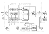
- FIG. 2 is a functional block diagram of the speech processing unit illustrated in FIG. 1 which applies signal processing operations to a sound signal in accordance with one embodiment of the present invention
- FIG. 3 is a functional block diagram of the modifier rules illustrated in FIG. 2 , in accordance with one embodiment of the present invention.
- FIG. 4 is an example of an input/output function implemented in one embodiment of the present invention to modify the modulation depth of the envelope curve
- FIG. 5A depicts an exemplary envelope signal for a voiced passage of speech in a single channel and the subsequent modified envelope signal as processed by one embodiment of the modulation depth enhancer illustrated in FIG. 3 ;
- FIG. 5B depicts an exemplary envelope signal for a voiced passage of speech in a single channel and the subsequent modified envelope signal as processed by one embodiment of the modulation depth enhancer illustrated in FIG. 3 ;
- FIG. 6A is an electrodogram of sound signals to show the effect of implementing an embodiment of the present invention.
- FIG. 6B is an electrodogram of sound signals to show the effect of implementing an alternative embodiment of the present invention.
- FIG. 7 is a schematic block diagram of an embodiment of the signal processing applied by an embodiment of the MDE algorithm
- FIG. 8 is a schematic block diagram of an embodiment of the signal processing applied by an embodiment of the MDE algorithm
- FIG. 9 is a schematic block diagram of one embodiment of the speech processing unit illustrated in FIG. 1 ;
- FIG. 10 is a schematic representation of the phase alignment algorithm
- FIG. 11 is a schematic representation of the time shift processing system
- FIG. 12A is a display of a stimulus output pattern, or electrodogram, of amplitude modulated sound signals reflecting the effect of the implementation of one embodiment of the present invention
- FIG. 12B is a display of a stimulus output pattern, or electrodogram, of amplitude modulated sound signals reflecting the effect of the implementation of one embodiment of the present invention
- FIG. 13 is a schematic representation of the signal processing applied to the sound signal in accordance with the present invention.
- FIG. 14 depicts a signal waveform at various locations in the schematic representation of the signal processing path of one embodiment of the invention.
- FIG. 15 depicts a signal waveform at various locations in the schematic representation of the signal processing path of one embodiment of the invention.
- FIG. 16 depicts a signal waveform at various locations in the schematic representation of the signal processing path of one embodiment of the invention.
- FIG. 17 depicts a signal waveform at various locations in the schematic representation of the signal processing path of one embodiment of the invention.
- FIG. 18 depicts a signal waveform at various locations in the schematic representation of the signal processing path of one embodiment of the invention.
- FIG. 19 depicts a signal waveform at various locations in the schematic representation of the signal processing path of one embodiment of the invention.
- FIG. 20 depicts a signal waveform at various locations in the schematic representation of the signal processing path of one embodiment of the invention.
- FIG. 21 depicts a signal waveform at various locations in the schematic representation of the signal processing path of one embodiment of the invention.
- FIG. 22 depicts a signal waveform at various locations in the schematic representation of the signal processing path of one embodiment of the invention.
- FIG. 23 is an electrodogram (stimulus output pattern) of sound signals to show the overall effect of the implementation of one embodiment of the present invention.
- FIG. 24 is an electrodogram (stimulus output pattern) of sound signals to show the overall effect of the implementation of one embodiment of the present invention.
- FIG. 25 is an electrodogram (stimulus output pattern) of sound signals to show the overall effect of the implementation of one embodiment of the present invention.
- FIG. 26 depicts a signal waveform at various locations in the signal processing path for an alternative embodiment of the present invention.
- FIG. 27 depicts a signal waveform at various locations in the signal processing path for an alternative embodiment of the present invention.
- FIG. 28 depicts a schematic representation of an alternative embodiment of the invention.
- FIG. 29 depicts a signal waveform at various locations in the signal processing path for an alternative embodiment of the present invention.
- FIG. 30 depicts a signal waveform at various locations in the signal processing path for an alternative embodiment of the present invention.
- FIG. 31 depicts a signal waveform at various locations in the signal processing path for an alternative embodiment of the present invention.
- FIG. 32 depicts a signal waveform at various locations in the signal processing path for an alternative embodiment of the present invention.
- FIG. 33 depicts a signal waveform at various locations in the signal processing path for an alternative embodiment of the present invention.
- FIG. 34 depicts a signal waveform at various locations in the signal processing path for an alternative embodiment of the present invention.
- FIG. 35 depicts the input/output function for modulation depth plotted on log dB scales for embodiments of the MEM strategy aspect of the present invention.
- MDE Modulation Depth Enhancement
- modulation depth when the ratio of the peak level to the trough level of the envelope signal in that channel (“modulation depth” herein) over some finite time period is less than a threshold value, the modulation depth is increased by, for example, some constant function, in a smoothly varying fashion, or by different functions at defined breakpoints. This expansion may provide improved identification of the modulation frequency and thus the voicing or musical pitch of the sound signal.
- the amplitude-modulated narrow-band envelope signals may differ in phase between channels.
- Experimental findings with cochlear implant recipients have shown that phase differences between modulation signals in neighboring channels (for example, spacing of 3 to 5 electrode channels, or spacing of approximately 2 to 4 mm) can compromise identification of modulation frequency due to temporal integration of signals across channels (McKay & McDermott, 1996; and work in progress by the present applicant), and/or spread of the electrical stimulus current field.
- One aspect of the present invention implements what is generally and collectively referred to herein as Phase Alignment techniques to minimize the phase differences between peaks in amplitude-modulated envelope signals across channels. Such phase alignment may improve modulation frequency perception.
- Another aspect of the present invention is generally directed to modulating the narrow band envelope signals in each channel by a broadband envelope signal derived from the input sound signal, such that the phase of modulated signals in the narrow band channels are synchronized.
- the broadband envelope signal contains modulation components related to the fundamental frequency of the input sound signal. In the specific case of speech, this includes the voicing frequency. Consequently, modulation information related to the fundamental frequency is provided on all narrow band channels. Additionally, in certain embodiments, the modulation depth (for voicing frequency components, for example) in the broadband envelope signal is increased, and accordingly the average modulation depth in each channel is generally increased, so that the modulation frequency information may be more reliably perceived by the recipient.
- Embodiments of the present invention are described herein primarily in connection with one type of stimulating medical device, an auditory prosthesis.
- Auditory prostheses include but are not limited to hearing aids, auditory brain stimulators, and CochlearTM implants (also commonly referred to as CochlearTM prostheses, CochlearTM devices, CochlearTM implant devices, and the like; generally and collectively referred to as “cochlear implants” herein).
- Cochlear implants use direct electrical stimulation of auditory nerve cells to bypass absent or defective hair cells that normally transduce acoustic vibrations into neural activity.
- FIG. 1 is a perspective view of an exemplary cochlear implant in which embodiments of the present invention may be implemented, for example, to improve the voice pitch perception of a recipient of the device.
- outer ear 101 comprises an auricle 110 and an ear canal 102 .
- An acoustic pressure or sound wave 103 is collected by auricle 110 and channeled into and through ear canal 102 .
- a tympanic membrane 104 Disposed across the distal end of ear cannel 102 is a tympanic membrane 104 which vibrates in response to acoustic wave 103 .
- This vibration is coupled to oval window or fenestra ovalis 112 through three bones of middle ear 105 , collectively referred to as the ossicles 106 and comprising the malleus 108 , the incus 109 and the stapes 111 .
- Bones 108 , 109 and 111 of middle ear 105 serve to filter and amplify acoustic wave 103 , causing oval window 112 to articulate, or vibrate.
- Such vibration sets up waves of fluid motion within cochlea 116 .
- Such fluid motion activates tiny hair cells (not shown) that line the inside of cochlea 116 .
- Activation of the hair cells causes appropriate nerve impulses to be transferred through the spiral ganglion cells (not shown) and auditory nerve 114 to the brain (not shown), where they are perceived as sound.
- Cochlear implant system 100 comprises external component assembly 143 which is directly or indirectly attached to the body of the recipient, and an internal component assembly 144 which is temporarily or permanently implanted in the recipient.
- External assembly 143 typically comprises microphone 124 for detecting sound, a speech processing unit 126 , a power source (not shown), and an external transmitter unit 128 .
- External transmitter unit 128 comprises an external coil 130 and, preferably, a magnet (not shown) secured directly or indirectly to the external coil.
- Speech processing unit 126 processes the output of microphone 124 that is positioned, in the depicted embodiment, by ear 110 of the recipient.
- Speech processing unit 126 generates coded signals, referred to herein as a stimulation data signals, which are provided to external transmitter unit 128 via a cable (not shown).
- Speech processing unit 126 is, in this illustration, constructed and arranged so that it can fit behind outer ear 110 . Alternative versions may be worn elsewhere on the recipient's body.
- Internal component assembly 144 comprise an internal receiver unit 132 , a stimulator unit 120 and an electrode assembly 118 .
- Internal receiver unit 132 comprises an internal transcutaneous transfer coil (not shown), and preferably, a magnet (also not shown) fixed relative to the internal coil.
- Internal receiver unit 132 and stimulator unit 120 are hermetically sealed within a biocompatible housing. The internal coil receives power and data from external coil 130 , as noted above.
- a cable or lead of electrode assembly 118 extends from stimulator unit 120 to cochlea 116 and terminates in an array 142 of electrodes. Signals generated by stimulator unit 120 are applied by the electrodes of electrode array 142 to cochlear 116 , thereby stimulating the auditory nerve 114 .
- external coil 130 transmits electrical signals to the internal coil via a radio frequency (RF) link.
- the internal coil is typically a wire antenna coil comprised of at least one and preferably multiple turns of electrically insulated single-strand or multi-strand platinum or gold wire.
- the electrical insulation of the internal coil is provided by a flexible silicone molding (not shown).
- internal receiver unit 132 may be positioned in a recess of the temporal bone adjacent ear 110 of the recipient.
- implant system 100 may be a totally implantable prosthesis.
- speech processor 116 including the microphone, speech processor and/or power supply may be implemented as one or more implantable components.
- speech processor 116 may be contained within the hermetically sealed housing used for stimulator unit 126 .
- tissue-stimulating medical devices examples include, but are not limited to, other sensory prosthetic devices, neural prosthetic devices, and functional electrical stimulation (FES) systems.
- FES functional electrical stimulation
- information is collected by electronic sensors and delivered directly to the nervous system by electrical stimulation of pathways in or leading to the parts of the brain that normally process a given sensory modality.
- Neural prostheses are clinical applications of neural control interfaces whereby information is exchanged between neural and electronic circuits.
- FES devices are used to directly stimulate tissue having contractile cells to produce a controlled contraction of the same.
- the present invention relates to an improvement which is applicable to a wide range of sound processing strategies for auditory prostheses, as well as other applications. Accordingly, the following implementation is not to be taken as limitative of the scope or applicability of the present invention.
- SMSP SMSP
- McDermott, & Vandali 1991; McDermott, McKay, & Vandali, 1992
- SPEAK Skinner et. al., 1994; Whitford et. al., 1995
- ACE Advanced Combinational Encoder
- embodiments of the present invention may equally be applied to other speech coding strategies such as the Continuous Interleaved Sampling (CIS) strategy (Wilson et. al., 1991).
- CIS Continuous Interleaved Sampling
- a received sound 103 is processed to produce a set of signals in spaced frequency channels. Then, for at least some frequency channel signals, when the ratio of the peak level to the trough level of the envelope signal in that channel (“modulation depth” herein) over some finite time period is less than a threshold value, the modulation depth is increased.
- the modulation depth may be expanded by, for example, some constant function when it is below a given threshold, in a smoothly varying fashion, or by different functions at defined breakpoints. Alternative parameters could be adjusted, which have the effect of expanding the modulation depth. This expansion may provide improved identification of the modulation frequency and thus the voicing or musical pitch of the sound signal.
- embodiments of this aspect of the present invention are applicable to processing sound signals for auditory prostheses, including cochlear implants such as the one described above with reference to FIG. 1 , and hearing aids, as well as other applications where it may be desirable to improve the perception of voice pitch or musical tone.
- FIG. 2 is a functional block diagram of one embodiment of the relevant portions of speech processing unit 126 illustrated in FIG. 1 .
- speech processing unit 126 comprises a pre-amplifier 202 which amplifies the received sound signals and provides them to a filter bank 204 .
- Filter bank 204 is a bank of N parallel filter channels 206 tuned to adjacent frequencies.
- the quantity of parallel filter channels 206 (that is, N) is 16 consistent with the conventional SMSP strategy. It should be understood, however, that in alternative implementations any quantity of filter channels 206 may utilized.
- filter bank 204 comprises 20 filter channels 206 .
- Each filter channel 206 comprises a band-pass filter (BPF) 208 and an envelope detector 210 .
- Band-pass filters 208 are typically narrow (approximately 180 Hz) for apical (low-frequency) channels and increase in bandwidth (typically up to 1000 Hz or more) for more basal (higher frequency) channels.
- Envelope detector 210 provides an estimate of the narrow-band envelope signal in each frequency channel.
- envelope detectors 210 effectively comprise a full-wave (quadrature) rectifier followed by a low-pass filter.
- Envelope detectors 210 typically pass fundamental (modulation) frequency information up to approximately 180 Hz to 400 Hz although for some implementations higher frequencies may be passed.
- filter bank 204 is implemented using either a Fast Fourier Transform (FFT) or a Finite Impulse Response (FIR) filter bank (which uses complex coefficients). Both implementations effectively perform the band-pass filtering, full-wave (quadrature) rectification and low-pass filtering operations.
- FFT Fast Fourier Transform
- FIR Finite Impulse Response
- One implementation of the FFT filter bank embodiment provides a fixed low-pass filter cut-off frequency (for ⁇ 3 dB gain) of 180 Hz.
- the complex coefficient FIR filter bank embodiment provides a low-pass filter cut-off frequency equal to the ( ⁇ 3 dB) bandwidth of the band-pass filters.
- Basal (high frequency) channels can be as wide as 1000 Hz or more and thus an additional second-order low-pass filter (with a cut-off frequency of 400 Hz) can optionally be employed to remove from the envelope signals any frequencies above the fundamental voicing frequency.
- the advantage of employing the complex coefficient FIR over the FFT filter banks is that higher voicing frequencies can be passed, provided that the band-pass filters are wider than 180 Hz.
- Filter bank 204 may be implemented to provide an estimate of the envelope signals in each frequency channel at regular time intervals known as the analysis or update rate.
- the SMSP strategy conventionally employs a relatively low analysis rate of approximately 250 Hz. However, in this implementation a much higher update rate of approximately 1200 to 1600 Hz is employed so that modulation frequencies of approximately 300 to 400 Hz can be adequately sampled.
- update rates are available with current commercial cochlear implants and speech coding strategies such as ACE. It is known from amplitude modulation identification experiments with cochlear implant recipients that update/stimulation rates of at least four times the modulation frequency are preferred for adequate analysis/coding of the signal (McKay, McDermott, & Clark, 1994).
- the frequency channel envelope signals 212 generated by N-channel filter bank 204 are modified by a modulation depth enhancer (MDE) 214 , as described herein, prior to further processing by speech processing unit 126 in accordance with the implemented speech coding strategy.
- Modulation depth enhancer 214 independently operates on the narrow-band envelope signals in each filter bank channel.
- Modulation depth enhancer 214 comprises an envelope signal modifier 216 that modifies the envelope signals of selected frequency channels to increase the modulation depth of the envelope signal. Modulation depth enhancer 214 makes such modifications based on modification parameters 220 generated by modulation depth analyzer 218 .
- FIG. 3 is a functional block diagram of one embodiment of the modulation depth analyzer 218 illustrated in FIG. 2 .
- modulation depth anaylzer 218 receive frequency channel signals 212 from filter bank 204 .
- a peak and trough estimator 302 of modulation depth analyser 218 utilizes conventional techniques now or later developed to identify the maximum amplitude or peak (P n ) and the minimum amplitude or trough (T n ) of the envelope signal for each frequency channel.
- the peak and trough levels of the envelope signal in each channel are estimated over a finite time period using a sliding time window of duration ( ⁇ ).
- a modulation depth estimator 304 of modulation depth analyser 218 estimates the modulation depth of the envelope signals in each channel 212 based on the peak and trough values generated by estimator 302 .
- modulation depth estimator 304 applies the algorithm shown in Equation (1) to generate a corresponding estimated modulation depth 312 .
- MD n P n /T n (1)
- the duration of the sliding time window ( ⁇ ) is typically 10 to 15 ms and is of sufficient duration to analyze fundamental voicing frequencies as low as 100 Hz.
- modulation depth estimator 304 Because the modulation depth is estimated over some finite duration, rather than instantaneously, the estimate must be referenced from a time point corresponding to the middle of the time window. Thus a processing delay of ⁇ /2 is introduced for all processing following the modulation depth estimation performed by modulation depth estimator 304 .
- the estimated modulation depth 312 for each channel is modified by modulation depth modifier 306 according to input/output functions to effectively increase the modulation depth.
- a power function is used to expand the modulation depth for cases when it is less than some knee point (typically 6 dB).
- the order of the power function is typically 2 or 3.
- a linear function is used to modify the modulation depth. For modulation depths above this limit point the modulation depth is unchanged.
- modulation depth modifier 306 modifies the modulation depth in accordance with the following process:
- Equation (3) For modulation depths greater than the Knee point but less than some Limit point (L MD ), which typically equals 10 (20 dB), the modulation depth is increased in accordance with a linear function, as shown in Equation (3).
- MD′ n MD n ⁇ A+B for K MD ⁇ MD n ⁇ L MD and K MD X MD ⁇ L MD (3)
- FIG. 4 is a curve illustrating one example of an input/output function implemented in modulation depth modifier 306 .
- the curve 400 is plotted on a log-log dB scale, for the modulation depth using a Knee point of 2 (6 dB), a Limit point of 10 (20 dB), and an Expansion factor of 3.
- the envelope signals (e n ) 212 are modified (e′ n ) 222 so as to achieve the desired modifications to the modulation depth.
- the modulation depth is equal to the peak-to-trough ratio of e n calculated over some finite interval ( ⁇ ).
- ⁇ the peak-to-trough ratio of e n calculated over some finite interval
- both the peak and trough levels could be adjusted so as to preserve the average level. This approach would be recommended for non-cochlear implant prosthesis (such as hearing aids).
- peaks of electrical stimulation contribute mostly to the perceived loudness of the signal and thus to minimize loudness changes, the peaks should be preserved and only the troughs of the envelope signals modified.
- a linear equation is implemented in envelope signal modifier 216 to modify the continuum of levels in envelope signals 212 .
- Use of a linear function will preserve the shape of envelope signal 212 within each voicing period (or periodic cycle).
- Equation (6) One example of such a linear equation which may be employed to modify the continuum of levels in the envelope signal is shown in Equation (6).
- FIG. 5A displays an exemplary unmodified envelope signal e n 212 and modified envelope signal e′ n 222 in one channel for a typical voiced passage of speech.
- the parameters used represent only one possible strategy possible under the implementation described.
- the inventors have tested alternative parameters for the strategy.
- a knee point of 10 dB, a limit point of 80 dB, and an expansion power of 7 (below the knee point) were implemented. This provides a greater expansion of modulation depth.
- An alternative embodiment provides more moderate expansion, with a knee point of 6 dB, a limit of 40 dB, and an expansion power of 4.
- Alternate functions rather than a linear equation for modification of the continuum of levels in the envelope signal could be employed. For instance, it may be desirable to better preserve the peak level by using a second- or higher-order equation that adjusts levels in the trough region (that is, levels below the average or mid-point of the envelope signal) more than those in the peak region (that is, levels above the mid-point of the envelope signal). This would ensure less change to the loudness of the peaks and thus less change to the overall loudness of the perceived signal after processing. It will however distort the shape of the envelope signal within each voicing period.
- FIG. 5B displays an example unmodified (e n ) and modified (e′ n ) envelope signal that may be generated when this embodiment is implemented.
- peak and trough estimator 302 will also calculate the mid-point level (M n ), and parameter generator 310 calculates C n and D n relative to the mid-point rather than the peak level.
- the modified envelope signals e′ n 222 replace the original envelope signals e n 212 derived from the filter bank 204 and processing then continues as per the original speech coding strategy.
- the M selected channels are then used by encoder 224 to generate M electrical stimuli corresponding in stimulus intensity and electrode number to the amplitude and frequency of the M selected channels.
- M stimuli are transmitted to internal components 144 of cochlear implant 100 via a radio-frequency link and are used to activate M corresponding electrode sites.
- the modulation depth enhancement may be applied to the channelized sound signal, and subsequent processing continues as per any selected processing strategy for cochlear implant 100 .
- This strategy is specific to this stage of processing, and hence is applicable to any strategy which employs channelization and subsequent processing (with modifications as may be dictated by the requirements of the selected strategy).
- modulation depth enhancer 700 comprises a modulation depth analyser 704 and an envelope signal modifier 702 .
- Modulation depth analyzer 704 comprises a signal depth estimator 708 that generates a signal depth (sd n ) 710 that represents the ratio of the peak level (generated by peak detector 706 ) to the envelope signal level at any time point and be defined as shown in Equation (9).
- FIG. 8 is a functional block diagram of another embodiment of modulation depth enhancer 214 , referred to herein as modulation depth enhancer 800 .
- Modulation depth enhancer 800 comprises an envelope signal modifier 802 and a modulation depth analyser 804 .
- Modulation depth analyser 804 comprises a peak, trough and mid-point estimator 806 and signal depth estimator 808 operationally coupled as shown.
- the loudness of the processed signal might be better preserved by restricting envelope signal modifier 802 to perform signal modification to those time points in which envelope signal 212 is less than the mid-point (that is, M n as defined in Equation (7)) between its peak and trough levels. It is noted that computational time may be reduced as calculation of the “signal depth” is expensive as it requires a divide operation.
- Modification of the envelope signal could simply be restricted to points in which the envelope signal is less than the mid-point (that is, e n ⁇ M n ). As noted above, this will introduce distortion of the envelope signal (that is, a step change in the envelope signal level) at values around the mid-point. However, for cochlear implants this may not be problematic as it is unlikely that this sort of distortion is noticeable or destructive to the signal. For non-cochlear implant prostheses such as hearing aids this sort of distortion may be noticeable and should be avoided.
- Equation (9) the equation for the “signal depth”, as shown in Equation (9), as a function of the mid-point, rather than the peak, of the envelope signal level.
- sd n M n /e n for e n ⁇ M n (13)
- Equations (10), (11) and (12) can be used by envelope signal modifier 802 to derive equations for the modified envelope signal (e′ n ) 214 as a function of the “signal depth” 810 generated by signal depth estimator 808 as defined in Equation (14) for all time point in e n which are less than the mid-point M n as determined at block 806 .
- This embodiment is reflected in Equations (15), (16) and (17), respectively.
- Equations (10) . . . (12) because the “signal depth” is now relative to the mid-point, rather than the peak.
- the modulation depth or “signal depth”
- the modulation depth expansion factor will be less than X MD (that is, approximately X MD ⁇ 0.5).
- stimulus output patterns known as electrodograms (which are similar to spectrograms for acoustic signals), which plot stimulus intensity (plotted as log current level) for each electrode (channel) as a function of time, were recorded for the SMSP and MDE strategies and are shown in FIGS. 6A and 6B , respectively.
- the speech token presented in these recordings was “lime” and was spoken by a female speaker having a fundamental voicing frequency of approximately 200 Hz.
- the electrodogram for the MDE strategy depicts the response for the algorithm as described above with reference to Equations (13) through (17).
- the MDE Knee point was set to 6 dB, the Limit point to 20 dB and the Expansion factor to 3.
- the effect of the MDE strategy can be seen by comparing FIGS. 6A and 6B .
- the above MDE algorithm is configured or adapted to a form suitable for implementation in a real-time digital signal processor (DSP).
- DSP real-time digital signal processor
- At least two criteria may be considered in such embodiments.
- First, fixed-point DSP processing utilizes numerical values less than or equal to 1.0.
- the modulation depth that is, the ratio of the peak-to-trough level which is a value that is always greater than or equal 1.0
- the parameters must either be scaled such that they fall into a usable range below 1.0, or inverted (that is, reciprocal) such that they will never be greater than 1.0.
- the modulation depth and “signal depth” inverted values are utilized.
- Second, DSPs are typically efficient at performing add, subtract and multiply operations, but not divisions. Thus the processing is preferably arranged so as to minimize the number of required division operations.
- Knee point and Limit point are subsequently inverted and Equations (2), (3) and (4) can be re-written as set out next below.
- Equation (7) ( P n +T n )/2 (7-DSP)
- Knee point and Limit point are subsequently inverted and Equations (10) through (12) may be re-written as set out next below.
- Equations (14) through (17) can be employed with the restriction that the “signal depth” and thus the modified envelope signal level is only calculated when the envelope signal level is less than the mid-point level.
- Knee point and Limit point are subsequently inverted and Equations (15) through (17) can be re-written as set out next below.
- the amplitude-modulated narrow-band envelope signals 212 may differ in phase between frequency channels.
- the inventors have observed that phase differences between modulation signals in neighboring channels compromises recipients' ability to identify the modulation frequency, and that temporal pitch perception is improved when the temporal peaks across channels are aligned.
- the effect of phase alignment among the envelope signals of neighboring or adjacent frequency channels may be due to, for example, the temporal integration of signals across channels and/or the spread of the electrical stimulus current field.
- Embodiments of this next aspect of the present invention implement what is generally and collectively referred to herein as the phase alignment techniques to minimize the phase differences between peaks (that is, time difference between temporal peaks) in amplitude-modulated envelope signals across channels.
- the envelope for each channel is determined and the temporal peaks are identified.
- a timing offset is then applied to selected channel signals to reduce the phase differences between the temporal peaks.
- These phase-adjusted signals are then used as the basis for further processing.
- Some embodiments reduce the phase differences between channel signals across all channels using a common reference signal, reduce the phase differences between some channels and not others (for example aligning only channels within a certain frequency range), and align channels within different frequency bands to different reference signals.
- the present invention provides a sound processing process comprising: determining an envelope for each channel signal, the envelope being determined so as to retain information about the fundamental frequency; determining temporal peaks in the envelope of at least selected channel signals, the peaks being related to the fundamental frequency; and selectively applying a timing offset to adjust the timing of the peaks in the selected channel signals, the adjustment being made in response to a predetermined instruction set, so that the phase differences between the peak values in at least the selected channel signals are reduced.
- the present invention provides a sound processing process, comprising: determining for each channel signal a channel envelope that retains information about the fundamental frequency of the sound signal; determining a reference signal corresponding to the sum of channel envelopes in a plurality of channels; determining the timing of temporal peaks in each of the channel envelopes and in the reference signal, the peaks being related to the fundamental frequency of the sound signal; determining a timing offset for at least some of the channels, using a predetermined instruction set, by reference to at least the difference in timing between the peaks in the reference signal and the corresponding peaks in each channel envelope; adjusting the timing of the channel signal in the selected channel signals in accordance with the timing offsets, so that the phase differences between the peak values in at least the selected channel signals are reduced; and determining subsequent reference signals from a sum of the time-shifted signals in the channels.
- a reference envelope signal is established to which the phase of the envelope signals in each channel can be aligned.
- the modulation frequency of the reference signal corresponds to the fundamental voicing frequency of the input sound signal and is sufficiently robust to be resistant to the effects of competing noise.
- a phase offset (or time shift) for each channel is determined so as to best align the peaks in the temporal envelope of each channel with that of the reference signal.
- the time shift can be, for example, up to half the lowest expected voicing/modulation period (for 80 Hz this is approximately 6 ms) and can be a positive or negative time shift (i.e. ⁇ 6 ms).
- a temporal peak detection algorithm is preferably used to determine the location in time of maximum turning points (peaks) in the envelope signal. Small peaks or peaks too close in time are ignored. Having established the peak times for a channel, the peak times are aligned (if possible) with those of the reference signal by introducing a time shift to the channel in question.
- an optimum time shift is determined based on an analysis of the combination (product or summation or similar rule) of the reference signal and the frequency channel in question for all possible time shifts. Finally, the phase offset (time shift) is applied to each channel so as to minimize distortion of the envelope signals resulting from the time shift.
- the reference signal in a preferred form is generated using an iterative procedure. Initially, all filter bank envelope signals are summed together over some finite time window. Given a positive signal-to-noise ratio at least some of the channels contain periodicity information pertaining to the fundamental voicing/modulation frequency. This reference signal is used to adjust the phase offset (time shift), using the techniques described herein, of each channel in turn for the given time window. Processing would then begin again for the next time window/pass except in this case the reference signal would be constructed by summing the time shifted channel signals together. Distortion in each channel due to dynamic adjustment of the time shift may be minimized by low-pass filtering the time shift and/or only applying it at time points for a given channel where its envelope signal is at a local minimum (temporal trough).
- the phase offset (time shift) for each channel will converge within a few iterations (time steps) on some value that aligns the temporal peaks of each channel. Furthermore, provided that the fundamental voicing or modulation frequency does not change too rapidly the phase alignment approach of the present invention will adapt and follow the changes in frequency over time. For unvoiced (non-periodic) signals the phase offset for each channel would vary randomly. However given that the location in time of temporal peaks for unvoiced signals varies randomly, this is unlikely to impose any adverse effects. For voiced (periodic) signals combined with noise, the present invention will align any periodic temporal patterns available in the envelope signals of each channel, with alignment errors being inversely proportional to some function of the signal-to-noise ratio.
- the present invention may be implemented using alternative methods for generating or applying the reference signal, provided that the broad functional intention of supplying additional information about the fundamental frequency (F0) and reducing phase differences between channels is met.
- ACE Advanced Combinational Encoder
- CIS Continuous Interleaved Sampling
- the present invention is principally described with reference to a cochlear implant system, the invention is not limited to such an implementation.
- FIG. 9 is a schematic block diagram of one embodiment of the speech processing unit illustrated in FIG. 1 , referred to herein a speech processing unit 900 .
- Each filter channel 206 includes a band-pass filter 208 and an envelope detector 210 to provide an estimate of the narrow-band envelope signal 212 in each channel.
- Band-pass filters 208 may be narrow (approximately 180 Hz wide ⁇ 3 dB bandwidth) for apical (low-frequency) channels and increase in bandwidth (typically up to 1000 Hz or more) for more basal (higher frequency) channels.
- Envelope detectors 210 which effectively comprise a full-wave (quadrature) rectifier followed by a low-pass filter, typically pass fundamental (modulation) frequency information up to approximately 200 Hz but for some implementations (including this preferred embodiment) can accommodate frequencies as high as approximately 400 Hz.
- Filter bank 204 is used to provide an estimate of the envelope signals 212 in each channel at regular time intervals known as the analysis or update rate.
- the ACE strategy can employ an update rate which can be adjusted from as low as approximately 200 Hz up to as high as approximately 4000 Hz (depending on the hardware device used).
- an update rate of approximately 1200 Hz (or 1600 Hz) is employed so that modulation frequencies of approximately 300 Hz (or 400 Hz) can be adequately sampled (note, amplitude modulation identification experiments with recipients of cochlear implant prostheses have indicated that update/stimulation rates of at least four times the modulation frequency are required for adequate analysis/coding of the signal, McKay, McDermott, & Clark, 1994).
- the envelope is determined so as to retain information about the fundamental frequencies for the intended application.
- the range covering the voicing frequency (F0) should be captured. Otherwise, the desired pitch information will not be supplied to the recipient.
- the outputs 212 of N-channel filter bank 204 are then processed by the phase alignment module 902 which minimizes the phase difference (or align temporal peaks) between amplitude-modulated envelope signals 212 across channels n, prior to further processing by the speech coding strategy. In one embodiment, this is carried out for all channels in the system, while in an alternative embodiment, this is carried out for at least those channels in the voiced frequency range (i.e. first, second and third formant frequency range which ranges from approximately 100 Hz up to 3 to 4 KHz). Other channel selection criteria may be implemented in alternative embodiments.
- Phase alignment module 902 comprises an array of channel envelope buffers 904 , a reference signal generator 916 and a time shift processor 906 . Phase alignment module 902 is illustrated in greater detail in FIGS. 10 and 11 .
- the channel envelope signals 212 derived from filter bank 204 are stored in channel envelope buffers 904 which are used by reference signal generator 916 to construct a reference signal 908 and are further used by time shift processor 906 to calculate appropriate time shifts 912 for each channel so as to align temporal peaks in the reference signal to those of channel signals.
- the calculated time shifts 912 are applied to envelope signals 212 of each channel. These time shifted envelope signals 914 effectively replace the original envelope signals 212 derived from filter bank 204 and processing then continues as per the original speech coding strategy.
- the M selected channels are then used by encoder 224 to generate M electrical stimuli 8 corresponding in stimulus intensity and electrode number to the amplitude and frequency of the M selected channels. These M stimuli are transmitted to internal components 144 of cochlear implant 100 via a radio-frequency link and are used to activate M corresponding electrode sites.
- This algorithm may be applied to the channelized sound signal, and subsequent processing continues as per any chosen processing strategy for the cochlear implant.
- This strategy is specific to this stage of processing, and hence is applicable to any strategy, which employs channelization and subsequent processing (with modifications as may be dictated by the requirements of the selected strategy).
- the first task of phase alignment module 902 is to construct a reference signal 908 for which envelope channel signals can be aligned to.
- the time shifts (phase offsets) for all channels are initialized to zero and reference signal 908 is generated by summing 910 channel envelope signals 212 for each time point into the reference signal buffer.
- the time shifts will vary and thus will result in construction of the reference signal from time shifted channel envelope signals.
- the time shift can be up to half the lowest expected voicing/modulation period (for 80 Hz this is approximately 6 ms) and can be a positive or negative time shift (i.e. ⁇ 6 ms).
- the channel envelope signal buffers 904 which hold the channel envelope signals 212 used to construct the reference signal 908 must be at least the length of the reference signal buffer (25 ms) plus twice the maximum time shift (2 ⁇ 6 ms) which equals 37 ms.
- any channels that contain modulated signals that are aligned in phase with respect to one another will sum constructively so as to enforce the modulated signal in reference signal 908 .
- channels that contain modulated signals 212 that are out of phase with one another will tend to diminish or introduce additional peaks in reference signal 908 .
- Modulated signals that are 180 degrees out of phase will be the most destructive.
- reference signal 908 (that is, combination of all channels) will contain modulation terms that are related to the fundamental frequency of the received sound signal 103 but that the strength of these terms will vary with characteristics of the input signal and the band-pass filter bank 204 used to analyse the input signal. It is also anticipated that higher frequency modulation terms may be present in reference signal 908 . The relative amplitude of the fundamental frequency signal to the higher frequency modulation terms will also vary with characteristics of input signal 103 and band-pass filter-bank 204 . However, in subsequent time frames, if the time shifts for each channel are adjusted so as to align temporal peaks then this will result in strengthening of the fundamental frequency terms in reference signal 908 .
- time shift processor 906 depicts the processing path for this operation for one channel envelope signal 212 .
- FIG. 11 is a schematic block diagram of one embodiment of time shift processor 906 .
- the channel envelope signal 212 is shifted in time and stored in buffer 1106 so as to align the peak with a peak in reference signal 908 .
- a correlation, of sorts, between reference signal 908 and the shifted channel envelope signal is then performed by multiplier 1108 , adder 1110 and time shift determinator 1114 .
- the correlation is carried out by multiplying at multiplier 1108 each time point in the time-shifted channel envelope signal 1106 by each time point in the reference signal 908 and summing at adder 1112 the multiplied terms 1110 . These operations are carried out consecutively for all peaks in the channel envelope signal 212 and reference signal 908 .
- An optimal time shift is then determined at block 1114 by selecting the smallest time shift (from peak detector 1104 ), compared to the current time shift, which provides the largest correlation term (derived from adder 1112 ). These operations are carried out for all channels and the optimal time shifts are then used to shift the channel envelope signal buffers 904 in time.
- the time shifted channel envelope signals from block channel envelope buffers 904 are referenced from a time point mid-way through the channel envelope buffers plus or minus the time shift.
- stimulus output patterns known as electrodograms (which are similar to spectrograms for acoustic signals), which plot stimulus intensity (plotted as log current level) for each electrode (channel) as a function of time, were recorded for the ACE strategy shown in FIG. 12( a ) and for application of the phase alignment to the ACE strategy shown in FIG. 12( b ).
- the sound signal used in these recordings include two sinusoidal amplitude modulated (SAM) pure tones of frequencies 600 and 1200 Hz respectively.
- the modulation frequencies for both SAM tones was 100 Hz and the modulation phase difference between SAM tones was 180 degrees.
- additional processing and/or optimizations may be carried out to improve the performance of phase alignment module 902 .
- additional processing and/or optimizations may include one or more of the following.
- distortion in channel envelope signals 212 may be reduced by only applying an adjusted time shift value when the channel envelope signal level is at a trough (valley) or by low-pass filtering the time shift values.
- interactions between harmonic frequencies and the frequency boundaries imposed by filter bank 204 result in envelope channel signals 212 that contain periodic signals that follow the fundamental frequency but contain additional temporal peaks. These additional peaks lie between those of the underlying F0 pattern and introduce higher frequency modulation terms (for example, 2 or 3 times F0). In addition, the presence of noise will also introduce temporal peaks in the envelope signals, which are unrelated to the F0 periodicity.
- One approach to reducing some of these effects is to smooth (low-pass filter) the reference signal using an integration window (finite impulse response filter) of length related to an estimate of the fundamental voicing frequency (F0).
- an integration window finite impulse response filter
- F0 fundamental voicing frequency
- a fixed low-pass filter could be employed with a cut-off frequency of approximately 100 Hz that will attenuate the effect of higher order harmonics when F0 is low (that is, around 80-150 Hz).
- some of the processing blocks are bypassed when the signal level is small (e.g. below some threshold in which the effect of the algorithm will go unnoticed).
- processing time is reduced by calculating reference signal 908 and tine shifts 912 at a lower frequency (for example, decimation of the time shift operations by a factor of 2 or 4).
- a reference signal may be generated based only upon a band of channels, and used only to modify the phase of those signals.
- An example of this may be to modify phase only for signals in a range corresponding to voiced signals, and not modify other channels. In this instance, appropriate buffer times will be required to compensate for processing delays in other channels.
- This aspect of the present invention is generally directed to modulating the narrow band envelope signals in each channel by a broadband envelope signal derived from the input sound signal, such that the phase of modulated signals in the narrow band channels are synchronized.
- the broadband envelope signal contains modulation components related to the fundamental frequency of the input sound signal. In the specific case of speech, this includes the voicing frequency. Consequently, modulation information related to the fundamental frequency is provided concurrently in time on all narrow band channels. Additionally, in certain embodiments, the modulation depth (for voicing frequency components, for example) in the broadband envelope signal is increased, and accordingly the average modulation depth in each narrow-band channel is generally increased, so that the modulation frequency information may be more reliably perceived by the recipient.
- this aspect of the invention includes a sound processing device adapted to channel input sound signal 103 into a plurality of spaced frequency channels, such as speech processing unit 126 introduced above.
- Filter bank 204 comprises band-pass filters 208 and envelope detectors 210 that estimate the narrow-band envelope signal (which include both the slow envelope components of less than 50 Hz and higher envelope signal frequencies up to approx 400 Hz) of the signal in each spaced frequency channel.
- a broadband envelope detector 1306 measures the envelope of the broadband signal (for example, over a frequency range of 0 to 8 KHz) or a few broadband regions of the signal (for example, 0 to 4 KHz and 4 to 8 KHz); that enhances periodic information (for example, expanding the modulation depth of periodic terms) in the broadband envelope signal(s); and channel modulation module 1304 that uses the broadband envelope signal(s) 1307 to modulate the channelized narrow-band envelope signals 212 in unison.
- MAM Multi-channel Envelope Modulation
- ACE Advanced Combinational Encoder
- SMSP Spectral Maxima Sound Processor
- SPEAK Spectral Peak
- the invention is also equally applicable to other coding strategies such as the Continuous Interleaved Sampling (CIS) strategy (Wilson, et al., 1991).
- Each filter channel 206 includes a band-pass filter 208 and an envelope detector 210 to provide an estimate of the narrow-band envelope signal 212 in each channel e n .
- Band-pass filters 208 are typically narrow (approximately 180 Hz wide ⁇ 3 dB bandwidth) for apical (low-frequency) channels and increase in bandwidth (typically up to 1000 Hz or more) for more basal (higher frequency) channels.
- Envelope detectors 210 which effectively comprise a full-wave (quadrature) rectifier followed by a low-pass filter, typically pass fundamental (modulation) frequency information up to approximately 200 Hz but for some implementations can accommodate frequencies as high as approximately 400 Hz.
- the filter bank is used to provide an estimate of the narrow-band envelope signals (e n ) in each channel at regular time intervals known as the analysis or update rate.
- the ACE strategy employs an update rate which can be adjusted from as low as approximately 200 Hz up to as high as approximately 4000 Hz (depending on the hardware device used).
- an update rate of approximately 1200 Hz (or 1600 Hz) is employed so that modulation frequencies of approximately 300 Hz (or 400 Hz) can be adequately sampled (note, amplitude modulation identification experiments with users of cochlear implant prostheses have indicated that update/stimulation rates of at least four times the modulation frequency are required for adequate analysis/coding of the signal (McKay, McDermott, & Clark, 1994).
- FIGS. 14 through 22 will be used to illustrate the signal waveform at various locations in processing path.
- the signal used in these figures is the utterance “dog” spoken by a female speaker with an F0 of approximately 190 Hz. Note, only a portion of this utterance is depicted in these figures.
- the envelope of broadband signal 1307 as shown in FIG. 14 is derived by broadband envelope detector 1306 .
- the output of preamplifier 202 is provided to a full-wave rectifier 1316 that full-wave rectifies the signal to generate the signal shown in FIG. 15 .
- This signal is provided to a low-pass filter 1318 which, in one embodiment, applies a 300 Hz, 6 th order Butterworth, infinite impulse response (IIR) to generate the LPF envelope shown in FIG. 16 .
- IIR infinite impulse response
- the broadband envelope signal is then provided to a high-pass filter 1320 .
- High-pass filter 1320 removes the direct current (d.c.) and effectively expands modulation components corresponding to fundamental frequencies in the voiced speech range of 80 to 300 Hz.
- high-pass filter 1320 is an 80 Hz, 2 nd order Butterworth, IIR high-pass filter.
- the resulting signal is shown in FIG. 17 .
- a scaled version of the low-pass filtered signal generated by LPF 1318 is added to the envelope signal generated by high-pass filter 1320 by adder 1322 .
- the resulting signal is illustrated in FIG. 18 . As will be described in greater detail below, this allows for control of the expansion factor (or increase) applied to the modulation depth.
- the broadband envelope signal is then provided to a half-wave rectifier 1324 that half-wave rectifies the signal to remove any negative excursions in the signal that may arise from the high-pass filtering process performed at block 1320 .
- the scaling factor (EnvK) used to scale the low-pass filtered signal at multiplier 1330 can range from 0 to 8 and is typically equal to 0.5. Adjustment of the scaling factor (EnvK) allows for control of the expansion factor applied to the modulation depth in the envelope signal, with lower values providing deeper modulation.
- a scaling factor of 0.5 increases the modulation depth by a power of 3 approximately (at least for small modulation depths). For larger modulation depths, infinite expansion (or 100% modulation depth) is provided.
- the expansion power for the modulation depth is given by the equation P ⁇ (EnvK+1)/EnvK which holds for modulation depths in the original envelope of less than approximately 2 ⁇ EnvK+1.
- the expansion power is P ⁇ 3 for input modulation depths ⁇ 2 (or 6 dB).
- P approaches infinity (or 100% modulation depth).
- the expanded broadband envelope signal generated by half-wave rectifier 1324 is provided to normalizer 1326 which scales or normalises the amplitude of the signal such that its peak (or maximum) level over a finite time interval, which is measured using a sliding time window of approximately 12 ms in duration, is set to unity. This is achieved by multiplying the signal level by the inverse of the peak level derived from the sliding time window.
- the broad-band envelope signal is normalized to occupy a range of values from 0.0 to 1.0 with peak excursions (within a 12 ms interval) always reaching unity.
- the resulting signal is illustrated in FIG. 19 .
- the normalized broadband envelope signal 1307 is then used by channel modulation module 1304 to modulate the narrow-band envelope signals 212 derived from the N-channel filter bank 204 of the ACE strategy.
- FIG. 20 depicts a narrow-band envelope signal 212 derived from the frequency range of approximately 100 to 300 Hz.
- the narrow-band envelope signals 212 are first low-pass filtered at block 1308 to generate the signal shown in FIG. 21 .
- low-pass filter 1308 is a 50 Hz, 2 nd order Butterworth, IIR LPF. This removes any amplitude modulation in envelope signals 212 corresponding to typical fundamental frequencies in voiced speech signals. It will be understood that at this stage, the narrow band envelope signals 212 contain little more than level information.
- These smoothed (low-pass filtered) envelope signals generated by low-pass filter 1308 are then modulated at multipliers 1310 by normalized broadband envelope signal 1307 illustrated in FIG. 22 . Due to differences in the propagation time (or delay) through the broadband envelope signal path and the band-pass filter bank path, the broadband envelope signal is delayed at block 1328 by approximately 6 ms prior to being used to modulate the narrow-band envelope signals.
- the N-channel modulated narrow-band envelope signals (e′ n ) 1314 are then processed as per the normal ACE strategy.
- the M selected channels are then used to generate M electrical stimuli by encoder 1334 corresponding in stimulus intensity and electrode number to the amplitude and frequency of the M selected channels.
- These M stimuli are transmitted to implanted components 144 via a radio-frequency link established between transmitter unit 128 and a receiver included in internal components 144 , and are used to activate M corresponding electrode sites.
- FIGS. 23 through 25 To illustrate the effect of the MEM strategy on the coding of speech signals, stimulus output patterns, known as electrodograms (which are similar to spectrograms for acoustic signals), which plot stimulus intensity (plotted as log current level) for each electrode (channel) as a function of time, were recorded for the ACE and MEM strategies and are shown in FIGS. 23 through 25 .
- the speech token presented in these recordings was “dog” and was spoken by a female speaker having a fundamental voicing frequency of approximately 190 Hz.
- FIG. 23 displays the electrodogram for the ACE strategy.
- FIGS. 24 and 25 display electrodograms for the MEM strategy employing a scaling factor (Env K) of 4 and 1, respectively.
- MEM strategy of this aspect of the invention may be applied to the channelized sound signal, and subsequent processing may continue as per any selected processing strategy for cochlear implants.
- This strategy is specific to this stage of processing, and hence is applicable to any strategy which employs channelization and subsequent processing (with modifications as may be dictated by the requirements of the selected strategy).
- low-pass filter 1308 could be replaced by an envelope tracker that follows peaks in the signal (i.e. instantaneous attack time), holds peak signal levels (or uses a slow release time) for a period of approximately 12 ms (to smooth frequency components above approximately 80 Hz) after which a rapid release time constant is then applied.
- envelope tracker that follows peaks in the signal (i.e. instantaneous attack time), holds peak signal levels (or uses a slow release time) for a period of approximately 12 ms (to smooth frequency components above approximately 80 Hz) after which a rapid release time constant is then applied.
- the output of this peak envelope tracker is shown in FIG. 26 and the modulated channel output in FIG. 27 .
- the low-pass filter 1318 used to estimate the broadband envelope signal can be reduced in its cut-off frequency so that the unwanted affect of higher order harmonics in the envelope when F0 is low (e.g. below 150 Hz) can be minimized.
- the higher order harmonics of the fundamental F0 can be greater in intensity than the fundamental and as such they will introduce secondary or higher order peaks in the temporal envelope that can disrupt the desired F0 periodicity waveform. By attenuating these harmonics there is less chance of this arising.
- the envelope signal is normalized in the final stage of processing, attenuation of F0 in cases when it is higher than the low-pass filter cut-off is not a problem, provided that the system has sufficient numerical dynamic, and a low-noise floor.
- FIG. 28 is a schematic block diagram of an alternative embodiment of broadband envelope detector 1306 , referred to herein as detector 2800 .
- Broadband envelope detector 2800 comprises a full-wave rectifier 2802 that full-wave rectifies the broadband signal, a low-pass filter 2804 that filters the output of full-wave rectifier 2802 using, in this embodiment, a 300 Hz, 4 th order Butterworth, IIR LPF.
- the broadband envelope signal is further low-pass filtered at block 2806 using, in this embodiment, a 120 Hz, 2 nd order Butterworth, (IIR) LPF.
- the signal is then high-pass filtered at block 2808 using, in this embodiment, a 300 Hz, 2 nd order Butterworth IIR HPF.
- This signal is then normalized (shifted and scaled) at adder 2810 such that peak (maximum) levels do not exceed 1.0 and trough (minimum) levels never fall below 0.0. This is achieved by adding the negative of the signal minimum generated at block 2812 (as determined over a finite time interval using a sliding time window of approximately 12 ms in duration) and scaling at multiplier 2814 the signal by the inverse of its maximum level (also determined using a sliding time window of approximately 12 ms in duration), as determined by block 2828 .
- FIG. 29 illustrates the normalized envelope signal for the example broadband signal shown in FIG. 14 .
- the minimum level of the normalized envelope signal is then adjusted so that its trough-to-peak (Min/Max) ratio (or “inverse modulation depth”) is proportional to a function of the trough-to-peak ratio of the broadband envelope signal. This is achieved by calculating the “inverse modulation depth” at block 2822 as shown in FIG. 30 , which can be raised to some power (P) at block 2824 .
- the normalized envelope signal is delayed at block 2820 by approximately 6 ms and used to modulate the narrow-band envelope signals at channel modulation module 1304 derived from the N-channel filter bank 204 of the ACE strategy.
- Modulation Depth Enhancement could also be sued to expand the modulation depth of the broadband envelope signal.
- This aspect of the present invention is also not limited to use of a single broadband envelope detector 1306 or 2800 (derived from a frequency range of approximately 0 to 8 KHz) to modulate the narrow-band channel signals (e n ).
- Several broadband envelope signals may be measured in different spectral regions (e.g. 0 to 4 KHz and 4 to 8 KHz) by different broadband envelope detectors which could be used to modulate at module 1304 the smoothed narrow-band envelope signals derived from within those spectral regions specifically.
- a first broadband envelope may relate to voiced regions, and a second to unvoiced regions. It is possible to use more than two regions in accordance with the present invention, however, this is not presently preferred. Inserting multiple broadband regions risks creating artificial boundaries between channel groups and which may affect perception of the modulation frequency and hence pitch by recipients.
Landscapes
- Health & Medical Sciences (AREA)
- Engineering & Computer Science (AREA)
- Otolaryngology (AREA)
- Acoustics & Sound (AREA)
- General Health & Medical Sciences (AREA)
- Signal Processing (AREA)
- Physics & Mathematics (AREA)
- Neurosurgery (AREA)
- Audiology, Speech & Language Pathology (AREA)
- Multimedia (AREA)
- Human Computer Interaction (AREA)
- Biomedical Technology (AREA)
- Nuclear Medicine, Radiotherapy & Molecular Imaging (AREA)
- Radiology & Medical Imaging (AREA)
- Life Sciences & Earth Sciences (AREA)
- Animal Behavior & Ethology (AREA)
- Quality & Reliability (AREA)
- Public Health (AREA)
- Veterinary Medicine (AREA)
- Computational Linguistics (AREA)
- Prostheses (AREA)
Abstract
Description
MDn =P n /T n (1)
where,
-
- n=channel number;
- Pn=maximum envelope signal level in channel n over sliding time window of duration τ; and
- Tn=minimum envelope signal level in channel n over the same sliding time window of duration τ.
MD′n=MDn X
MD′n=MDn ×A+B for K MD<MDn <L MD and K MD X
where,
-
- A=(LMD−KMD X
MD )/(LMD−KMD); and - B=LMD×(1−A).
- A=(LMD−KMD X
MD′n=MDn for MDn ≧L MD (4)
T′ n =T n×MDn/MD′n =P n/MD′n (5)
e′ n =e n ×C n +D n (6)
where,
-
- Cn=(Pn−T′n)/(Pn−Tn); and
- Dn=Pn×(1−Cn).
M n=(P n +T n)/2 (7)
e′ n =e n ×C n +D n for e n <M n (8)
where,
-
- Cn=(Mn−T′n)/(Mn−Tn); and
- Dn=Mn×(1−Cn)
sdn =P n /e n (9)
e′ n =P n/sdn X
e′ n =P n/(sdn ×A+B) for K MD<sdn <L MD and K MD X
where,
-
- A=(LMD−KMD X
MD )/(LMD−KMD); and - B=LMD×(1−A).
- A=(LMD−KMD X
e′ n =e n for sdn ≧L MD (12)
sdn =M n /e n for e n <M n (13)
-
- sdn=1 at the mid-point (that is, for en=Mn); and
- sdn=MDn at a trough (that is, for en=Tn)
are met we obtain Equation (14):
sdn=(2×M n −e n)/e n for e n <M n (14)
e′ n =M n/sdn (X
e′ n =M n/(sdn ×A+B) for K MD<sdn <L MD and K MD X
where,
-
- A=(LMD−KMD X
MD )/(2×(LMD−KMD)); and - B=LMD×A+(1−LMD)/2.
- A=(LMD−KMD X
e′ n =e n for sdn ≧L MD (17)
MDn =e n /P n (1-DSP)
MD′n=MDn X
MD′n=MDn ×A+B for K MD<MDn <L MD and K MD X
where,
-
- A=(LMD−KMD X
MD )/(LMD−KMD); and - B=LMD×(1−A)
- A=(LMD−KMD X
MD′n=MDn for MDn ≧L MD (4-DSP)
T′ n =P n×MD′n (5-DSP)
e′ n=(e n ×C′ n +D′ n)×S (6-DSP)
where,
-
- C′n=(1/S)×(Pn−T′n)/(Pn−Tn); and
- D′n=Pn×(1/S−C′n)
M n=(P n +T n)/2 (7-DSP)
e′ n=(e n ×C n +D n)×S for e n <M n (8-DSP)
where,
-
- C′n=(1/S)×(Mn−T′n)/(Mn−Tn); and
- D′n=Mn×(1/S−C′n).
sdn =e n /P n (9-DSP)
e′ n =P n×sdn X
e′ n =P n×(sdn ×A+B) for K MD>sdn >L MD and K MD X
where,
-
- A=(LMD−KMD X
MD )/(LMD−KMD), and - B=LMD×(1−A).
- A=(LMD−KMD X
e′ n =e n for sdn ≦L MD (12-DSP)
sdn =e n/(2×M n −e n) for e n <M n (14-DSP)
e′ n =M n ×sd n (X
e′ n =M n×(sdn ×A+B) for K MD<sdn <L MD and K MD X
where,
-
- A=2×(LMD−KMD X
MD )/[(LMD−KMD)×(1+LMD)×(1+KMD XMD )]; and - B=LMD×(2/(1+LMD)−A).
- A=2×(LMD−KMD X
e′ n =e n for sdn ≦L MD (17-DSP)
- Abberton, E., & Fourcin, A. (1978). “Intonation and speaker identification,” Lang.
Speech 21, 305-318. - Barry, J. G., P. J. Blamey, et al. (2002). “A multidimensional scaling analysis of tone discrimination ability in Cantonese-speaking children using a cochlear implant.” Clin. Linguist. Phon. 16(2), 101-13.
- Brokx, J. P. L., & Nooteboom, S. G. (1982). “Intonation and the perceptual separation of simultaneous voices,” J. Phonetics, 10, 23-36.
- Ciocca, V., Francis, A. L., Aisha, R., & Wong, L. (2002). “The perception of Contonese lexical tones by early-deafened cochlear implantees,” J. Acoust. Soc. Am. 111, 2250-2256.
- Highnam, C., & Morris, V. (1987). “Linguistic stress judgments of language learning disabled students,” J. Commun. Disord. 20, 93-103.
- Liberman, P., & Michaels, S. B. (1962). “Some aspects of fundamental frequency and envelope amplitude as related to the emotional content of speech,” J. Acoust. Soc. Am. 34, 922-927.
- Lee, K. Y. S., van Hasselt, C. A., Chiu, S. N., & Cheung, D. M. C. (2002). “Cantonese tone perception ability of cochlear implant children in comparison with normal-hearing children,” Int. J. Ped. Otolaryngol. 63, 137-147.
- Liberman, P., & Michaels, S. B. (1962). “Some aspects of fundamental frequency and envelope amplitude as related to the emotional content of speech,” J. Acoust. Soc. Am. 34, 922-927.
- McDermott, H. J., & Vandali, A. E. (1991). “Spectral Maxima Sound Processor,” Australian Patent, 657959; U.S. Pat. No. 788,591.
- McDermott, H. J., McKay, C. M. (1997). “Musical pitch perception with electrical stimulation of the cochlea,” J. Acoust. Soc. Am. 101, 1622-1631.
- McDermott, H. J., McKay, C. M., & Vandali, A. E. (1992). “A new portable sound processor for the University of Melbourne/Nucleus Limited multielectrode cochlear implant,” J. Acoust. Soc. Am. 91, 3367-3371.
- McKay, C. M., McDermott, H. J., & Clark, G. M (1994). “Pitch percepts associated with amplitude-modulated current pulse trains by cochlear implantees,” J. Acoust. Soc. Am. 96, 2664-2673.
- McKay, C. M., & McDermott, H. J. (1996). “The perception of temporal patterns for electrical stimulation presented at one or two intracochlear sites,” J. Acoust. Soc. Am. 100, 1081-1092.
- Moore, B. C. J. (1995). “Hearing” in The handbook of Perception and Cognition (2nd ed.), edited by B. C. J. Moore (Academic Press, Inc., London), pp 267-295.
- Nooteboom, S. (1997). “The prosody of speech: Melody and rhythm,” in The handbook of Phonetic Sciences, edited by W. J. Hardcastle and J. Layer (Blackwell, Oxford), pp 640-673.
- Pijl, S. and D. W. Schwarz (1995). “Melody recognition and musical interval perception by deaf subjects stimulated with electrical pulse trains through single cochlear implant electrodes,” J. Acoust. Soc. Am. 98, (2 Pt 1), 886-95.
- Seligman, P. M., Dowell, R. C., Blamey, P. J. (1992). “Multi Peak Speech Procession,” U.S. Pat. No. 5,095,904.
- Skinner, M. W., Holden, L. K., Holden, T. A., Dowell, R. C., Seligman, P. M., Brimacombe, J. A., & Beiter, A. L. (1991). “Performance of postlinguistically deaf adults with the Wearable Speech Processor (WSP III) and the Mini Speech Processor (MSP) of the Nucleus multi-electrode cochlear implant,” Ear and Hearing, 12, 3-22.
- Skinner, M. W., Clark, G. M., Whitford, L. A., Seligman, P. A., Staller, S. J., Shipp, D. B., Shallop, J. K., Everingham, C., Menapace, C. M., Arndt, P. L., Antogenelli, T., Brimacombe, J. A., & Beiter, A. L. (1994). “Evaluation of a new spectral peak (SPEAK) coding strategy for the
Nucleus 22 channel cochlear implant system,” The Am. J. Otology, 15, (Suppl. 2), 15-27. - Skinner, M. W., Arndt, P. L., & Staller, S. J. (2002). “Nucleus 24 advanced encoder conversion study: Performance versus preference,” Ear and Hearing, 23 (Suppl.), 2S-127S.
- Vandali, A. E., Whitford, L. A., Plant, K. L., & Clark, G. M. (2000). “Speech perception as a function of electrical stimulation rate: Using the Nucleus 24 Cochlear implant system,” Ear & Hearing, 21, 608-624.
- Vandali, A. E., Sucher, C., Tsang, D. J., McKay, C. M., McDermott, H. J., (May, 2005). “Pitch Ranking Ability of Cochlear Impant Recipients: A Comparison of Sound Processing Strategies,” J. Acoust. Soc. Am. 117 (5), 3126-3138.
- Wells, B., Peppe, S., & Vance, M. (1995). “Linguistic assessment of prosody,” in Linguistics in Clinical Practice, edited by K. Grundy (Whurr, London), pp 234-265.
- Whitford, L. A., Seligman, P. M., Everingham, C. E., Antognelli, T., Skok, M. C., Hollow, R. D., Plant, K. L., Gerin, E. S., Staller, S. J., McDermott, H. J., Gibson, W. R., Clark, G. M. (1995). “Evaluation of the
Nucleus Spectra 22 processor and new speech processing strategy (SPEAK) in postlinguistically deafened adults,” Acta Oto-laryngologica (Stockholm), 115, 629-637. - Wilson, B. S., Finley, C. C., Lawson, D. T., Wolford, R. D., Eddington, D. K., & Rabinowitz, W. M. (1991). “Better speech recognition with cochlear implants,” Nature, 352, 236-238.
Claims (15)
Priority Applications (2)
| Application Number | Priority Date | Filing Date | Title |
|---|---|---|---|
| US11/236,510 US8023673B2 (en) | 2004-09-28 | 2005-09-28 | Pitch perception in an auditory prosthesis |
| US13/234,479 US8842853B2 (en) | 2003-12-31 | 2011-09-16 | Pitch perception in an auditory prosthesis |
Applications Claiming Priority (4)
| Application Number | Priority Date | Filing Date | Title |
|---|---|---|---|
| US61323004P | 2004-09-28 | 2004-09-28 | |
| US61322904P | 2004-09-28 | 2004-09-28 | |
| US11/025,930 US7561709B2 (en) | 2003-12-31 | 2005-01-03 | Modulation depth enhancement for tone perception |
| US11/236,510 US8023673B2 (en) | 2004-09-28 | 2005-09-28 | Pitch perception in an auditory prosthesis |
Related Parent Applications (1)
| Application Number | Title | Priority Date | Filing Date |
|---|---|---|---|
| US11/025,930 Continuation-In-Part US7561709B2 (en) | 2003-12-31 | 2005-01-03 | Modulation depth enhancement for tone perception |
Related Child Applications (1)
| Application Number | Title | Priority Date | Filing Date |
|---|---|---|---|
| US13/234,479 Division US8842853B2 (en) | 2003-12-31 | 2011-09-16 | Pitch perception in an auditory prosthesis |
Publications (2)
| Publication Number | Publication Date |
|---|---|
| US20060080087A1 US20060080087A1 (en) | 2006-04-13 |
| US8023673B2 true US8023673B2 (en) | 2011-09-20 |
Family
ID=46322779
Family Applications (2)
| Application Number | Title | Priority Date | Filing Date |
|---|---|---|---|
| US11/236,510 Active 2029-10-22 US8023673B2 (en) | 2003-12-31 | 2005-09-28 | Pitch perception in an auditory prosthesis |
| US13/234,479 Expired - Lifetime US8842853B2 (en) | 2003-12-31 | 2011-09-16 | Pitch perception in an auditory prosthesis |
Family Applications After (1)
| Application Number | Title | Priority Date | Filing Date |
|---|---|---|---|
| US13/234,479 Expired - Lifetime US8842853B2 (en) | 2003-12-31 | 2011-09-16 | Pitch perception in an auditory prosthesis |
Country Status (1)
| Country | Link |
|---|---|
| US (2) | US8023673B2 (en) |
Cited By (4)
| Publication number | Priority date | Publication date | Assignee | Title |
|---|---|---|---|---|
| JP2013521027A (en) * | 2010-03-04 | 2013-06-10 | フラウンホーファーゲゼルシャフト ツール フォルデルング デル アンゲヴァンテン フォルシユング エー.フアー. | Generation of electrode stimulation signals in neural hearing aids |
| US20140257821A1 (en) * | 2013-03-07 | 2014-09-11 | Analog Devices Technology | System and method for processor wake-up based on sensor data |
| EP3264799A1 (en) * | 2016-06-27 | 2018-01-03 | Oticon A/s | A method and a hearing device for improved separability of target sounds |
| CN111954137A (en) * | 2019-05-14 | 2020-11-17 | 佳乐电子股份有限公司 | Microphone with back cavity |
Families Citing this family (52)
| Publication number | Priority date | Publication date | Assignee | Title |
|---|---|---|---|---|
| US8036753B2 (en) * | 2004-01-09 | 2011-10-11 | Cochlear Limited | Stimulation mode for cochlear implant speech coding |
| US8577473B2 (en) | 2004-03-08 | 2013-11-05 | Med-El Elektromedizinische Geraete Gmbh | Cochlear implant stimulation with low frequency channel privilege |
| US7333858B2 (en) * | 2004-03-31 | 2008-02-19 | Cochlear Limited | Pulse burst electrical stimulation of nerve or tissue fibers |
| US8369958B2 (en) * | 2005-05-19 | 2013-02-05 | Cochlear Limited | Independent and concurrent processing multiple audio input signals in a prosthetic hearing implant |
| ITMI20051207A1 (en) * | 2005-06-27 | 2006-12-28 | Dott Giorgio Lorenzon | IMPLANT STRUCTURE FOR DENTAL PROSTHESIS |
| WO2007116755A1 (en) * | 2006-03-30 | 2007-10-18 | Pioneer Corporation | Harmonic producing device, digital signal processing device, and harmonic producing method |
| US8185383B2 (en) * | 2006-07-24 | 2012-05-22 | The Regents Of The University Of California | Methods and apparatus for adapting speech coders to improve cochlear implant performance |
| WO2008102594A1 (en) * | 2007-02-19 | 2008-08-28 | Panasonic Corporation | Tenseness converting device, speech converting device, speech synthesizing device, speech converting method, speech synthesizing method, and program |
| US8019430B2 (en) * | 2007-03-21 | 2011-09-13 | Cochlear Limited | Stimulating auditory nerve fibers to provide pitch representation |
| CN104107505B (en) * | 2007-07-13 | 2016-06-08 | Med-El电气医疗器械有限公司 | There is the electrical nerve stimulation of broad band low frequency filter |
| US8311831B2 (en) * | 2007-10-01 | 2012-11-13 | Panasonic Corporation | Voice emphasizing device and voice emphasizing method |
| EP2207592B1 (en) * | 2007-11-09 | 2016-10-05 | Med-El Elektromedizinische Geräte GmbH | Pulsatile cochlear implant stimulation strategy |
| EP2091266B1 (en) * | 2008-02-13 | 2012-06-27 | Oticon A/S | Hearing device and use of a hearing aid device |
| EP2263388B1 (en) * | 2008-04-08 | 2014-02-12 | Med-El Elektromedizinische Geräte GmbH | Electrical stimulation of the acoustic nerve with coherent fine structure |
| US8280087B1 (en) * | 2008-04-30 | 2012-10-02 | Arizona Board Of Regents For And On Behalf Of Arizona State University | Delivering fundamental frequency and amplitude envelope cues to enhance speech understanding |
| KR101475724B1 (en) * | 2008-06-09 | 2014-12-30 | 삼성전자주식회사 | Audio signal quality enhancement apparatus and method |
| WO2010031109A1 (en) * | 2008-09-19 | 2010-03-25 | Newsouth Innovations Pty Limited | Method of analysing an audio signal |
| WO2010088324A1 (en) * | 2009-01-28 | 2010-08-05 | Med-El Elktromedizinische Geraete Gmbh | Channel specific gain control including lateral suppression |
| WO2010088722A1 (en) | 2009-02-03 | 2010-08-12 | Hearworks Pty Limited | Enhianced envelope encoded tone, sound procrssor and system |
| US8688222B2 (en) | 2009-02-05 | 2014-04-01 | Cochlear Limited | Stimulus timing for a stimulating medical device |
| US8868195B2 (en) * | 2009-02-06 | 2014-10-21 | Med-El Elektromedizinische Geraete Gmbh | Phase triggered envelope sampler |
| WO2010111320A2 (en) * | 2009-03-24 | 2010-09-30 | Med-El Elektromedizinische Geraete Gmbh | Musical fitting of cochlear implants |
| US8019429B2 (en) | 2009-03-24 | 2011-09-13 | Med-El Elektromedizinische Geraete Gmbh | Carrier and envelope triggered cochlear stimulation |
| EP2362375A1 (en) * | 2010-02-26 | 2011-08-31 | Fraunhofer-Gesellschaft zur Förderung der Angewandten Forschung e.V. | Apparatus and method for modifying an audio signal using harmonic locking |
| CA2802232C (en) * | 2010-06-30 | 2015-02-17 | Med-El Elektromedizinische Geraete Gmbh | Envelope specific stimulus timing |
| AU2011302109B2 (en) | 2010-09-15 | 2014-08-07 | Med-El Elektromedizinische Geraete Gmbh | Method and system for accelerated fitting of cochlear implants based on current spread |
| US20120078625A1 (en) * | 2010-09-23 | 2012-03-29 | Waveform Communications, Llc | Waveform analysis of speech |
| US20140207456A1 (en) * | 2010-09-23 | 2014-07-24 | Waveform Communications, Llc | Waveform analysis of speech |
| DK2649812T3 (en) | 2010-12-08 | 2014-08-04 | Widex As | HEARING AND A PROCEDURE FOR IMPROVING SPEECHING |
| WO2012112383A1 (en) * | 2011-02-14 | 2012-08-23 | Med-Elektromedizinische Geraete Gmbh | Enhancing fine time structure transmission for hearing implant system |
| US9283376B2 (en) * | 2011-05-27 | 2016-03-15 | Cochlear Limited | Interaural time difference enhancement strategy |
| US8620646B2 (en) * | 2011-08-08 | 2013-12-31 | The Intellisis Corporation | System and method for tracking sound pitch across an audio signal using harmonic envelope |
| DK2560410T3 (en) | 2011-08-15 | 2019-09-16 | Oticon As | CHECK OUTPUT MODULE IN A HEARING INSTRUMENT |
| CN103035237B (en) * | 2011-09-30 | 2015-04-29 | 西门子公司 | Chinese speech signal processing method, device and hearing aid device |
| US9324339B2 (en) | 2012-01-30 | 2016-04-26 | Advanced Bionics Ag | Methods and systems for enhancing pitch associated with an audio signal presented to a cochlear implant patient |
| US8838250B2 (en) | 2012-02-02 | 2014-09-16 | Cochlear Limited | Configuring a hearing prosthesis with a reduced quantity of parameters |
| US20140193165A1 (en) * | 2013-01-08 | 2014-07-10 | Silicon Image, Inc. | Electronic alignment of optical signals |
| EP2948214A1 (en) | 2013-01-24 | 2015-12-02 | Advanced Bionics AG | Hearing system comprising an auditory prosthesis device and a hearing aid |
| US20140309992A1 (en) * | 2013-04-16 | 2014-10-16 | University Of Rochester | Method for detecting, identifying, and enhancing formant frequencies in voiced speech |
| AU2014363973B2 (en) * | 2013-12-11 | 2017-03-02 | Med-El Elektromedizinische Geraete Gmbh | Automatic selection of reduction or enhancement of transient sounds |
| EP2942976B1 (en) * | 2014-05-08 | 2019-10-23 | Universidad de Salamanca | Sound enhancement for cochlear implants |
| US9749755B2 (en) * | 2014-12-29 | 2017-08-29 | Gn Hearing A/S | Hearing device with sound source localization and related method |
| DK3470112T3 (en) * | 2015-01-13 | 2020-06-22 | Oticon Medical As | Cochlear implantat |
| US9847093B2 (en) * | 2015-06-19 | 2017-12-19 | Samsung Electronics Co., Ltd. | Method and apparatus for processing speech signal |
| US10594527B2 (en) | 2015-08-07 | 2020-03-17 | Mitsubishi Electric Corporation | Transmitting apparatus, receiving apparatus, transmitting method, and receiving method |
| US10244332B2 (en) * | 2016-01-25 | 2019-03-26 | Cochlear Limited | Device monitoring for program switching |
| US9937346B2 (en) | 2016-04-26 | 2018-04-10 | Cochlear Limited | Downshifting of output in a sense prosthesis |
| US10693587B2 (en) | 2017-07-10 | 2020-06-23 | Kandou Labs, S.A. | Multi-wire permuted forward error correction |
| CN109587600B (en) * | 2017-08-04 | 2020-08-25 | 中创通信技术(深圳)有限公司 | Multi-channel audio multiplexing device and electronic equipment |
| US10587983B1 (en) * | 2017-10-04 | 2020-03-10 | Ronald L. Meyer | Methods and systems for adjusting clarity of digitized audio signals |
| US11205414B2 (en) * | 2019-02-15 | 2021-12-21 | Brainfm, Inc. | Noninvasive neural stimulation through audio |
| US20210390137A1 (en) * | 2020-06-10 | 2021-12-16 | Enel X North America, Inc. | Techniques for determining machine operation using audio |
Citations (2)
| Publication number | Priority date | Publication date | Assignee | Title |
|---|---|---|---|---|
| US7072717B1 (en) * | 1999-07-13 | 2006-07-04 | Cochlear Limited | Multirate cochlear stimulation strategy and apparatus |
| US7444280B2 (en) * | 1999-10-26 | 2008-10-28 | Cochlear Limited | Emphasis of short-duration transient speech features |
Family Cites Families (11)
| Publication number | Priority date | Publication date | Assignee | Title |
|---|---|---|---|---|
| US4532930A (en) * | 1983-04-11 | 1985-08-06 | Commonwealth Of Australia, Dept. Of Science & Technology | Cochlear implant system for an auditory prosthesis |
| JPH075898A (en) * | 1992-04-28 | 1995-01-10 | Technol Res Assoc Of Medical & Welfare Apparatus | Voice signal processing device and plosive extraction device |
| US5572593A (en) * | 1992-06-25 | 1996-11-05 | Hitachi, Ltd. | Method and apparatus for detecting and extending temporal gaps in speech signal and appliances using the same |
| US6885752B1 (en) | 1994-07-08 | 2005-04-26 | Brigham Young University | Hearing aid device incorporating signal processing techniques |
| US5500902A (en) | 1994-07-08 | 1996-03-19 | Stockham, Jr.; Thomas G. | Hearing aid device incorporating signal processing techniques |
| WO1997014266A2 (en) * | 1995-10-10 | 1997-04-17 | Audiologic, Inc. | Digital signal processing hearing aid with processing strategy selection |
| US5903655A (en) * | 1996-10-23 | 1999-05-11 | Telex Communications, Inc. | Compression systems for hearing aids |
| DE19703228B4 (en) * | 1997-01-29 | 2006-08-03 | Siemens Audiologische Technik Gmbh | Method for amplifying input signals of a hearing aid and circuit for carrying out the method |
| US6064913A (en) * | 1997-04-16 | 2000-05-16 | The University Of Melbourne | Multiple pulse stimulation |
| GB9822931D0 (en) * | 1998-10-20 | 1998-12-16 | Canon Kk | Speech processing apparatus and method |
| US7489790B2 (en) | 2000-12-05 | 2009-02-10 | Ami Semiconductor, Inc. | Digital automatic gain control |
-
2005
- 2005-09-28 US US11/236,510 patent/US8023673B2/en active Active
-
2011
- 2011-09-16 US US13/234,479 patent/US8842853B2/en not_active Expired - Lifetime
Patent Citations (2)
| Publication number | Priority date | Publication date | Assignee | Title |
|---|---|---|---|---|
| US7072717B1 (en) * | 1999-07-13 | 2006-07-04 | Cochlear Limited | Multirate cochlear stimulation strategy and apparatus |
| US7444280B2 (en) * | 1999-10-26 | 2008-10-28 | Cochlear Limited | Emphasis of short-duration transient speech features |
Non-Patent Citations (3)
| Title |
|---|
| Geurts, et al., "Coding of the fundamental frequency in continuous interleaved sampling processors for cochlear implants," J. Accoust. Soc. Am. 109 (2), Feb. 2001. |
| Green, et al., "Enhancing temportal cues to voice pitch in continuous interleaved sampling cochlear implants," J. Acoust. Coc. Am. 116 (4), Pt 1, Oct. 2004. |
| Vandali, Andrew E., "Pitch ranking ability of cochlear implant recipients: A comparison of sound-processing strategies," J. Acoust. Soc. Am. 117 (5), May 2005. |
Cited By (6)
| Publication number | Priority date | Publication date | Assignee | Title |
|---|---|---|---|---|
| JP2013521027A (en) * | 2010-03-04 | 2013-06-10 | フラウンホーファーゲゼルシャフト ツール フォルデルング デル アンゲヴァンテン フォルシユング エー.フアー. | Generation of electrode stimulation signals in neural hearing aids |
| US20140257821A1 (en) * | 2013-03-07 | 2014-09-11 | Analog Devices Technology | System and method for processor wake-up based on sensor data |
| US9349386B2 (en) * | 2013-03-07 | 2016-05-24 | Analog Device Global | System and method for processor wake-up based on sensor data |
| EP3264799A1 (en) * | 2016-06-27 | 2018-01-03 | Oticon A/s | A method and a hearing device for improved separability of target sounds |
| US10560790B2 (en) | 2016-06-27 | 2020-02-11 | Oticon A/S | Method and a hearing device for improved separability of target sounds |
| CN111954137A (en) * | 2019-05-14 | 2020-11-17 | 佳乐电子股份有限公司 | Microphone with back cavity |
Also Published As
| Publication number | Publication date |
|---|---|
| US8842853B2 (en) | 2014-09-23 |
| US20060080087A1 (en) | 2006-04-13 |
| US20120008809A1 (en) | 2012-01-12 |
Similar Documents
| Publication | Publication Date | Title |
|---|---|---|
| US8023673B2 (en) | Pitch perception in an auditory prosthesis | |
| Luo et al. | Enhancing Chinese tone recognition by manipulating amplitude envelope: Implications for cochlear implants | |
| JP5901971B2 (en) | Reinforced envelope coded sound, speech processing apparatus and system | |
| Loizou | Speech processing in vocoder-centric cochlear implants | |
| Vandali et al. | Pitch ranking ability of cochlear implant recipients: A comparison of sound-processing strategies | |
| Loizou et al. | The effect of parametric variations of cochlear implant processors on speech understanding | |
| CN105764564B (en) | Use the auditory prosthesis of the stimulation rate of the periodic multiple as sensing sound | |
| KR20120002524A (en) | Stimulation Timing of Stimulated Medical Devices | |
| JPH0323062B2 (en) | ||
| AU2014363973B2 (en) | Automatic selection of reduction or enhancement of transient sounds | |
| US8019430B2 (en) | Stimulating auditory nerve fibers to provide pitch representation | |
| Nogueira et al. | Signal processing strategies for cochlear implants using current steering | |
| US7561709B2 (en) | Modulation depth enhancement for tone perception | |
| US7787956B2 (en) | Generation of electrical stimuli for application to a cochlea | |
| US9240193B2 (en) | Modulation of speech signals | |
| Vandali et al. | Development of a temporal fundamental frequency coding strategy for cochlear implants | |
| Huang et al. | Combination and comparison of sound coding strategies using cochlear implant simulation with mandarin speech | |
| US20100290651A1 (en) | Pulse stimulation generation method | |
| CN111150934B (en) | Evaluation system of Chinese tone coding strategy of cochlear implant | |
| Saba et al. | Speech Modification for Intelligibility in Cochlear Implant Listeners: Individual Effects of Vowel-and Consonant-Boosting. | |
| AU2004242561B2 (en) | Modulation Depth Enhancement for Tone Perception | |
| EP1555974A1 (en) | Generation of electrical stimuli for application to a cochlea | |
| Dillier | Combining cochlear implants and hearing instruments | |
| Vijayalakshmi et al. | Improving speech intelligibility in cochlear implants using acoustic models | |
| Johnson et al. | A novel VOCODER for cochlear implants |
Legal Events
| Date | Code | Title | Description |
|---|---|---|---|
| AS | Assignment |
Owner name: HEARWORKS PTY. LIMITED, AUSTRALIA Free format text: ASSIGNMENT OF ASSIGNORS INTEREST;ASSIGNORS:VANDALI, ANDREW;SELIGMAN, PETER;VAN HOESEL, RICHARD;SIGNING DATES FROM 20051024 TO 20051025;REEL/FRAME:016969/0894 Owner name: HEARWORKS PTY. LIMITED, AUSTRALIA Free format text: ASSIGNMENT OF ASSIGNORS INTEREST;ASSIGNORS:VANDALI, ANDREW;SELIGMAN, PETER;VAN HOESEL, RICHARD;REEL/FRAME:016969/0894;SIGNING DATES FROM 20051024 TO 20051025 |
|
| STCF | Information on status: patent grant |
Free format text: PATENTED CASE |
|
| FPAY | Fee payment |
Year of fee payment: 4 |
|
| MAFP | Maintenance fee payment |
Free format text: PAYMENT OF MAINTENANCE FEE, 8TH YEAR, LARGE ENTITY (ORIGINAL EVENT CODE: M1552); ENTITY STATUS OF PATENT OWNER: LARGE ENTITY Year of fee payment: 8 |
|
| MAFP | Maintenance fee payment |
Free format text: PAYMENT OF MAINTENANCE FEE, 12TH YEAR, LARGE ENTITY (ORIGINAL EVENT CODE: M1553); ENTITY STATUS OF PATENT OWNER: LARGE ENTITY Year of fee payment: 12 |