EP0240738A2 - Dispositif pour appliquer des masses capables de couler - Google Patents
Dispositif pour appliquer des masses capables de couler Download PDFInfo
- Publication number
- EP0240738A2 EP0240738A2 EP19870103223 EP87103223A EP0240738A2 EP 0240738 A2 EP0240738 A2 EP 0240738A2 EP 19870103223 EP19870103223 EP 19870103223 EP 87103223 A EP87103223 A EP 87103223A EP 0240738 A2 EP0240738 A2 EP 0240738A2
- Authority
- EP
- European Patent Office
- Prior art keywords
- piston
- storage container
- piston rod
- lever arms
- front part
- Prior art date
- Legal status (The legal status is an assumption and is not a legal conclusion. Google has not performed a legal analysis and makes no representation as to the accuracy of the status listed.)
- Withdrawn
Links
- 238000007789 sealing Methods 0.000 claims description 37
- 241000446313 Lamella Species 0.000 claims description 20
- 239000012528 membrane Substances 0.000 claims description 11
- 230000009969 flowable effect Effects 0.000 claims description 5
- 230000006835 compression Effects 0.000 claims description 4
- 238000007906 compression Methods 0.000 claims description 4
- 239000013013 elastic material Substances 0.000 claims description 2
- 230000000284 resting effect Effects 0.000 claims description 2
- 238000001035 drying Methods 0.000 description 3
- 239000000463 material Substances 0.000 description 3
- 239000000853 adhesive Substances 0.000 description 2
- 230000001070 adhesive effect Effects 0.000 description 2
- 239000000203 mixture Substances 0.000 description 2
- 230000005540 biological transmission Effects 0.000 description 1
- 230000000903 blocking effect Effects 0.000 description 1
- 238000004040 coloring Methods 0.000 description 1
- 238000010276 construction Methods 0.000 description 1
- 230000007423 decrease Effects 0.000 description 1
- 230000000694 effects Effects 0.000 description 1
- 238000001704 evaporation Methods 0.000 description 1
- 230000008020 evaporation Effects 0.000 description 1
- 238000002347 injection Methods 0.000 description 1
- 239000007924 injection Substances 0.000 description 1
- 238000003780 insertion Methods 0.000 description 1
- 230000037431 insertion Effects 0.000 description 1
- 239000002184 metal Substances 0.000 description 1
- 238000010422 painting Methods 0.000 description 1
- 230000035515 penetration Effects 0.000 description 1
- 239000002904 solvent Substances 0.000 description 1
- 229940034610 toothpaste Drugs 0.000 description 1
- 239000000606 toothpaste Substances 0.000 description 1
Images
Classifications
-
- B—PERFORMING OPERATIONS; TRANSPORTING
- B05—SPRAYING OR ATOMISING IN GENERAL; APPLYING FLUENT MATERIALS TO SURFACES, IN GENERAL
- B05C—APPARATUS FOR APPLYING FLUENT MATERIALS TO SURFACES, IN GENERAL
- B05C17/00—Hand tools or apparatus using hand held tools, for applying liquids or other fluent materials to, for spreading applied liquids or other fluent materials on, or for partially removing applied liquids or other fluent materials from, surfaces
- B05C17/002—Hand tools or apparatus using hand held tools, for applying liquids or other fluent materials to, for spreading applied liquids or other fluent materials on, or for partially removing applied liquids or other fluent materials from, surfaces with feed system for supplying material from an external source; Supply controls therefor
-
- A—HUMAN NECESSITIES
- A45—HAND OR TRAVELLING ARTICLES
- A45D—HAIRDRESSING OR SHAVING EQUIPMENT; EQUIPMENT FOR COSMETICS OR COSMETIC TREATMENTS, e.g. FOR MANICURING OR PEDICURING
- A45D40/00—Casings or accessories specially adapted for storing or handling solid or pasty toiletry or cosmetic substances, e.g. shaving soaps or lipsticks
- A45D40/26—Appliances specially adapted for applying pasty paint, e.g. using roller, using a ball
Definitions
- the invention relates to a device for applying flowable masses with a storage container, the cross-section of which is the same over the length and in which a piston is mounted on a piston rod which is displaceable in the longitudinal direction against spring force and which in turn is also displaceable in the longitudinal direction with respect to the piston rod and on the side facing away from the dispensing side has a directional lock, the piston rod being displaceable in the direction of its longitudinal axis by means of an actuating element which is accessible from the outside, and the dispensing opening can be closed by an attachable closure cap.
- a device (EP-A 0 094 277) has already been proposed which is intended for dispensing a metered amount of toothpaste from a storage container.
- the container is sealed on one side by a longitudinally movable piston, which runs along the inner wall of the container and on a piston rod is longitudinally movable.
- the piston must therefore seal in two places, namely on the inner wall and on the piston rod.
- the smooth inner wall is more suitable for this than the piston rod, which is considerably smaller in diameter and has sawtooth-like incisions into which a pawl of a locking disk engages.
- the distance between the individual saw teeth cannot be reduced arbitrarily because a minimum height is required to support the pawl on a surface perpendicular to the longitudinal axis of the piston rod. It follows that the minimum quantity of mass to be dispensed is relatively large in accordance with the minimum stroke of the piston.
- the piston rod has an axial channel which extends from the interior of the storage container to the front of a front part.
- the piston rod is firmly connected to the front part and can be displaced in the direction of its longitudinal axis in a bearing neck of the storage container.
- This structure is the prerequisite for the fact that a lever mechanism in the form of a switching ring with lever arms can be used between the front part and the storage container.
- This combination of features enables the device to be actuated in the grip area, the predetermined amount of mass to be dispensed being kept very small. It is possible for the user to select the specified amount even smaller if the actuating device is only partially pushed through.
- the actuating device in the grip area of the device is then independent of the radial position between the fingers, that is, the device can be rotated as desired, if several lever arms are formed on the switching ring, which extend obliquely to the central axis and the cross section of the lever arms is larger than that Cross section of the switching ring.
- the creation of the actuating device is simplified in that two identical switching rings are placed next to one another on the bearing neck of the storage container such that the ends of the lever arms touch. With this design, the lever arms can be easily removed from the mold without requiring a complicated structure of the injection mold. In addition, stable lever arms are reached that pivot around a pivot point that the switching ring itself forms.
- a positional orientation of the lever arms relative to one another and any necessary adhesive connection can be dispensed with, if slots are formed on the switching ring between the lever arms, the width of which is smaller than that of the lever arms.
- a pleasant grip of the actuating device can be achieved if a sleeve made of elastic material is inserted over the switching ring and the lever arms and is firmly connected at opposite ends to the storage container and the front part.
- Different masses can be applied with the device according to the invention.
- the force required to push the piston into the container changes in accordance with the nature, in particular the viscosity, of the filled mass.
- the sealing piston has a directional locking mechanism on the side facing the inside of the storage container, which acts on the piston rod and on the side pointing outwards, a further directional locking mechanism which rests against the inner wall of the storage container, large movements can also occur during the movement of the piston rod Forces are transmitted without the piston being undesirably withdrawn on the return stroke. The gradual advancement of the piston into the container will therefore take place so precisely that the maximum quantity of the mass to be dispensed remains constant.
- the directional lock itself can also be easily manufactured as a stamped part in large quantities. They can be connected to the piston by simply snapping them into place. Apart from two simple washers, no additional parts are required for the two directional locks. This is achieved by a construction in which a feed lamella is inserted between the sealing piston and the piston rod, which several Has slots that open into a bore that is smaller in diameter than the piston rod in the flat position of the feed lamella. In addition, a further locking lamella is inserted between the sealing piston and the inner wall of the storage container, which has slots open towards the outside diameter, the outside diameter in the flat position of the locking lamella being larger than the inside diameter of the storage container.
- a sealing piston and a locking piston are arranged on the piston rod, which abut one another and a feed lamella and a locking lamella are only attached to the locking piston, an optimal material selection can be made for the different pistons.
- the material of the sealing piston can only be selected according to those properties that. effect a good seal.
- the locking piston can be made of a stiffer material that has enough strength to absorb the forces that act on the directional lock.
- An advantageous embodiment of the device is achieved when the reservoir is closed on opposite ends by means of a valve cone and a sealing piston, the valve cone being formed on a valve stem which forms an extension of the piston rod and has an axial channel which connects the front part to the valve seat , which closes the storage container.
- the additional valve on the front of the storage container offers the advantage that the storage container is hermetically sealed in the rest position of the actuating device. The storage container is only open briefly when a mass is to be dispensed. The penetration of air is ever already prevented by the mass present in the axial channel.
- the smooth operation of the actuating device is achieved by a complete sealing of the bearing between the valve stem and the bearing neck.
- the access of quick-drying masses to the bearing point is prevented in that the valve stem is mounted for longitudinal movement in a bearing neck of the mouthpiece connected to the reservoir and that a sealing membrane is arranged on the side facing the reservoir, which is on the outside diameter of the valve stem and on the inside diameter a decorative ring molded onto the mouthpiece is attached.
- the bearing membrane is completely closed off by the sealing membrane, while the axial movement between the valve stem and the bearing neck is also possible due to the short distances if the membrane is made of metal or relatively rigid, impermeable plastic.
- a pressure spring with one end is applied to the side of the sealing membrane facing away from the storage container, the other end of which is supported on the mouthpiece, the pressure spring can be prevented from sticking due to escaping and drying mass.
- Another advantage results from the fact that the front part is attached to the outside diameter of the valve stem and an application element is attached to the inside diameter. In this way, an annular gap is created between the front part and the application element, which ensures a flow of the mass to be dispensed.
- the application element can be supplied from the inside directly through the axial channel.
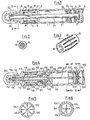
- the device shown in Figures 1 to 3 consists of a storage container 1 on one side in a Bearing neck 2 runs out, with which it is connected via an end wall 3.
- a support plate 4 and an end plug 5 is inserted in the open end of the storage container 1.
- a piston rod 7 is guided, which carries a support collar 8 at its rear end and has at least one axial channel 9 on the opposite side, which extends to a tip 10 which is used to apply the contained in the container 1 Mass serves.
- a plurality of axial channels 9 can also be formed in the piston rod 7.
- a sealing piston 12 is mounted on the piston rod 7, with which the storage container 1 is closed to the rear.
- the sealing piston 12 has a feed lamella 13 on the side facing the inside of the storage container 1 and a locking lamella 14 on the outer side.
- a front part 15 is mounted in a stationary manner at the front end of the piston rod 7. In the front part 15, a step 16 is formed, which corresponds to the diameter of the step 17, which is arranged on the storage container 1.
- the two stages 16; 17 serve to fasten a sleeve 18, which covers a switching ring 19 with lever arms 20. As strength of F.
- slots 21 are provided between the lever arms 20, the width of which is selected so that the lever arms 20 can be supported against one another regardless of the radial position of one of the two switching rings 19.
- the switching rings 19 are axially movable on the bearing neck 2, so that when the lever arms 20 are pressed, the switching ring 19 resting on the front part 15 can move axially.
- a closure cap 22 is known to be provided, which can be placed sealingly on the front part 15.
- the user In order to transport the flowable mass 23 from the storage container 1 to the tip 10 with the device, the user must press on the cuff 18 and thereby bring the lever arms 20 into an extended position in which they rest on the bearing neck 2. In this extended position of the lever arms 20, the front part 15 is pulled away from the bearing neck 2 together with the piston rod 7. During this movement, the sealing piston 12 follows the feed lamella 13 of the piston rod 7 and exerts pressure on the mass 23. The sealing piston 12 immediately follows the piston rod 7, since the feed lamella 13 expands, and prevents the sealing piston 12 from slipping on the piston rod 7. During the movement of the sealing piston 12, the mass 23 is pressed through one of the axial channels 9 to the tip 10 and can be applied from there.
- a mouthpiece 101 is inserted as a separate part, which merges into a bearing neck 102.
- a step 103 and a centering ring 104 formed on the mouthpiece serve to accommodate further parts.
- the container 100 is sealed on the back with a smooth surface by an end cap 105 which contains a vent hole 106.
- a piston rod 107 extends approximately over the entire length of the storage container 100 and is connected at its front end to a valve stem 108, over the entire length of which an axial channel 109 extends to the piston rod 107.
- the axial channel 109 is closed off by the piston rod 107, which is pressed into a receiving bore 110, but is guided outward into the region of a valve cone 112 by means of an overflow channel 111.
- an insertion bore 113 is provided, in which an application element 114 is fastened, which carries a distributor cap 114.1 on the front.
- a front part 115 is also fixedly attached to the valve stem 108, through which the application element 114, which has a dispensing opening 116, extends. It is also possible to dispense with the application element 114 and to mold the dispensing opening 116 directly into the front part 115.
- the front part 115 also has a step 117, which lies opposite the step 103 on the mouthpiece 101, and a sealing surface 118 for fitting a closure cap 132.
- Two switching rings 119 with lever arms 120 are attached to the bearing neck 102 and correspond to the switching rings 19 of FIG. 3. Not shown slots 121 between the lever arms 120 are - as in Fig. 3 - kept so narrow that - regardless of the radial position of the switching rings 119 - the lever arms 120 bear against one another at least partially
- a sealing piston 122 is provided, which rests on a locking piston 123.
- a feed lamella 124 and a lock lamella 125 sit on opposite end faces on the locking piston 123.
- the feed lamella 124 has inwardly open slots 124.1 which end in a bore 124.2. This bore 124.2 is kept smaller in diameter than the piston rod 107, so that it can only be placed there after arching of the feed lamella 124.
- the locking plate 125 on the other hand, has slots 125.1 which are open to the outside and end in the outer diameter 125.2. This outer diameter 125.2 is larger than the inner diameter of the storage container 100.
- a sealing membrane 127 is fixed to its inner diameter by means of a stop bushing 126, which is placed on the valve stem 108, against which a compression spring 128 also bears.
- the sealing membrane 127 is fastened to a connecting bushing 129 on the outside diameter.
- a valve seat 130 and a support ring 131 which presses the outer diameter of the sealing membrane 127 against the mouthpiece 101, are provided in this connecting bushing 129.
- a closure cap 132 is provided and an elastic sleeve 133 is placed over the switching ring 119, which is attached to the steps 103; 117 rests.
- This sleeve 133 is both axially and radially elastic and can thus follow the movement of the lever arms 120 and the front part 115.
- the function of the embodiment according to FIG. 4 is similar to the pure according to the embodiment of the F. 1.
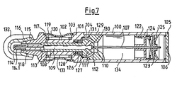
- the sleeve 133 In order to convey flowable mass 134 from the storage container 100 to the application element 114, the sleeve 133 must be compressed in the grip area, as a result of which the lever arms 120 rest against the bearing neck 102 in a known manner. This position can be seen from FIG. 7, which also shows that the front part 115 lifts off the bearing neck 102. With the front part 115, the valve stem 108 and the piston rod 107 are moved axially. With the piston rod 107, the locking piston 123 is simultaneously advanced, which is coupled to the piston rod 107 as a result of the feed lamella 124.
- valve cone 112 lifts off from the valve seat 130 and mass 134 is pressed out of the reservoir 100 by means of the sealing piston 122, which follows the movement of the locking piston. Since the space immediately behind the valve seat 130 is closed off by the sealing membrane 127, the mass 134 penetrates into the overflow channel 111 and is fed from there through the axial channel 109 and the discharge opening 116 to the application element 114. If the pressure on the cuff 133 and the lever arms 120 underneath decreases, the piston rod 107 is moved back into the starting position by means of the compression spring 128. A simultaneous return of the sealing piston 122 with the piston rod 107 is prevented by the locking piston 123, the outer locking plate of which is supported against the inner wall of the storage container 100.
- the respective metered quantity of the mass 134 is determined by the axial travel of the front part 115, which in turn is predetermined by the extended position of the lever arms 120.
- the lever arms 120 act in the manner of a toggle joint. For moving the lever arms 120 from the position shown in FIG. 4 into the position according to FIG. 7 due to the lever ratio, a much smaller force is required than the force acting on the sealing piston 122.
- the lever arms 120 thus serve as a transmission mechanism and have the advantage that, with the device being easy to operate, an exact metering of the smallest quantities of the mass 134 to be dispensed is possible.
Landscapes
- Engineering & Computer Science (AREA)
- Mechanical Engineering (AREA)
- Containers And Packaging Bodies Having A Special Means To Remove Contents (AREA)
- Coating Apparatus (AREA)
Applications Claiming Priority (2)
| Application Number | Priority Date | Filing Date | Title |
|---|---|---|---|
| DE19863609020 DE3609020A1 (de) | 1986-03-18 | 1986-03-18 | Vorrichtung zum auftragen von fliessfaehigen massen |
| DE3609020 | 1986-03-18 |
Publications (1)
| Publication Number | Publication Date |
|---|---|
| EP0240738A2 true EP0240738A2 (fr) | 1987-10-14 |
Family
ID=6296660
Family Applications (1)
| Application Number | Title | Priority Date | Filing Date |
|---|---|---|---|
| EP19870103223 Withdrawn EP0240738A2 (fr) | 1986-03-18 | 1987-03-06 | Dispositif pour appliquer des masses capables de couler |
Country Status (5)
| Country | Link |
|---|---|
| EP (1) | EP0240738A2 (fr) |
| JP (1) | JPS62227466A (fr) |
| BR (1) | BR8701189A (fr) |
| DE (1) | DE3609020A1 (fr) |
| PT (1) | PT84028A (fr) |
Cited By (2)
| Publication number | Priority date | Publication date | Assignee | Title |
|---|---|---|---|---|
| EP0420047A3 (en) * | 1989-09-23 | 1991-11-06 | Otto Katz | Device for the metered delivery or the application of liquid or pasty products |
| EP3575102A1 (fr) * | 2018-05-28 | 2019-12-04 | Georg Linz Fabrik moderner Schreibgeräte GmbH & Co. KG | Appareil d'application |
Families Citing this family (2)
| Publication number | Priority date | Publication date | Assignee | Title |
|---|---|---|---|---|
| DE8907135U1 (de) * | 1989-06-10 | 1990-10-11 | Rotring-Werke Riepe Kg, 2000 Hamburg | Auftragsvorrichtung für flüssiges oder pastöses Gut, insbesondere Nagellack |
| DE9210904U1 (de) * | 1992-08-14 | 1992-11-12 | Schneider, Friedhelm, 5226 Reichshof | Dosierpistolen für Schlauchbeutel mit Spreizscheiben und hydraulischer Betätigung |
Family Cites Families (3)
| Publication number | Priority date | Publication date | Assignee | Title |
|---|---|---|---|---|
| US4033700A (en) * | 1976-02-02 | 1977-07-05 | Spatz Corporation | Dispenser for fluent material |
| DE2945338A1 (de) * | 1979-11-09 | 1981-05-21 | Joachim 8405 Donaustauf Czech | Spender fuer pastoese produkte |
| DE3214706A1 (de) * | 1981-05-21 | 1982-12-09 | Hans 6200 Wiesbaden Orth | In der hand zu haltendes schreibgeraet, insbesondere kugelschreiber |
-
1986
- 1986-03-18 DE DE19863609020 patent/DE3609020A1/de not_active Withdrawn
- 1986-12-29 PT PT8402886A patent/PT84028A/pt not_active Application Discontinuation
-
1987
- 1987-03-06 EP EP19870103223 patent/EP0240738A2/fr not_active Withdrawn
- 1987-03-16 BR BR8701189A patent/BR8701189A/pt unknown
- 1987-03-18 JP JP6142587A patent/JPS62227466A/ja active Pending
Cited By (2)
| Publication number | Priority date | Publication date | Assignee | Title |
|---|---|---|---|---|
| EP0420047A3 (en) * | 1989-09-23 | 1991-11-06 | Otto Katz | Device for the metered delivery or the application of liquid or pasty products |
| EP3575102A1 (fr) * | 2018-05-28 | 2019-12-04 | Georg Linz Fabrik moderner Schreibgeräte GmbH & Co. KG | Appareil d'application |
Also Published As
| Publication number | Publication date |
|---|---|
| PT84028A (pt) | 1987-08-19 |
| JPS62227466A (ja) | 1987-10-06 |
| BR8701189A (pt) | 1988-01-19 |
| DE3609020A1 (de) | 1987-10-01 |
Similar Documents
| Publication | Publication Date | Title |
|---|---|---|
| DE69003405T2 (de) | Spender mit einem verschiebbaren Kolben. | |
| EP0084638B1 (fr) | Distributeur pour produits pâteux | |
| EP0036491B1 (fr) | Distributeur pour produits pâteux | |
| DE19910972C1 (de) | Vorrichtung zum Auftragen eines fließfähigen Mediums, insbesondere eines Gewebeklebstoffs | |
| EP1173078B1 (fr) | Distributeur de creme et de deodorant | |
| WO2007121854A2 (fr) | Applicateur à récipient interchangeable | |
| EP0053329B1 (fr) | Récipient pour distribuer en portions un produit de consistance pâteuse | |
| EP1170061A2 (fr) | Distributeur de fluides | |
| EP0284907B1 (fr) | Distributeur de produits visqueux | |
| DE3124586C2 (fr) | ||
| DE20019091U1 (de) | Vorab gefüllte, teleskopartig zusammenschiebbare Ampulle | |
| EP0347546A2 (fr) | Distributeur pour produits pâteux | |
| DE102016207722A1 (de) | Flüssigkeitsspender | |
| EP0691284B1 (fr) | Distributeur pour masses pâteuses | |
| DE3629627C1 (de) | Stiftfoermige Vorrichtung zum Abgeben von fliessfaehigen Massen aus einem Vorratsbehaelter | |
| EP0315077A1 (fr) | Distributeur pour produits pâteux | |
| EP0258799A2 (fr) | Dispositif en forme de crayon pour dispenser des masses fluides | |
| EP0240738A2 (fr) | Dispositif pour appliquer des masses capables de couler | |
| DE3538001C2 (fr) | ||
| DE3520523C2 (fr) | ||
| DE8816917U1 (de) | Spender für pastöse Massen | |
| DE19921662B4 (de) | Creme- und Deospender | |
| WO1990004340A1 (fr) | Systeme de distribution pour substances fluides | |
| DE3701180C2 (fr) | ||
| DE3421823A1 (de) | Mehrkomponenten-kartusche |
Legal Events
| Date | Code | Title | Description |
|---|---|---|---|
| PUAI | Public reference made under article 153(3) epc to a published international application that has entered the european phase |
Free format text: ORIGINAL CODE: 0009012 |
|
| AK | Designated contracting states |
Kind code of ref document: A2 Designated state(s): AT BE CH DE ES FR GB GR IT LI LU NL SE |
|
| STAA | Information on the status of an ep patent application or granted ep patent |
Free format text: STATUS: THE APPLICATION HAS BEEN WITHDRAWN |
|
| 18W | Application withdrawn |
Withdrawal date: 19880210 |
|
| RIN1 | Information on inventor provided before grant (corrected) |
Inventor name: KATZ, OTTO |