EP0240712B1 - Trailer for passenger cars - Google Patents
Trailer for passenger cars Download PDFInfo
- Publication number
- EP0240712B1 EP0240712B1 EP19870102996 EP87102996A EP0240712B1 EP 0240712 B1 EP0240712 B1 EP 0240712B1 EP 19870102996 EP19870102996 EP 19870102996 EP 87102996 A EP87102996 A EP 87102996A EP 0240712 B1 EP0240712 B1 EP 0240712B1
- Authority
- EP
- European Patent Office
- Prior art keywords
- wall
- floor
- trailer according
- channel
- tail
- Prior art date
- Legal status (The legal status is an assumption and is not a legal conclusion. Google has not performed a legal analysis and makes no representation as to the accuracy of the status listed.)
- Expired - Lifetime
Links
Images


Classifications
-
- B—PERFORMING OPERATIONS; TRANSPORTING
- B62—LAND VEHICLES FOR TRAVELLING OTHERWISE THAN ON RAILS
- B62D—MOTOR VEHICLES; TRAILERS
- B62D63/00—Motor vehicles or trailers not otherwise provided for
- B62D63/06—Trailers
- B62D63/062—Trailers with one axle or two wheels
Definitions
- the invention relates to a trailer for passenger cars with a body that has a rectangular bottom and rising from the bottom edges, consisting of one piece of side walls, the side walls (side walls) and at least one transverse side wall (cross wall) directly with are screwed to the bottom and the whole from the bottom.
- the side walls and transverse wall form a self-supporting unit without the use of side members.
- a trailer of this type has a self-supporting box, since the side walls form stable longitudinal members and a great torsional rigidity is achieved by connecting the side wall to the floor and the side walls. This significantly reduces the manufacturing costs and the unladen weight.
- the side walls are made of extruded aluminum profiles. Such profiles are relatively expensive.
- the invention has for its object to design a trailer of the type mentioned in such a way that it is cheaper to manufacture, with a particularly great robustness to be achieved.
- the side walls consist of one-piece profiles made of galvanized sheet steel, each side wall having a channel along its upper and lower edge and the middle side wall area lying between the channels is single-walled, the channels also being provided by a Overlap of the sheet are closed, a connection between the sheet layers lying on top of one another is provided in the overlap area and an offset of the profile is provided at the edge of the overlap area approximately by the thickness of the steel sheet, which overlaps the edge of the sheet.
- Steel sheet profiles can be manufactured relatively cheaply if mass-produced accordingly. Such profiles are extremely robust.
- the trailer according to the invention is therefore particularly suitable for rough operation, e.g. also for the transport of building materials and the like.
- the drop sides are particularly stable because channels are formed from the sheet steel along the upper and lower edges, while the intermediate drop area can be single-walled.
- This design is also particularly advantageous in more static terms, since the side wall, like an I-beam, has an upper chord, a lower chord and a web in between. This design is also favorable for use because the side walls are relatively wide at their upper edges.
- the middle side wall area is preferably reinforced by means of longitudinal beads. These beads preferably have a trapezoidal cross section.
- the channels of the side walls are closed by an overlap of the sheet metal, a connection being preferably provided in the overlap area, which can be produced in particular by spot welding.
- An offset is provided in the overlap area, as a result of which the undesired protrusion of a sheet edge is avoided and the stiffness of the profile is additionally increased.
- a fold for gripping around the associated bottom edge is preferably provided on the lower edge of each side wall.
- a wall of the fold is achieved by doubling the profile sheet.
- Push-through screws are preferably arranged for the connection between the floor and the side walls. In contrast to the known construction mentioned at the outset, these screws are passed through individual holes in the side wall, while a continuous slot is provided for this in the known construction with extruded profiles.
- the channels have parallel channel side walls that are parallel to the general side wall level, and the upper channel has an upper and the lower channel a lower channel wall that are perpendicular to the general side wall level, and if the upper channel wall and the an inclined duct wall opposite the lower duct wall, which encloses an obtuse angle with the outer duct side wall.
- the channels can be reduced to a smaller width at their ends, the reduced area being encompassed by corner profiles. This enables the use of the same corner profiles also for trailers whose side walls consist of extruded aluminum profiles that are thinner than the channels of the side walls made of steel profiles according to the present invention. In terms of deformation technology, it is unproblematic to reduce the width of steel side walls, while this is hardly possible with aluminum extrusion profiles
- filler plates are provided in the corner areas, which are attached to a wall Fitting corner profiles that connect side walls that are perpendicular to one another and are adapted with the end edge of a further wall to the outer contour of the side walls.
- Relatively thin sheet metal is sufficient for the drop sides.
- a sheet thickness of 1.25 mm is particularly useful.
- the trailer has a body 1, a chassis 2 and a drawbar 3.
- the body consists of a floor 4, two side walls 5a and 5b, a fixed front wall 6 and a hinged rear wall 7.
- the structure of the body should be considered.
- All walls 5a, 5b, 6, 7 have the same profile, which is shown in Fig. 4. All walls 5a, 5b, 6, 7 are made of galvanized sheet steel.
- the profile has an upper channel 8, a lower channel 9 and a single-walled intermediate area 10. Sections 11 to 33 can be distinguished on the profile. The profile is described in detail below using the profile sections entered in FIG. 4.
- the profile section 11 merges into a horizontal profile section 12 via a right-angled bevel 34. This passes again via a right-angled bend 35 into the profile section 13, which is parallel to the profile section 11.
- the profile section 13 merges into the profile section 14 via an obtuse-angled bend 36, which in turn merges into the profile section 14 via an obtuse-angled bend 37.
- the profile section 14 is parallel to the lower edge region of the profile section 11.
- the profile sections are in this area without a gap.
- the profile section 15 merges into a very short profile section 16 via a bevel 38, which opens into the profile section 17 via a further bevel 39.
- the bevels 38, 39 and the profile section 16 form an offset by the thickness s of the sheet from which the profile is made.
- the profile section 26 is again part of an offset by the sheet thickness.
- the profile section 27 merges again via an obtuse-angled bend 42 into the profile section 28, which merges into the profile section 29 via a further obtuse-angled bend 43.
- the profile sections 29, 31 merge into one another via a 180 ° bend 44, while the profile section 32 adjoins the profile section 31 via a right-angled bend 45.
- the profile section 33 which is parallel to the profile section 29, adjoins this via a right-angled bend 46.
- the upper edge region of the profile section 33 lies against the profile section 27 without a gap.
- the areas of the sheet metal lying against one another without a gap are welded to one another via spot welds 47, 48, 49.
- the adjacent sections 11 and 15 are also connected to one another by spot welds 50.
- the profile sections 31 and 32 together form a fold of the width s2 for the engagement of the bottom 4, which has the thickness s3.
- the width of channels 8 and 9, measured on the outside, is denoted by s1.
- the thickness s of the sheet is preferably 1.25 mm.
- the bottom 4 is connected to the side walls 5a and 5b and to the front transverse wall 6 by screws 51.
- Each screw 51 passes through a through hole 52 in the bottom 4 and a through hole 53 in the lower wall 32 of the lower channel 9.
- an insert 54 is provided, which in turn has a through hole 55.
- the recess is hexagonal, so that the hexagonal nut 57 is held in the insert 54 in a non-rotatable manner.
- the screws 51 are cap screws, e.g. with a hexagon head 51a.
- a spring ring 58 and a washer 59 are arranged on each screw between the screw head 51a and the base 4. This prevents the screw from loosening and prevents the base 4 from being damaged by the washer 59.
- the bottom 4 advantageously consists of a larger number of layers of wood glued together.
- the top 4a is roughened to make the floor non-slip.
- the base is preferably coated with a synthetic resin, preferably phenolic resin.
- Posts 60 are arranged at the front corners of the car body 1 and posts 61 are arranged at the rear corners (see FIG. 2), the cross sections of which can be seen in FIG. 3.
- the posts 60 are hollow profiles with a cavity 62.
- Ribs 63, 64 and 65, 66 protrude from the box-shaped part of the post containing the cavity 62.
- the pairs of ribs 63/64 and 65/66 embrace the ends of the drop sides.
- the side walls are deformed at their ends by squeezing so that the channels 8, 9 have a width s4 in their end regions, which is less than the full width s1 of the channels.
- the clear distance between pairs of ribs 63/64 or 65/66 is such that the ends of the channels can be inserted between the ribs. It is thereby possible to use the same post profiles, regardless of whether the side walls are made of extruded aluminum profiles that are narrower than the width s 1 of the channels 8, 9 or whether side walls are used according to the present
- Angular filler plates 67 are provided to seal the car body in the corner areas.
- the filler plates have a leg 67a which is connected to the rib 64, for which the same rivets 68 are used, with which the rib 64 is also connected to the side wall 6.
- a second leg 67b has such a configuration of its edge 67 ⁇ b that it adapts to the external unevenness of the side wall, namely to the beads 40, 41. This adjustment can be seen in Fig. 1.
- FIG. 5 shows how the rear wall 5b of the car body is held by means of fittings 72.
- the fittings 72 have a joint 73 and are fastened to both the underside of the box bottom 4 and to the rear wall 5b, specifically on the outer wall 29 of the lower channel 9.
- Filling plates are also on the rear wall 67 provided. 5 also shows the adaptation of the filler plates to the beads. A corresponding cutout 74 in the filler plate can be seen.
- the traverse 75 has a horizontal wall 75a, which bears against the underside of the box bottom 4, a vertical wall 75c, which projects downward from the box bottom 4, and a wall 75d, which adjoins the wall 75c at an obtuse angle and projects rearward. To avoid a sharp edge, a rounding is formed at the end of the wall 75d by bending the sheet.
- the cross member is also penetrated by screws 51, so that the cross member is also connected to the side walls 5a, 5b with these screws.
- Triangular plates 77 which are connected to the vertical wall 75c by rivets 87, serve to brace the crossmember in relation to the body.
- the traverse 75 also serves as a support for rear lights 76 and for a license plate.
- the chassis 2 has an axis designated 78 in total.
- the axis 78 has a tube 79 which extends below the body 1.
- Swing arms 80 are mounted in the tube 79 and are cushioned relative to the tube 79.
- Wheels 81 are located at the ends of the swing arms 78.
- the axle 78 is connected to the body 1 by means of axle brackets 82.
- FIG. 6 shows an embodiment in which each axle bracket 82 is welded directly to the tube 79 (weld seam 83).
- the axle bracket 82 has an upper horizontal flange 84 which bears against the underside 4b of the body 4.
- the flange 84 is penetrated by a screw 51 which is screwed into the side wall 5b in the same way as was explained with reference to FIG. 4 and which is accordingly also effective as a floor fastening screw.
- the mounting flange 84 is relatively long. Its length 11 (see Fig. 1) is at least 150 mm. This provides a favorable introduction of the supporting forces into the walls 5a and 5b.
- the axle bracket designed as a Z-profile, which is formed by folding a sheet.
- the axle bracket has an upper flange 82 ⁇ a, which is screwed to the body 1 and a lower flange 82 ⁇ b.
- a sheet metal 85 is welded to the axle tube 79 ⁇ and has an upper horizontal leg 85a, which bears against the leg 82 ⁇ b of the axle bracket 82 ⁇ and is screwed to it by means of screws 86.
- the axle bracket 82 ⁇ is fastened by means of a screw 51, with which the wall 5b is also fastened to the box bottom 4.
- the embodiment according to FIG. 8 differs from the embodiment according to FIG. 7 in that the axle bracket 82 ⁇ is shorter than the axle bracket 82 ⁇ according to FIG. 7. In both cases, the axles are Z-shaped sheets.
- the construction according to FIGS. 7 and 8 has the advantage that the height of the trailer can be changed comfortably. Either axles with flanges 85a, 85 ⁇ a at different heights can be used, or the axles can be made uniform and the axles 82 ⁇ , 82 ⁇ modified accordingly. Both variants are shown together in the drawing.
Description
Die Erfindung bezieht sich auf einen Anhänger für Personenkraftwagen mit einem Wagenkasten, der einen rechteckigen Boden und von den Bodenkanten sich erhebende, aus einem Stück bestehende Bordwände aufweist, wobei die seitlichen Bordwände (Seitenwände) und mindestens eine quer dazu verlaufende Bordwand (Querwand) unmittelbar mit dem Boden verschraubt sind und die Gesamtheit aus Boden. Seitenwänden und Querwand unter Verzicht auf Längsträger eine selbsttragende Einheit bilden.The invention relates to a trailer for passenger cars with a body that has a rectangular bottom and rising from the bottom edges, consisting of one piece of side walls, the side walls (side walls) and at least one transverse side wall (cross wall) directly with are screwed to the bottom and the whole from the bottom. The side walls and transverse wall form a self-supporting unit without the use of side members.
Ein Anhänger dieser Art hat einen selbsttragenden Kasten, da die Bordwände stabile Längsträger bilden und durch die Verbindung der Bordwand mit dem Boden und der Bordwände untereinander auch eine große Verwindungssteifigkeit erzielt wird. Dadurch lassen sich die Herstellungskosten und das Leergewicht wesentlich herabsetzen Bei einem bekannten Anhänger dieser Art (DE-A1 32 29 062) bestehen die Bordwände aus Aluminium-Strangpreßprofilen. Solche Profile sind relativ teuer.A trailer of this type has a self-supporting box, since the side walls form stable longitudinal members and a great torsional rigidity is achieved by connecting the side wall to the floor and the side walls. This significantly reduces the manufacturing costs and the unladen weight. In a known trailer of this type (DE-A1 32 29 062), the side walls are made of extruded aluminum profiles. Such profiles are relatively expensive.
Der Erfindung liegt die Aufgabe zugrunde, einen Anhänger der eingangs genannten Art so auszubilden, daß er billiger herstellbar ist, wobei eine besonders große Robustheit erreicht werden soll.The invention has for its object to design a trailer of the type mentioned in such a way that it is cheaper to manufacture, with a particularly great robustness to be achieved.
Diese Aufgabe wird nach der Erfindung dadurch gelöst, daß die Bordwände aus einteiligen Profilen aus verzinktem Stahlblech bestehen, wobei jede Bordwand längs ihrem oberen und ihrem unteren Rand einen Kanal aufweist und der zwischen den Kanälen liegende mittlere Bordwandbereich einwandig ist, wobei ferner die Kanäle durch eine Überlappung des Bleches geschlossen sind, im Überlappungsbereich eine Verbindung zwischen den aufeinanderliegenden Blechlagen vorgesehen ist und am Rand des Überlappungsbereiches eine Verkröpfung des Profiles etwa um die Dicke des Stahlbleches vorgesehen ist, die den Rand des Blechen übergreift.This object is achieved according to the invention in that the side walls consist of one-piece profiles made of galvanized sheet steel, each side wall having a channel along its upper and lower edge and the middle side wall area lying between the channels is single-walled, the channels also being provided by a Overlap of the sheet are closed, a connection between the sheet layers lying on top of one another is provided in the overlap area and an offset of the profile is provided at the edge of the overlap area approximately by the thickness of the steel sheet, which overlaps the edge of the sheet.
Profile aus Stahlblech lassen sich bei entsprechender Massenproduktion relativ billig herstellen. Solche Profile sind außerordentlich robust. Der erfindungsgemäße Anhänger ist deshalb besonders für rauhen Betrieb geeignet, z.B. auch für den Transport von Baumaterialien und dergleichen.Steel sheet profiles can be manufactured relatively cheaply if mass-produced accordingly. Such profiles are extremely robust. The trailer according to the invention is therefore particularly suitable for rough operation, e.g. also for the transport of building materials and the like.
Besonders stabil werden die Bordwände, weil längs dem oberen und dem unteren Rand Kanäle aus dem Stahlblech geformt werden, während der dazwischenliegende Bordwandbereich einwandig sein kann. Diese Ausbildung ist auch in statischere Hinsicht besonders vorteilhaft, da die Bordwand, ähnlich einem I-Träger, einen Obergurt, einen Untergurt und dazwischenliegend einen Steg aufweist. Auch für den Gebrauch ist diese Formgestaltung günstig, da die Bordwände an ihren oberen Rändern relativ breit sind.The drop sides are particularly stable because channels are formed from the sheet steel along the upper and lower edges, while the intermediate drop area can be single-walled. This design is also particularly advantageous in more static terms, since the side wall, like an I-beam, has an upper chord, a lower chord and a web in between. This design is also favorable for use because the side walls are relatively wide at their upper edges.
Der mittlere Bordwandbereich ist vorzugsweise mittels Längssicken verstärkt. Diese Sicken haben vorzugsweise einen trapezförmigen Querschnitt.The middle side wall area is preferably reinforced by means of longitudinal beads. These beads preferably have a trapezoidal cross section.
Die Kanäle der Bordwände sind durch eine Überlappung des Bleches geschlossen, wobei im Überlappungsbereich vorzugsweise auch eine Verbindung vorgesehen ist, die insbesondere durch Punktschweißungen hergestellt werden kann. Im Überlappungsbereich ist eine Verkröpfung vorgesehen, wodurch das unerwünschte Vorstehen einer Blechkante vermieden wird und zusätzlich die Steifigkeit des Profiles erhöht wird.The channels of the side walls are closed by an overlap of the sheet metal, a connection being preferably provided in the overlap area, which can be produced in particular by spot welding. An offset is provided in the overlap area, as a result of which the undesired protrusion of a sheet edge is avoided and the stiffness of the profile is additionally increased.
Aus der FR-Patentschrift 89 565 ist es zwar bereits bekannt, Kanäle der o.a. Art vorzusehen; sie sind mit glatt auf das Profil gepunkteten Laschen geschlossen, was dazu führt, daß die Innenwände eines solchen Anhängers nicht glatt sind, so daß beim Be- und Entladen erhebliche Schwierigkeiten auftreten können. Der erfindungsgemäße Anhänger weist einen solchen Nachteil nicht auf: die Bordwände sind innen ganz glatt.From FR patent specification 89 565 it is already known that channels of the above. Type to provide; they are closed with tabs smoothly dotted on the profile, which means that the inner walls of such a trailer are not smooth, so that considerable difficulties can arise during loading and unloading. The trailer according to the invention does not have such a disadvantage: the inside of the side walls are completely smooth.
Vorzugsweise ist am unteren Rand jeder Bordwand ein Falz zum Umgreifen des zugeordneten Bodenrandes vorgesehen. Eine Wand des Falzes wird hierbei erfindungsgemäß durch eine Doppelung des Profilbleches erzielt. Zur Verbindung zwischen Boden und Bordwänden werden vorzugsweise Durchsteckschrauben angeordnet. Im Gegensatz zu der eingangs erwähnten bekannten Konstruktion werden diese Schrauben durch einzelne Löcher in der Bordwand hindurchgeführt, während bei der bekannten Konstruktion mit Strangpreßprofilen hierfür ein durchgehender Schlitz vorgesehen ist. Durch die Verwendung von Druckstücken wird einmal eine gute Einleitung der Schraubenkräfte in die Bordwand erzielt und zum anderen auch dieA fold for gripping around the associated bottom edge is preferably provided on the lower edge of each side wall. According to the invention, a wall of the fold is achieved by doubling the profile sheet. Push-through screws are preferably arranged for the connection between the floor and the side walls. In contrast to the known construction mentioned at the outset, these screws are passed through individual holes in the side wall, while a continuous slot is provided for this in the known construction with extruded profiles. Through the use of pressure pieces, a good introduction of the screw forces into the side wall is achieved, on the one hand, and the other
Montage erleichtert, wenn die Muttern undrehbar in dem Druckstück gehalten sind, wie dies vorzugsweise der Fall sein soll.Assembly easier if the nuts are held in the pressure piece in a non-rotatable manner, as is preferably the case.
Es ist vorteilhaft, die Innenseiten der Bordwände im wesentlichen eben auszubilden, da dadurch das Beladen des Kastens erleichtert wird. Dies wird durch Anordnung der Kanäle an den Außenseiten der Bordwände erreicht.It is advantageous to make the inside of the side walls essentially flat, since this makes loading the box easier. This is achieved by arranging the channels on the outside of the side walls.
Besonders vorteilhaft ist es, wenn die Kanäle parallele Kanal-Seitenwände haben, die parallel zur allgemeinen Bordwandebene sind, und der obere Kanal eine obere und der untere Kanal eine untere Kanalwand aufweisen, die rechtwinklig zur allgemeinen Bordwandebene verlaufen, und wenn der oberen Kanalwand und der unteren Kanalwand jeweils eine schräge Kanalwand gegenüberliegt, die mit der äußeren Kanal-Seitenwand einen stumpfen Winkel einschließt. Man erhält dadurch eine obere ebene Endfläche und durch die schrägen Kanalwände eine gute Einleitung von Kräften in den Wandbereich, der zwischen den Kanälen liegt.It is particularly advantageous if the channels have parallel channel side walls that are parallel to the general side wall level, and the upper channel has an upper and the lower channel a lower channel wall that are perpendicular to the general side wall level, and if the upper channel wall and the an inclined duct wall opposite the lower duct wall, which encloses an obtuse angle with the outer duct side wall. This gives an upper flat end face and the inclined channel walls ensure good introduction of forces into the wall area that lies between the channels.
Die Kanäle können an ihren Enden auf eine geringere Breite reduziert sein, wobei der reduzierte Bereich von Eckprofilen umgriffen ist. Dies ermöglicht die Verwendung gleicher Eckprofile auch für Anhänger, deren Bordwände aus Aluminium-Strangpreßprofilen bestehen, die dünner sind als die Kanäle der Bordwände aus Stahlprofilen gemäß der vorliegenden Erfindung. Verformungstechnisch ist es unproblematisch, Stahl-Bordwände in der Breite zu reduzieren, während dies bei Aluminium-Strangpreßprofilen kaum möglich istThe channels can be reduced to a smaller width at their ends, the reduced area being encompassed by corner profiles. This enables the use of the same corner profiles also for trailers whose side walls consist of extruded aluminum profiles that are thinner than the channels of the side walls made of steel profiles according to the present invention. In terms of deformation technology, it is unproblematic to reduce the width of steel side walls, while this is hardly possible with aluminum extrusion profiles
Gemäß einer weiteren Ausgestaltung sind in den Eckbereichen Füllbleche vorgesehen, die mit einer Wand an Eckprofilen anliegen, die rechtwinklig zueinander stehende Bordwände verbinden und mit der Endkante einer weiteren Wand an die Außenkontur der Bordwände angepaßt sind. Dadurch erreicht man eine Abdichtung in den Eckbereichen des Wagenkastens auch dann, wenn die Bordwände stark profiliert sind.According to a further embodiment, filler plates are provided in the corner areas, which are attached to a wall Fitting corner profiles that connect side walls that are perpendicular to one another and are adapted with the end edge of a further wall to the outer contour of the side walls. As a result, a seal is achieved in the corner areas of the car body even if the side walls are strongly profiled.
Für die Bordwände genügt relativ dünnes Blech. Besonders zweckmäßig ist eine Blechdicke von 1,25 mm.Relatively thin sheet metal is sufficient for the drop sides. A sheet thickness of 1.25 mm is particularly useful.
In der Zeichnung ist ein Ausführungsbeispiel der Erfindung dargestellt. Es zeigen:
- Fig. 1
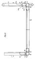
- eine Seitenansicht eines Anhängers entsprechend dem Pfeil I in Fig. 2,
- Fig. 2
- einen Grundriß des Anhängers entsprechend dem Pfeil II in Fig. 1 in einem gegenüber Fig. 1 verkleinerten Maßstab,
- Fig. 3
- einen teilweisen Horizontalschnitt nach Linie III-III in einem gegenüber Fig. 1 vergrößerten Maßstab,
- Fig. 4
- einen teilweisen Vertikalschnitt nach Linie IV-IV in Fig. 1, jedoch in einer gegenüber Fig. 1 vergrößerten Darstellung und ergänzt zu einer perspektivischen Zeichnung,
- Fig. 5
- einen Vertikalschnitt im hinteren Bereich des Wagenkastens entsprechend der Linie V-V in Fig. 2,
- Fig. 6
- einen teilweise Vertikalschnitt im Bereich der Achsaufhängung entsprechend der Linie VI-VI in Fig. 1 und
- Fig. 7 und 8
- Vertikalschnitte entsprechend Fig. 6 bei anderen Ausführungsformen der Erfindung.
- Fig. 1
- a side view of a trailer according to the arrow I in Fig. 2,
- Fig. 2
- 2 shows a plan view of the trailer according to arrow II in FIG. 1 on a smaller scale than in FIG. 1,
- Fig. 3
- 2 shows a partial horizontal section along line III-III on an enlarged scale compared to FIG. 1,
- Fig. 4
- 2 shows a partial vertical section along line IV-IV in FIG. 1, but in an enlarged view compared to FIG. 1 and supplemented to a perspective drawing,
- Fig. 5
- a vertical section in the rear area of the car body along the line VV in Fig. 2,
- Fig. 6
- a partial vertical section in the region of the axle suspension along the line VI-VI in Fig. 1 and
- 7 and 8
- 6 in other embodiments of the invention.
Der Anhänger hat einen Wagenkasten 1, ein Fahrgestell 2 und eine Deichsel 3. Der Wagenkasten besteht aus einem Boden 4, zwei Seitenwänden 5a und 5b, einer fest angeordneten Vorderwand 6 und einer abklappbaren Rückwand 7. Zunächst soll der Aufbau des Wagenkastens betrachtet werden.The trailer has a
Alle Wände 5a, 5b, 6, 7 haben das gleiche Profil, das in Fig. 4 dargestellt ist. Alle Wände 5a, 5b, 6, 7 sind aus verzinktem Stahlblech hergestellt. Das Profil hat einen oberen Kanal 8, einen unteren Kanal 9 und einen einwandigen Zwischenbereich 10. An dem Profil lassen sich Abschnitte 11 bis 33 unterscheiden. Unter Heranziehung der in Fig. 4 eingetragenen Profilabschnitte wird das Profil nachfolgend im einzelnen beschrieben.All
Der Profilabschnitt 11 geht über eine rechtwinklige Abkantung 34 in den horizontalen Profilabschnitt 12 über. Dieser geht wieder über eine rechtwinklige Abkantung 35 in den Profilabschnitt 13 über, der zum Profilabschnitt 11 parallel ist. Der Profilabschnitt 13 geht über eine stumpfwinklige Abkantung 36 in den Profilabschnitt 14 über, der seinerseits über eine stumpfwinklige Abkantung 37 in den Profilabschnitt 14 übergeht. Der Profilabschnitt 14 ist zum unteren Randbereich des Profilabschnittes 11 parallel. Die Profilabschnitte liegen in diesem Bereich ohne Abstand aneinander. Der Profilabschnitt 15 geht über eine Abkantung 38 in den sehr kurzen Profilabschnitt 16 über, der über eine weitere Abkantung 39 in den Profilabschnitt 17 einmündet. Die Abkantungen 38, 39 und der Profilabschnitt 16 bilden eine Verkröpfung um die Dicke s des Bleches, aus dem das Profil hergestellt ist. Die Profilabschnitte 18, 19, 20, die jeweils über stumpfwinklige Abkantungen ineinander übergehen, bilden eine obere Längssicke 40 von trapezförmigem Querschnitt. Eine dazu parallele untere Längssicke 41, die den gleichen Querschnitt hat wie die Dicke 40, besteht aus den Profilabschnitten 22, 23, 24.The
Der Profilabschnitt 26 ist wieder Bestandteil einer Verkröpfung um die Blechdicke. Der Profilabschnitt 27 geht wieder über eine stumpfwinklige Abkantung 42 in den Profilabschnitt 28 über, der über eine weitere stumpfwinklige Abkantung 43 in den Profilabschnitt 29 übergeht. Die Profilabschnitte 29, 31 gehen über eine 180°-Abkantung 44 ineinander über, während an den Profilabschnitt 31 über eine rechtwinklige Abkantung 45 der Profilabschnitt 32 anschließt. An diesen schließt über eine rechtwinklige Abkantung 46 der Profilabschnitt 33 an, der zum Profilabschnitt 29 parallel ist. Der obere Randbereich des Profilabschnittes 33 liegt ohne Abstand am Profilabschnitt 27 an. Die ohne Abstand aneinanderliegenden Bereiche des Bleches sind über Punktschweißungen 47, 48, 49 miteinander verschweißt. Ebenfalls sind die aneinanderliegenden Abschnitte 11 und 15 durch Punktschweißungen 50 miteinander verbunden.The
Die Profilabschnitte 31 und 32 bilden zusammen einen Falz von der Breite s₂ für den Eingriff des Bodens 4, der die Dicke s₃ hat. Die Breite der Kanäle 8 und 9, gemessen an ihrer Außenseite, ist mit s₁ bezeichnet. Die Dicke s des Bleches beträgt vorzugsweise 1,25 mm.The
Der Boden 4 ist mit den Seitenwänden 5a und 5b und mit der vorderen Querwand 6 durch Schrauben 51 verbunden. Jede Schraube 51 durchgreift ein Durchgangsloch 52 im Boden 4 und ein Durchgangsloch 53 in der unteren Wand 32 des unteren Kanales 9. Im Kanal 9 ist (siehe dazu z.B. auch Fig. 6) ein Einlegestück 54 vorgesehen, das seinerseits ein Durchgangsloch 55 aufweist. In jedem Einlegestück 54 befindet sich eine Vertiefung 56 für die Aufnahme einer Schraubenmutter 57. Die Vertiefung ist sechskantig, so daß die sechskantige Mutter 57 undrehbar in dem Einlegestück 54 gehalten ist.The
Die Schrauben 51 sind Kopfschrauben, z.B. mit einem Sechskantkopf 51a. Zwischen dem Schraubenkopf 51a und dem Boden 4 ist an jeder Schraube ein Federring 58 und eine Unterlegscheibe 59 angeordnet. Dadurch wird ein Losdrehen der Schraube verhindert und durch die Unterlegscheibe 59 eine Beschädigung des Bodens 4 vermieden.The
Der Boden 4 besteht vorteilhafterweise aus einer größeren Zahl von miteinander verleimten Holzschichten. Die Oberseite 4a ist aufgerauht, um dem Boden rutschfest zu machen. Vorzugsweise ist der Boden mit einem Kunstharz, vorzugsweise Phenol-Harz, beschichtet.The bottom 4 advantageously consists of a larger number of layers of wood glued together. The top 4a is roughened to make the floor non-slip. The base is preferably coated with a synthetic resin, preferably phenolic resin.
An den vorderen Ecken des Wagenkastens 1 sind Pfosten 60 und an den hinteren Ecken Pfosten 61 angeordnet (siehe Fig.2), deren Querschnitte aus Fig. 3 ersichtlich sind. Die Pfosten 60 sind Hohlprofile mit einer Höhlung 62. Von dem kastenförmigen, die Höhlung 62 enthaltenden Teil des Pfostens ragen Rippen 63, 64 bzw. 65, 66 ab. Die Rippenpaare 63/64 und 65/66 umfassen die Enden der Bordwände. Die Bordwände sind an ihren Enden durch Verquetschen so verformt, daß die Kanäle 8, 9 in ihren Endbereichen eine Breite s₄ aufweisen, die geringer ist als die volle Breite s₁ der Kanäle. Der lichte Abstand zwischen Rippenpaaren 63/64 bzw. 65/66 ist so, daß die Enden der Kanäle zwischen die Rippen eingeführt werden können. Es ist dadurch möglich, gleiche Pfostenprofile zu verwenden, unabhängig davon, ob die Bordwände aus Aluminium-Strangprofilen bestehen, die schmäler sind als die Breite s₁ der Kanäle 8, 9 oder ob Bordwände gemäß der vorliegenden Erfindung verwendet werden.
Zur Abdichtung des Wagenkastens in den Eckbereichen sind winkelförmige Füllbleche 67 vorgesehen. Die Füllbleche haben einen Schenkel 67a, der mit der Rippe 64 verbunden ist, wofür gleiche Nieten 68 verwendet sind, mit denen auch die Rippe 64 mit der Bordwand 6 verbunden ist. Ein zweiter Schenkel 67b hat eine solche Ausbildung seines Rands 67ʹb, daß sich dieser an die äußeren Unebenheiten der Bordwand, nämlich an die Sicken 40, 41 anpaßt. Diese Anpassung ist aus Fig. 1 zu ersehen.
Am hinteren Ende des Wagenkastens 1 befinden sich etwas anders gestaltete Pfosten 61. Diese haben nur zwei Rippen 68, 70 zum Umfassen der Längswände. Die hintere Wand 7, die abklappbar ist, wird naturgemäß nicht am Pfosten fixiert. Diese Bordwand hat an ihren seitlichen Enden Profile 71, die einen Anschlag 71a zum Anschlagen an den Pfosten 61 aufweisen. Aus Fig. 5 ist ersichtlich, wie die Rückwand 5b des Wagenkastens mittels Beschlägen 72 gehalten ist. Die Beschläge 72 haben ein Gelenk 73 und sind sowohl an der Unterseite des Kastenbodens 4 als auch an der Rückwand 5b befestigt, und zwar an der Außenwand 29 des unteren Kanales 9. Auch an der Rückwand sind Füllbleche 67 vorgesehen. In Fig. 5 ist ebenfalls die Anpassung der Füllbleche an die Sicken dargestellt. Ein entsprechender Ausschnitt 74 im Füllblech ist erkennbar.At the rear end of the
Am hinteren Ende des Bodens 4 ist eine insgesamt mit 75 bezeichnete Traverse angeordnet. Die Traverse 75 hat eine waagerechte Wand 75a, die an der Unterseite des Kastenbodens 4 anliegt, eine senkrechte, nach unten vom Kastenboden 4 abragende Wand 75c und eine Wand 75d, die stumpfwinklig an die Wand 75c anschließt und nach hinten ragt. Zur Vermeidung einer scharfen Kante ist am Ende der Wand 75d durch Umbiegen des Bleches eine Abrundung gebildet. Die Traverse wird ebenfalls von Schrauben 51 durchgriffen, so daß mit diesen Schrauben auch die Traverse mit den Seitenwänden 5a, 5b verbunden wird. Zur Absteifung der Traverse gegenüber dem Wagenkasten dienen dreieckige Bleche 77, die mit der vertikalen Wand 75c durch Niete 87 verbunden ist. Die Traverse 75 dient auch als Träger für Rückleuchten 76 und für ein Nummernschild.At the rear end of the
Das Fahrgestell 2 hat eine insgesamt mit 78 bezeichnete Achse. Die Achse 78 hat ein Rohr 79, das sich unterhalb des Wagenkastens 1 erstreckt. Im Rohr 79 sind Schwingarme 80 gelagert, die gegenüber dem Rohr 79 abgefedert sind. An den Enden der Schwingarme 78 sitzen Laufräder 81. Die Achse 78 ist mittels Achsböcken 82 mit dem Wagenkasten 1 verbunden.The
Fig. 6 zeigt eine Ausführungsform, bei der jeder Achsbock 82 unmittelbar mit dem Rohr 79 verschweißt ist (Schweißnaht 83). Der Achsbock 82 hat einen oberen horizontalen Flansch 84, der an der Unterseite 4b des Wagenkastenbodens 4 anliegt. Der Flansch 84 ist von einer Schraube 51 durchgriffen, die in gleicher Weise in die Seitenwand 5b eingeschraubt ist, wie dies anhand der Fig. 4 erläutert wurde und die demgemäß zugleich als Bodenbefestigungsschraube wirksam ist. Der Befestigungsflansch 84 ist verhältnismäßig lang. Seine Länge 1₁ (siehe Fig. 1) beträgt mindestens 150 mm. Man erhält dadurch eine günstige Einleitung der Stützkräfte in die Wände 5a und 5b.FIG. 6 shows an embodiment in which each
Bei der Variante gemäß Fig. 7 ist der hier mit 82ʹ bezeichnete Achsbock als Z-Profil ausgebildet, das durch Abkanten eines Bleches gebildet ist. Der Achsbock hat einen oberen Flansch 82ʹa, der mit dem Wagenkasten 1 verschraubt ist und einen unteren Flansch 82ʹb. An dem Achsrohr 79ʹ ist ein Blech 85 angeschweißt, das einen oberen horizontalen Schenkel 85a hat, der am Schenkel 82ʹb des Achsbockes 82ʹ anliegt und mit diesem mittels Schrauben 86 verschraubt ist. Auch bei der Ausführungsform nach Fig. 7 ist der Achsbock 82ʹ mittels einer Schraube 51 befestigt, mit der zugleich die Wand 5b am Kastenboden 4 befestigt ist.In the variant according to FIG. 7, the one designated here with 82ʹ Axle bracket designed as a Z-profile, which is formed by folding a sheet. The axle bracket has an upper flange 82ʹa, which is screwed to the
Die Ausführungsform nach Fig. 8 unterscheidet sich von der Ausführungsform nach Fig. 7 dadurch, daß der Achsbock 82ʺ kürzer ausgebildet ist als der Achsbock 82ʹ nach Fig.7. In beiden Fällen sind die Achsböcke Z-förmig gebogene Bleche. Die Konstruktion nach den Fig. 7 und 8 hat den Vorteil, daß die Höhe des Anhängers bequem geändert werden kann. Entweder kann man Achsen mit verschieden hoch liegenden Flanschen 85a, 85ʹa verwenden oder aber die Achsen einheitlich gestalten und die Achsböcke 82ʹ, 82ʺ entsprechend abändern. In der Zeichnung sind beide Varianten gemeinsam dargestellt.The embodiment according to FIG. 8 differs from the embodiment according to FIG. 7 in that the axle bracket 82ʺ is shorter than the axle bracket 82ʹ according to FIG. 7. In both cases, the axles are Z-shaped sheets. The construction according to FIGS. 7 and 8 has the advantage that the height of the trailer can be changed comfortably. Either axles with
Durch die feste Verbindung der Wände 5a, 5b und 6, die ja eine hohe Steifigkeit haben, einerseits mit dem Boden 4 und andererseits untereinander an den vorderen Pfosten 60, wird eine stabile selbsttragende Einheit geschaffen. Wenn man auch die Rückwand 7 fest einbauen würde (in gleicher Weise wie die Vorderwand 6), hätte die als Winkelblech ausgebildete Traverse 75 für die Erzielung einer hohen Festigkeit keine nennenswerte Aufgabe. Wenn jedoch die Rückwand 7 abklappbar ist, wie dargestellt, kommt der Traverse für die Festigkeit des Wagenkastens 1 erhöhte Bedeutung zu.The stable connection of the
Claims (12)
- A trailer for passenger cars, having a body which has a rectangular floor and tail and side boards comprising one piece and rising from the floor edges, wherein the lateral boards (side boards) and at least one board extending transversely thereto (tail board) are bolted directly to the floor and the assembly comprising floor, side boards and tail board, dispensing with longitudinal members, forms a self-supporting unit, characterised in that the tail and side boards (5a, 5b, 6, 7) comprise one-piece profiles made of galvanised steel sheet, each board (5a, 5b, 6, 7) having a channel (8, 9) along its upper and its lower edge and the central board region (10) located between the channels (8, 9) being single-walled, the channels (8, 9) furthermore being closed by an overlapping of the metal sheet, a joint (47, 48, 49, 50) being provided in the overlap region (11/15, 27/33) between the sheet metal layers lying one on top of the other and a crank (16, 26) of the profile of approximately the thickness (s) of the steel sheet being provided at the edge of the overlap region (11/15, 27/33) and engaging over the edge of the metal sheet.
- A trailer according to claim 1, characterised in that the central board region (10) has corrugations (40, 41) which extend parallel to the channels (8, 9) and which preferably project towards the outside of the board (5a, 5b, 6, 7).
- A trailer according to claim 2, characterised in that the corrugations (40, 41) have a trapezial cross-section.
- A trailer according to claim 1, characterised in that the joints comprise spot welds (47, 48, 49, 50).
- A trailer according to any one of the preceding claims, characterised in that a fold (31, 32) is provided on the edge of each board (5a, 5b, 6, 7) for engaging round the associated floor edge, the upper fold wall (32), against which the upper side (4a) of the floor (4) rests, being formed by the lower side of the lower channel (9), and the lateral fold wall (31), against which the side surface of the floor rests, being formed by a doubling (31, 29) of the steel sheet.
- A trailer according to any one of claims 1 to 5, characterised in that through bolts (51) serve to fasten the floor (4), which through bolts engage through holes (52, 53) in the floor and in the lower wall (32) of the lower channel (9) and are secured by nuts (57) located in the channel interior.
- A trailer according to claim 6, characterised in that the nuts (57) rest on thrust pieces (54) located in the channel interior, the nuts (57) preferably being held on the said thrust pieces (54) in a non-rotatable manner.
- A trailer according to any one of claims 1 to 7, characterised in that the inside of the tail and side boards (5a, 5b, 6, 7) is substantially flat and the channels (8, 9) project towards the outside of the tail and side boards (5a, 5b, 6, 7).
- A trailer according to any one of claims 1 to 8, characterised in that the channels (8, 9) have parallel side walls (11, 13 or 29, 33) which are parallel to the general board plane and the upper channel (8) has an upper wall (12) and the lower channel (9) a lower wall (32) which extend at right angles to the general board plane and in that the upper channel wall (12) and the lower channel wall (32) each lie opposite an oblique channel wall (14, 28) which form an obtuse angle with the outer channel side wall (13, 29).
- A trailer according to any one of the preceding claims, characterised in that the channels (8, 9) are reduced to a relatively small breadth at the ends and are embraced in the reduced region by angular profiles (60, 61).
- A trailer according to any one of the preceding claims, characterised in that in the corner regions, filler metal sheets (67) are provided which rest with one wall (67a) against angular profiles (60, 61) which connect tail and side boards positioned at right angles to each other and which with the end edge (67'b) of a further wall (67b) are adapted to the outer contour of the tail and side boards.
- A trailer according to any one of the preceding claims, characterised in that the sheet metal thickness (s) of the tail and side boards is in the region of 0.8mm to 1.5mm, preferably approximately 1.25mm.
Applications Claiming Priority (2)
| Application Number | Priority Date | Filing Date | Title |
|---|---|---|---|
| DE8605850U | 1986-03-04 | ||
| DE19868605850 DE8605850U1 (en) | 1986-03-04 | 1986-03-04 | Trailers for passenger cars |
Publications (2)
| Publication Number | Publication Date |
|---|---|
| EP0240712A1 EP0240712A1 (en) | 1987-10-14 |
| EP0240712B1 true EP0240712B1 (en) | 1992-05-06 |
Family
ID=6792337
Family Applications (1)
| Application Number | Title | Priority Date | Filing Date |
|---|---|---|---|
| EP19870102996 Expired - Lifetime EP0240712B1 (en) | 1986-03-04 | 1987-03-03 | Trailer for passenger cars |
Country Status (3)
| Country | Link |
|---|---|
| EP (1) | EP0240712B1 (en) |
| DE (1) | DE8605850U1 (en) |
| ES (1) | ES2031081T3 (en) |
Families Citing this family (1)
| Publication number | Priority date | Publication date | Assignee | Title |
|---|---|---|---|---|
| DE19543600A1 (en) * | 1995-11-23 | 1997-05-28 | Muenz Fahrzeugbau | Trailer for motor vehicle, especially for passenger car |
Family Cites Families (4)
| Publication number | Priority date | Publication date | Assignee | Title |
|---|---|---|---|---|
| FR89565E (en) * | 1965-04-30 | 1967-07-13 | Reinforced sheet panel, comprising a frame, and method attached thereto, in particular for constituting truck sides | |
| AT365527B (en) * | 1978-08-31 | 1982-01-25 | Fitzel Walter | STRUCTURE FOR VEHICLES, ESPECIALLY FOR TRAILERS |
| DE3012567A1 (en) * | 1980-04-01 | 1981-10-15 | Schuitemaker Machines B.V., 7461 Rijssen | Load retaining wall for lorry - has flat topped and flat bottomed shallow grooves for reinforcement |
| DE3229062C2 (en) * | 1982-08-04 | 1986-11-20 | Waldemar Heinemann Gmbh & Co Kg, 5910 Kreuztal | Trailers for passenger cars |
-
1986
- 1986-03-04 DE DE19868605850 patent/DE8605850U1/en not_active Expired
-
1987
- 1987-03-03 ES ES87102996T patent/ES2031081T3/en not_active Expired - Lifetime
- 1987-03-03 EP EP19870102996 patent/EP0240712B1/en not_active Expired - Lifetime
Also Published As
| Publication number | Publication date |
|---|---|
| DE8605850U1 (en) | 1986-06-05 |
| EP0240712A1 (en) | 1987-10-14 |
| ES2031081T3 (en) | 1992-12-01 |
Similar Documents
| Publication | Publication Date | Title |
|---|---|---|
| DE3722696C2 (en) | ||
| DE968478C (en) | Self-supporting car body for motor vehicles | |
| DE3836808C2 (en) | ||
| DE2933429C2 (en) | Modular railway carriages | |
| EP0839690A2 (en) | Bumper and underride protection for a motor vehicle, in particular for a utility motor vehicle. | |
| DE2702243A1 (en) | CHASSIS FOR VEHICLE TRAILERS, IN PARTICULAR CARAVANS | |
| DE3434452A1 (en) | REINFORCEMENT UNIT FOR A LENGTH CARRIER | |
| EP0235330B1 (en) | Trailer for a passenger vehicle | |
| EP0079068B1 (en) | Trailer for motor vehicles | |
| EP0240712B1 (en) | Trailer for passenger cars | |
| DE3229062C2 (en) | Trailers for passenger cars | |
| DE19651627A1 (en) | Substructure of motor vehicle body | |
| EP0610567B1 (en) | Silo vehicle | |
| DE19843396C1 (en) | Base frame for towed caravan | |
| DE19843400A1 (en) | Floor group for vehicle trailer such as caravan, with longitudinal and transverse beams in form of long metal strips of overlapping construction heights | |
| DE2728963C3 (en) | Stake for trucks and trailers | |
| DE102005022006B4 (en) | Stiffening arrangement for a motor vehicle body | |
| DE19607755A1 (en) | Side arrangement for lorry | |
| EP0437655B1 (en) | Ladder frame | |
| EP0591722A2 (en) | Industrial vehicle, especially lorry with forward-mounted cab | |
| DE4336709A1 (en) | Longitudinal beam for chassis of lorry trailer etc. - consists of seven modules, three longitudinal and two vertical, connected by welding | |
| EP0566528A1 (en) | Platform for utility vehicle | |
| DE3603434C2 (en) | ||
| DE2829420A1 (en) | Long load extension for lorry - has sliding load support to clamp to articulated trailer and turntable when required | |
| DE4017792C2 (en) |
Legal Events
| Date | Code | Title | Description |
|---|---|---|---|
| PUAI | Public reference made under article 153(3) epc to a published international application that has entered the european phase |
Free format text: ORIGINAL CODE: 0009012 |
|
| AK | Designated contracting states |
Kind code of ref document: A1 Designated state(s): ES GR |
|
| 17P | Request for examination filed |
Effective date: 19871120 |
|
| 17Q | First examination report despatched |
Effective date: 19890623 |
|
| GRAA | (expected) grant |
Free format text: ORIGINAL CODE: 0009210 |
|
| AK | Designated contracting states |
Kind code of ref document: B1 Designated state(s): ES GR |
|
| PG25 | Lapsed in a contracting state [announced via postgrant information from national office to epo] |
Ref country code: GR Free format text: LAPSE BECAUSE OF FAILURE TO SUBMIT A TRANSLATION OF THE DESCRIPTION OR TO PAY THE FEE WITHIN THE PRESCRIBED TIME-LIMIT Effective date: 19920506 |
|
| REG | Reference to a national code |
Ref country code: ES Ref legal event code: FG2A Ref document number: 2031081 Country of ref document: ES Kind code of ref document: T3 |
|
| PG25 | Lapsed in a contracting state [announced via postgrant information from national office to epo] |
Ref country code: ES Free format text: LAPSE BECAUSE OF NON-PAYMENT OF DUE FEES Effective date: 19930304 |
|
| PLBE | No opposition filed within time limit |
Free format text: ORIGINAL CODE: 0009261 |
|
| STAA | Information on the status of an ep patent application or granted ep patent |
Free format text: STATUS: NO OPPOSITION FILED WITHIN TIME LIMIT |
|
| 26N | No opposition filed | ||
| REG | Reference to a national code |
Ref country code: ES Ref legal event code: FD2A Effective date: 19990201 |