EP0240655A1 - Procédé pour déterminer l'ampleur de travail et la densité d'épandage d'épandeurs centrifuges - Google Patents
Procédé pour déterminer l'ampleur de travail et la densité d'épandage d'épandeurs centrifuges Download PDFInfo
- Publication number
- EP0240655A1 EP0240655A1 EP87100963A EP87100963A EP0240655A1 EP 0240655 A1 EP0240655 A1 EP 0240655A1 EP 87100963 A EP87100963 A EP 87100963A EP 87100963 A EP87100963 A EP 87100963A EP 0240655 A1 EP0240655 A1 EP 0240655A1
- Authority
- EP
- European Patent Office
- Prior art keywords
- measuring
- fertilizer
- spreading
- working width
- measuring device
- Prior art date
- Legal status (The legal status is an assumption and is not a legal conclusion. Google has not performed a legal analysis and makes no representation as to the accuracy of the status listed.)
- Granted
Links
Images


Classifications
-
- G—PHYSICS
- G01—MEASURING; TESTING
- G01F—MEASURING VOLUME, VOLUME FLOW, MASS FLOW OR LIQUID LEVEL; METERING BY VOLUME
- G01F25/00—Testing or calibration of apparatus for measuring volume, volume flow or liquid level or for metering by volume
- G01F25/0092—Testing or calibration of apparatus for measuring volume, volume flow or liquid level or for metering by volume for metering by volume
-
- A—HUMAN NECESSITIES
- A01—AGRICULTURE; FORESTRY; ANIMAL HUSBANDRY; HUNTING; TRAPPING; FISHING
- A01C—PLANTING; SOWING; FERTILISING
- A01C17/00—Fertilisers or seeders with centrifugal wheels
- A01C17/006—Regulating or dosing devices
- A01C17/008—Devices controlling the quantity or the distribution pattern
-
- G—PHYSICS
- G01—MEASURING; TESTING
- G01F—MEASURING VOLUME, VOLUME FLOW, MASS FLOW OR LIQUID LEVEL; METERING BY VOLUME
- G01F19/00—Calibrated capacity measures for fluids or fluent solid material, e.g. measuring cups
Definitions
- the invention relates to a measuring method for determining the working width and the spreading density in centrifugal spreaders by means of a measuring device which are located in the area over which the fertilizer particles are spun off.
- Such a measuring method is known from the ISO standard 5690 / l or in the brochure "Spredning of handels g ⁇ dning" page 8.
- collecting containers are set up next to one another transversely to the direction of travel of the centrifugal spreader in a width which approximately affects the throwing distance of the centrifuged fertilizer particles.
- the farmer then drives the centrifugal spreader over these collecting containers so that the fertilizer particles are collected over the entire range over which the fertilizer particles are spun off the centrifugal spreader.
- each individual quantity of fertilizer that has been collected in each collecting container has to be weighed individually and entered in a table or in a scatter diagram and then the scatter pattern has to be determined on the basis of these determined values in a lengthy process.
- Another measuring method is known from German patent 30 33 666.
- sensors are arranged within the spreading area at an extremely short distance from the machine via a linkage on the machine, with the aid of which the throwing distance should be set to different values. In this way, the vertical discharge angle of the spreading material can be determined and the centrifugal spreader can be set according to these measured values. This should determine the throw range.
- a disadvantage of this known measuring method is that the throw ranges can be theoretically determined or calculated, but the actual throw range, how far the spun off fertilizer particles are thrown, cannot be determined because the influencing variables that affect the spun off fertilizer particles during their trajectory act, remain disregarded. Furthermore, this known measuring method does not take into account the actual discharge speed with different types of fertilizer or with fertilizers with different surfaces. Furthermore, with this measuring method it is not possible to set the spreading device for each type of fertilizer, so that the actual spreading distances can be determined and it is also not possible to set the fertilizer spreader in such a way that the fertilizer is spread on the ground with a uniform spreading strength. The actual spreading strength of the spread fertilizer cannot be determined with this measuring method.
- the problem with fertilizer spreading lies in the fact that the same type of fertilizer can be extremely different in nature and differ, among other things. the grain size, the surface quality (smooth or dull grains), specific weight, grain shape, hygroscopic properties. This then results in that with one and the same type of fertilizer with one and the same setting of the machine, the fertilizer is thrown at the same angle to the vertical, but extremely differently, so that very large spreading errors result, which is known as streak formation becomes. So that the measuring method of DE-PS 30 33 666 is not suitable for measuring the spreading strength in which the fertilizer is applied.
- the invention has for its object to provide a measuring method and a provided for performing the measuring method simple and easy to use measuring device, so that the farmer can easily check the working width, which he has set on the basis of spreading charts, for everyone, and so to be able to sprinkle the soil or the plants with fertilizer independently or with the exception of the different characteristics of the same type of fertilizer with the intended working width and a uniform spreading density.
- the above explanations also apply to other materials to be spread, such as herbicides etc. Checking the working width is not possible with the known methods for late fertilization.
- the measuring devices are arranged stationary on the floor are that the measuring devices are arranged at least at one, preferably only at one point of the spreading range, and that the measured value of these measuring devices is compared with a representative value for the desired working width.
- the farmer is provided with a surprisingly simple method for setting centrifugal spreaders to the desired working width with the desired uniform spreading density transversely to the direction of travel with a wide variety of fertilizers, even within one type of fertilizer.
- the farmer can carry out this measuring method extremely easily in the field in a very cost-effective manner.
- a further solution to the object of the invention is achieved in that the measuring devices are arranged on the ground at least at two points in the spreading area, and that after the spreading over these measuring devices according to operational conditions, the fertilizer quantities collected by the measuring devices are compared with one another.
- the farmer now only has to compare the two quantities collected. If these two quantities are of approximately the same size within a tolerance range of, for example, ⁇ 20%, the farmer can assume that the fertilizer is spread sufficiently evenly by his fertilizer spreader and so there is no fear of streaking and therefore no storage grain.
- This variant of the measuring method according to the invention can be carried out by the farmer himself in the field in an extremely simple manner and in a surprisingly precise manner at low cost.
- the invention now goes a completely new way. So far, the farmer based on the fertilizer spreader that is attached to his centrifugal fertilizer spreader, the Scattering table available fertilizer names and grain size images his working width for his fertilizer to be applied. Up until now, however, he had to trust that the fertilizer on which the spreading chart was based also matched the fertilizer to be spread and that the spreading and working widths given in the spreading chart were actually achieved with a uniform spreading strength. In most cases, however, this is actually not the case.
- the farmer can now check in a surprisingly simple manner whether, in the case of his centrifugal spreader with the setting made by him according to the spreading table, the actual working width with a uniform spreading strength also reaches for the fertilizer which he wants to spread.
- the invention provides that, in a preferred manner, the fertilizer thrown off by the centrifugal spreader is collected only at one point of the working width; this quantity of fertilizer collected at a predetermined point is then to be compared with the setpoint quantity specified in the spreading table. As soon as the target value and the measured value match, this means that with the set position of the centrifugal spreader, the fertilizer is spread evenly over the entire working width in the desired manner.
- the surprising thing about the solution according to the invention is that, when you have the specified and registered measuring point (distance from the center of the working width or the center of the centrifugal spreader) and the comparison value when creating the fertilizer chart and determining the setting of the centrifugal spreader for the different types of fertilizer and different working widths on the spreading level (as known for example from the "Amazone test hall" brochure) and easily compared with the fertilizer quantity value determined at the same measuring stand (i.e. the same distance from the center of the centrifugal spreader) when checked by the farmer can whether the working width and the Spreading strength is correct.
- this representative measured value is more or less incidental, since only the amount of fertilizer at the measuring point, which is at a predetermined distance from the center of the working width, has to be recorded separately. So you get this measured value automatically when creating the spread pattern without additional effort. You just have to register it.
- the farmer can control the correct working width of his centrifugal fertilizer spreader with a uniform spreading strength for the first time in a really practical and extremely simple manner and then the centrifugal spreader for all influencing variables which somehow affect the fertilizer during dropping and on its trajectory until it hits the ground act, take into account. If the measured value determined by the farmer is equal to the representative measured value, the working width is set correctly and the spreading thickness is uniform over the entire working width. If the measured value determined by the farmer is too small, the working width is too small or too large.
- a prerequisite for the use of this simple measuring method is that the farmer first, as before, determines the actually set application rate per unit area by a known calibration test (or as known from DE-PS 28 35 0ll) in the simplest way.
- the measuring devices are arranged at the intersection of the overlap of adjacent scattering areas or at the end of the working width.
- the actual spreading thickness is measured or checked in a surprisingly simple manner at a critical point of the spreading range, since above all the overlap range indicates whether the spreading strength extends over the entire working width is even.
- the actual spreading strength in kg / ha can be determined immediately if the quantity of fertilizer is collected in the collecting container with a defined collecting area in two side-by-side spreading paths. The catch value only has to be multiplied by a simple multiplier. Comparison tables can also be found in the fertilizer chart so that the farmer does not have to make any conversions at all.
- the invention provides that the representative values are determined on a scatter test bench in connection with the creation of a uniform scatter pattern and are added to the scatter table in addition to the measured values.
- the representative value is automatically determined each time the spread pattern is created; no additional determination of this representative value is necessary in a special spreading process.
- the representative value at one point in the working width is directly related to the associated uniform spread pattern, so that the representative measured value can make a real statement about the uniformity of the spread pattern over the entire working width. The farmer can therefore compare his determined amount of fertilizer at the measuring point without conversion with the values printed in the fertilizer chart.
- the invention provides that, seen in the direction of travel of the centrifugal spreader, several measuring devices are provided one behind the other. This compensates for any errors that may occur when determining the measured value in the field due to fluctuations in the centrifugal spreader. Thus, this receives Measured value at one point in the working width is very reliable.
- a measuring device which is elongated in the direction of travel and narrow transversely to the direction of travel, is provided. It is crucial that the fertilizer is collected over a relatively long distance in the direction of travel of the centrifugal spreader.
- one of the measuring devices is set up in the middle of the scattering area of a scattering path and the other measuring device is preferably located at the intersection of the overlap of the scattering areas of the scattering paths lying next to one another.
- the first measuring device is set up in the middle of the scattering path, while the second measuring device is preferably located at the intersection of the overlap of the adjacent scattering paths, i.e. at the end of the effective working width of the spreader.
- the measuring device has a plurality of collecting containers placed one behind the other in the direction of travel or one behind the other at a distance from one another on the floor.
- the known measuring devices considerably fewer collecting containers are required and, moreover, these collecting containers only need to be set up one behind the other in a line in the direction of travel or parallel to the direction of travel.
- the collecting containers are suspended in a frame that is parked on the floor. In this way it is ensured in any case that the collecting containers are aligned horizontally so that genuinely unadulterated measured values can be achieved.
- collecting containers in addition to the normal collecting containers for determining the spread pattern, are higher than the normal collecting containers at the measuring point, which is preferably at the point of intersection of the overlap of scattering regions lying next to one another or at the end of the working width , to be ordered.
- the conditions in the field are taken into account when determining the representative value, where the collecting container on the Are parked so that the openings of the collecting containers are at a distance from the area to be sprinkled, while the centrifugal spreader, when the farmer checks the working width or the uniformity of the spreading pattern, is set normally with respect to the soil surface or the area to be sprinkled .
- the collecting container with its collecting opening are located higher than the ground surface, so that this increase in the collecting opening of the collecting container creates the conditions that are present when the farmer checks the determination of the representative value on the test bench. For this reason, in a manner according to the invention, as described above, the collecting container for determining the representative value is arranged higher than the other collecting containers of the scatter level. So the later conditions are simulated.
- the measuring method according to the invention or the measuring device according to the invention can also be used and used not only for soil fertilization, but also for top and late fertilization when the plants have already grown up, to determine the working width and to check the uniform spreading strength.
- the collecting containers are then to be arranged in the field in the same way as the collecting containers have been arranged on the stationary spreading level in order to determine the respective representative value in the spreading table.
- the collecting containers can be set up - depending on which method the collecting containers were arranged to determine the representative value.
- the decisive factor here is how the representative values were determined. In exactly the same way, i.e. in the same arrangement, the collecting containers must also be set up on the field or in the meadow.
- the invention is not limited to setting up the receptacles stretched in the direction of travel only at one point of the working width, preferably at the intersection of the overlap areas, but it is also included in the invention that seen at two and more points in the working width transversely to the direction of travel in the direction of travel elongated or several small collecting containers are arranged one behind the other.
- the decisive factor here is that it is precisely stated at what distance from the center of the working width or from the center of the centrifugal spreader and at what height the collection containers were set up when determining the representative value, so that the farmer could check the correct setting of his centrifugal spreader for can correctly set up the respective fertilizer to be applied and thus obtains the corresponding representative value.
- the representative measured values which can also be referred to as standard measurement values or as standard values, are given in addition to the usual values in the spreading chart for each working width and preferably for each fertilizer quantity, so that the farmer can read directly from the spreading chart whether his centrifugal spreader is correct is set so that the fertilizer is spread over the intended working width in uniform spreading thickness. To do this, the farmer must then first carry out a calibration test to determine whether the centrifugal spreader is actually actually spreading the desired spread rate at the set spread rate setting. When the target spread rate has been set, the working width and spreading thickness are checked.
- the invention provides that a measuring container with a volume scale is provided for determining the amount of the collected fertilizer particles.
- a measuring vessel can be used to check the correctness of the spreading pattern of a spreading spreader, in particular a centrifugal fertilizer spreader or ascertainable is provided. It is provided according to the invention that the measuring vessel has two measuring chambers located directly next to one another, which are separated by a thin wall, one measuring chamber for receiving the collecting container with at least one fertilizer quantity set up in the tractor track during a spreading experiment and the other measuring chamber for provision is made for the quantity of fertilizer collected with at least one collecting container set up between the adjacent tractor tracks for the fertilizer crossing during the scatter test. As a result of this measure, it is only necessary to compare the two amounts of fertilizer collected in the measuring device with one another in the measuring vessel according to the invention.
- the measuring vessel has a scale, the individual scale lines being at a distance which indicates the permissible tolerance deviation from the spreading accuracy.
- the centrifugal spreader 1 in FIG. 2 shows a scatter pattern with an uneven spreading strength.
- the centrifugal spreader 1 in FIG. 2 is incorrectly set to the type of fertilizer to be applied.
- the working width A is determined by the tramline distance and must be observed in each case.
- the fertilizer particles are thrown by the centrifugal spreader 1 in FIG. 2 over the spreading width C on both sides from the center of the centrifugal spreader 1 or the working width center 2 over the spreading area C.
- the centrifugal spreader 1 By overlapping the scatter patterns ll and l2 as well as ll and l3 lying next to one another, the scattering thickness K which is too small arises at the intersection point l4 of the scattering patterns, while the scattering strength G which is too large results in the vicinity of the center of the working width 2.
- the centrifugal spreader 1 is not correctly adjusted to the type of fertilizer to be applied and the nature of the fertilizer particles is not thrown out far enough. This results in an excessively large scattering intensity G in the Working width center 2 and a spreading thickness K that is too small at the end of working width A at intersection l4.
- the spreading strength thus drops from the center of working width 2 in the direction of the end of center of working width 2.
- the centrifugal spreader 1 must be set differently so that the fertilizer particles are thrown outwards by the centrifugal spreader 1.
- the fertilizer particles thrown by the centrifugal spreader l over the throwing distance B in a spreading fan l6 are collected via the collecting container l5, and the entire scatter pattern with the scattering strength is determined in a known and therefore not actually explained manner from the quantities of fertilizer particles collected in the individual collecting containers l5.
- an overall scattering pattern then results, as is shown in FIGS. 1 and 2. 3 and 4, the respective centrifugal spreader setting can then be determined for each working width and each fertilizer quantity, so that a spreading pattern can be achieved in each case, in which the desired working width A is achieved with a uniform spreading strength S that extends over the entire working width A. becomes when adjacent and overlapping scattering paths are overlapped.
- a measuring device In order to provide the farmer with a very simple measuring method so that he can check the correct setting of his centrifugal spreader with a very simple measuring device, a measuring device should only be located at a single point in the working width be set up in order to obtain only one measured value. For this it is first necessary that the manufacturer of the centrifugal spreader determines this representative measured value on a stationary test stand, which can also be referred to as a guideline value or guideline measurement value.
- a further representative measured value for example in the center of the spreader or center of working width 2, and to insert it into the spreading table.
- one or more collecting containers 20, shown with dash-dotted lines are determined in the middle of the spreading width 2 in order to determine the representative measured value at the point P M (center of the working width) and are additionally added to the spreading table, it being stated that this measured value has been determined in the middle of the working width.
- a representative measured value is determined at a further point between P M and P A , namely at point P X.
- one or more collecting containers 2l which are shown with a dash-dotted line, are then additionally set up.
- the point P X is a particularly striking point for the scatter pattern and scatter strength characteristic. This point P X is then also inserted into the spreading chart, stating the distance x from the spreading width center 2.
- These additional collecting containers l9 and 20 or 2l are arranged in order to determine the representative values on the scattering level according to FIGS. 5 and 6 and are arranged higher than the collecting containers l5 by the amount by which the collecting container of the measuring device in the field is opposite the area to be sprinkled be increased or decreased.
- the dimension H corresponds to the height of the collecting container of the measuring device that is used in the field.
- comparable values are obtained both on the spreader test bench and later on in the measuring device in the field. So it will be on the scattering test stand by the increased or decreased arrangement of the Collection container l9 as well as 20 and 2l the same conditions as created in the field.
- one will preferably use collecting containers 19, 20 and 2l to determine the representative values which are equal to the collecting containers provided for the measuring device for the field.
- the farmer sets up the collecting container 22 at a distance a from the center of working width 2.
- the distance a corresponds to half the working width A.
- the farmer then travels with the centrifugal spreader l, which is attached to the three-point linkage of the tractor 23, along the working width center line 2, the fertilizer particles being thrown off by the centrifugal broadcaster l above the region of the spreading fan l6.
- the fertilizer particles are collected by the collecting containers 22.
- the measuring device is formed by the collecting containers 22, a plurality of measuring devices being arranged one behind the other as seen in the direction of travel l7, so that an elongated and narrow measuring device 24 transversely to the direction of travel l7 results in the direction of travel l7.
- the fertilizer quantities collected in the collecting containers 22 of the measuring device 24 are tilted together in a measuring vessel and weighed out. This determined fertilizer value is the measured value of the measuring device 24, which is compared with the representative value for the desired working width A, which is contained in the spreading chart.
- the centrifugal spreader l is set correctly and the fertilizer is spread evenly over the desired working width A by overlapping adjacent scattering tracks reached.
- the fertilizer is collected over a relatively long distance by the long plugged measuring device 24. This results in a very precise measured value.
- the collecting containers 22 of the measuring device 24 are arranged or set up at the point P A , that is to say at the intersection of the overlap of adjacent scattering areas and at the end of the working width A.
- the setting chart prescribes at further points of the working width A, for example at the point P M , which marks the center of the working width, the collecting containers of the measuring device 25, indicated by dash-dotted lines, are arranged there.
- the measuring device 26 is arranged at the point P X in the direction of travel, elongated and narrow transversely to the direction of travel, which are shown with dash-dotted lines.
- the fertilizer to be spread is set with the setting of the centrifugal spreader l over the entire working width A by overlapping spreading paths lying next to each other in a uniform spreading strength, as shown in Fig. 1 applied. If, however, these measured values deviate from the representative values, a scatter pattern with an uneven spreading strength over the working width A is obtained by overlapping scatter paths lying next to one another, as is shown, for example, in FIG. 2. If this is the case, the setting of the centrifugal spreader 1 must be changed so that a spread pattern with a uniform spreading strength, for example according to FIG. 1 is achieved.
- the farmer changes the setting of his centrifugal spreader and drives over the measuring device 22 or 25 and 26 again and determines the fertilizer quantity again the amount of fertilizer collected and compares this measured value with the representative measured value given in the setting chart. If this measured value of the farmer agrees with the representative value in the spreading table, the centrifugal spreader l is set correctly for the type of fertilizer to be spread, so that fertilizer with a uniform spreading thickness over the entire working width A by overlapping scattering paths lying next to one another in a uniform spreading strength, for example according to Fig. l is applied.
- FIG. 9 shows a preferred method of carrying out the measuring method according to the invention and setting up the measuring device according to the invention.
- the collecting containers of the measuring device 22 are set up in such a way that a measuring device which is elongated in the direction of travel l7 and narrow transversely to the direction of travel A results.
- the farmer travels in the direction of the arrow l7 with his tractor 23, on which the centrifugal spreader 1 is attached, along the working width center line 2, so that the fertilizer at point P A is thrown into the collecting container of the measuring device 22.
- the land farmer then turns his tractor and travels at a distance a on the other side of the measuring device 22 of the working width center line 2 along the next working path, so that the fertilizer is again collected at the point P A by the collecting containers of the measuring device 22.
- the measuring device 22 has thus been swept twice by the fertilizer particles of the spreading fan 16, so that now in the collecting container Measuring device 22 is already the amount of fertilizer corresponding to the overlap of the spreading fans of adjacent spreading tracks.
- the collecting containers of the measuring device 22 have thus been arranged at the point P A at the intersection of the overlap of the two adjacent scattering areas.
- the amount of fertilizer collected in the collecting containers of the measuring device 22 is then weighed out and compared with the representative measured values indicated in the setting chart.
- This implementation of the measuring method according to the invention as described in FIG. 9 has the advantage that, for example, wind influences which lead to a shift of the spreading fan in the direction of the wind direction are compensated for, since in each case the fertilizer has been collected in the opposite direction from the collecting containers of the measuring device.
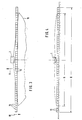
- Fig. 10 shows a further arrangement of the measuring device according to the invention.
- This measuring device 24 consists of four collecting containers 25 arranged one behind the other in the direction of travel and two transversely to the direction of travel l7.
- the collecting containers 25 of the measuring device 24 are adjacent to one another at point P A , that is to say at a distance a which corresponds to half the working width A, at the intersection of the overlap Spreading area or issued at the end of the working width A.
- Fig. Ll shows another arrangement of a measuring device.
- This measuring device 26 has the collecting container 25.
- the measuring device 26 is arranged at the point, ie at a distance a, which corresponds to half the working width A.
- the measuring device 26 again has a narrow and elongated shape, but the elongated measuring device is set up pivoted at an angle of approximately 45 ° to the direction of travel at point P A.
- Fig. L2 shows a further arrangement of the measuring device according to the invention for the measuring method according to the invention.
- the measuring device 27 is initially set up at point P A.
- the point P A is at a distance a from the working width center 2.
- the distance a corresponds to half the working width A.
- the measuring device 28 which is also in the direction of travel elongated and narrow to the direction of travel, arranged.
- the measuring device 29 is set up at a distance x at the point P X.
- the measurement method is carried out in the manner described above, for example according to FIG. 9.
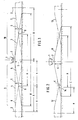
- This measuring device has four individual collecting containers 30. These collecting containers 30 are placed one behind the other in the pendulum frame 3l.
- the pendulum frame 3l has on its two end faces 32 each the joint 33 with which the pendulum frame is connected to the storage frame 34. This makes it possible for the collecting containers 30 to automatically align themselves through their oscillating suspension so that their upper edges are aligned horizontally.
- the locking device 35 is arranged between the storage frame 34 and the pendulum frame 3l. This locking device 35 consists of the strut arranged on the pendulum frame 3l with the clamping bolt 37.
- This clamping bolt 37 protrudes into an elongated hole 38 of the strut 39 arranged on the storage frame 34.
- the clamping nut 40 is placed from the outside, so that the Position of the pendulum frame 3l and thus the collecting container 30 can be locked against the storage frame 34.
- the compensating screws 4l can be arranged at the lower end of the storage frame 34, which can be used to compensate for uneven floors, so that the storage frame 34 stands firmly on the floor.
- extension rods can be attached to the storage frame 34, so that, for example, for late grain fertilization, the collecting containers 30 can be arranged relatively high at a distance from the ground surface, at least up to the height of the grain tip, so as to Late grain fertilization to be able to check the correct setting of the centrifugal spreader.
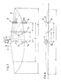
- the volume cup according to FIG. 16 is designed as a standing cylinder 4l.
- This standing cylinder has several scales 42, 43 and 44. Each scale has an identification number.
- the scale 42 is marked with the code number 1
- the scale 43 with the code number 2
- the scale 44 with the code number 3.
- These individual scales represent types of fertilizer with different bulk densities.
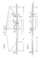
- the two measuring devices 45 and 46 are set up stationary on the field 47 on the floor.
- the centrifugal spreader 1 spreads the fertilizer over the entire spread width B on a spreading path 48.
- the spreading width B corresponds to the spreading range of the fertilizer spreader.
- the overlapping of the scattering paths 48, 49, 50 lying next to one another creates a scattering pattern with the uniform spreading strength S.
- the scattering paths 48 and 49 intersect at the intersection 5l, while the scattering paths 48 and 50 intersect at the intersection 52.
- the working width A corresponds to the distance between the scattering path distances or the distances between the intersection of the individually adjacent scattering paths.
- the measuring device 45 which has a plurality of collection containers set up one behind the other in the direction of travel, is set up. Furthermore, at the intersection 52 or at the end of the working width A, the measuring device 46 consisting of a plurality of collecting containers set up one behind the other in the direction of travel is set up. After the measuring devices 45 and 46 have been set up, the fertilizer is distributed on the field 47 with the centrifugal spreader 1 and when the measuring devices 45 and 46 are "run over", the fertilizers are collected by them at the intended location.
- the graduations 57 have a distance from one another which corresponds to the permissible tolerance deviation from the scattering accuracy. With the help of these graduations, the two fertilizer quantities can be compared with one another and the graduations can be used to determine very easily whether the size of the fertilizer quantities is the same or whether the size of the deviation of the fertilizer quantities from one another is within the permissible range Tolerance range. It should also be mentioned that the measuring chambers 54 and 56, which are separated from one another by a thin partition 58, have the same shape and size.
Landscapes
- Physics & Mathematics (AREA)
- Fluid Mechanics (AREA)
- General Physics & Mathematics (AREA)
- Life Sciences & Earth Sciences (AREA)
- Soil Sciences (AREA)
- Environmental Sciences (AREA)
- Fertilizing (AREA)
- Catching Or Destruction (AREA)
- Dry Formation Of Fiberboard And The Like (AREA)
- Finish Polishing, Edge Sharpening, And Grinding By Specific Grinding Devices (AREA)
- Sowing (AREA)
- Soil Working Implements (AREA)
Priority Applications (1)
| Application Number | Priority Date | Filing Date | Title |
|---|---|---|---|
| EP90100984A EP0376923B1 (fr) | 1986-02-13 | 1987-01-23 | Méthode pour définir le dosage et la largeur d'épandage d'épandeurs centrifuges |
Applications Claiming Priority (4)
| Application Number | Priority Date | Filing Date | Title |
|---|---|---|---|
| DE19863604449 DE3604449A1 (de) | 1986-02-13 | 1986-02-13 | Verfahren zur bestimmung der arbeitsbreite und der streudichte bei schleuderstreuern |
| DE3604449 | 1986-02-13 | ||
| DE19863615817 DE3615817A1 (de) | 1986-02-13 | 1986-05-10 | Messverfahren |
| DE3615817 | 1986-05-10 |
Related Child Applications (2)
| Application Number | Title | Priority Date | Filing Date |
|---|---|---|---|
| EP90100984A Division EP0376923B1 (fr) | 1986-02-13 | 1987-01-23 | Méthode pour définir le dosage et la largeur d'épandage d'épandeurs centrifuges |
| EP90100984.5 Division-Into | 1990-01-18 |
Publications (2)
| Publication Number | Publication Date |
|---|---|
| EP0240655A1 true EP0240655A1 (fr) | 1987-10-14 |
| EP0240655B1 EP0240655B1 (fr) | 1991-05-08 |
Family
ID=25840913
Family Applications (2)
| Application Number | Title | Priority Date | Filing Date |
|---|---|---|---|
| EP87100963A Expired - Lifetime EP0240655B1 (fr) | 1986-02-13 | 1987-01-23 | Procédé pour déterminer l'ampleur de travail et la densité d'épandage d'épandeurs centrifuges |
| EP90100984A Expired - Lifetime EP0376923B1 (fr) | 1986-02-13 | 1987-01-23 | Méthode pour définir le dosage et la largeur d'épandage d'épandeurs centrifuges |
Family Applications After (1)
| Application Number | Title | Priority Date | Filing Date |
|---|---|---|---|
| EP90100984A Expired - Lifetime EP0376923B1 (fr) | 1986-02-13 | 1987-01-23 | Méthode pour définir le dosage et la largeur d'épandage d'épandeurs centrifuges |
Country Status (3)
| Country | Link |
|---|---|
| EP (2) | EP0240655B1 (fr) |
| AT (1) | ATE115358T1 (fr) |
| DE (4) | DE3615817A1 (fr) |
Cited By (2)
| Publication number | Priority date | Publication date | Assignee | Title |
|---|---|---|---|---|
| EP3152994A1 (fr) * | 2015-10-06 | 2017-04-12 | Amazonen-Werke H. Dreyer GmbH & Co. KG | Procédé d'adaptation d'angle de déversement d'un épandeur d'engrais |
| WO2024056245A1 (fr) * | 2022-09-15 | 2024-03-21 | Amazonen-Werke H. Dreyer SE & Co. KG | Dispositif collecteur pour déterminer une distribution d'une substance agricole à épandre |
Families Citing this family (3)
| Publication number | Priority date | Publication date | Assignee | Title |
|---|---|---|---|---|
| DE3821737A1 (de) * | 1988-06-28 | 1990-01-11 | Amazonen Werke Dreyer H | Zentrifugalduengerstreuer |
| DE19749221C2 (de) | 1997-11-07 | 2000-11-30 | Rauch Landmaschfab Gmbh | Vorrichtung zum Bestimmen der physikalischen Eigenschaften von Dünger |
| DE10237539B4 (de) * | 2002-08-16 | 2013-05-29 | Amazonen-Werke H. Dreyer Gmbh & Co. Kg | Schleuderdüngerstreuer |
Citations (4)
| Publication number | Priority date | Publication date | Assignee | Title |
|---|---|---|---|---|
| DE1457844A1 (de) * | 1962-09-20 | 1969-11-13 | Lely Nv C Van Der | Verfahren zum Bestimmen des Streubildes von Vorrichtungen zum Breitstreuen koernigen oder pulvrigen Materials |
| DD211051A1 (de) * | 1982-11-02 | 1984-07-04 | Adl Der Ddr | Verfahren fuer die ermittlung des streufeldes von mineralduengerstreuern |
| DD214988A1 (de) * | 1983-05-03 | 1984-10-31 | Guenter Jaenicke | Messeinrichtung zur ermittlung der verteilgenauigkeit, insbesondere von mineralduengerstreuern |
| US4491023A (en) * | 1980-11-06 | 1985-01-01 | Steffen Graef | Means for checking and/or measuring the actual amount of sprayed plant protective substances |
-
1986
- 1986-05-10 DE DE19863615817 patent/DE3615817A1/de not_active Ceased
-
1987
- 1987-01-23 DE DE3750880T patent/DE3750880D1/de not_active Expired - Fee Related
- 1987-01-23 AT AT90100984T patent/ATE115358T1/de not_active IP Right Cessation
- 1987-01-23 EP EP87100963A patent/EP0240655B1/fr not_active Expired - Lifetime
- 1987-01-23 DE DE8787100963T patent/DE3769824D1/de not_active Expired - Lifetime
- 1987-01-23 EP EP90100984A patent/EP0376923B1/fr not_active Expired - Lifetime
- 1987-02-10 DE DE8701948U patent/DE8701948U1/de not_active Expired
Patent Citations (4)
| Publication number | Priority date | Publication date | Assignee | Title |
|---|---|---|---|---|
| DE1457844A1 (de) * | 1962-09-20 | 1969-11-13 | Lely Nv C Van Der | Verfahren zum Bestimmen des Streubildes von Vorrichtungen zum Breitstreuen koernigen oder pulvrigen Materials |
| US4491023A (en) * | 1980-11-06 | 1985-01-01 | Steffen Graef | Means for checking and/or measuring the actual amount of sprayed plant protective substances |
| DD211051A1 (de) * | 1982-11-02 | 1984-07-04 | Adl Der Ddr | Verfahren fuer die ermittlung des streufeldes von mineralduengerstreuern |
| DD214988A1 (de) * | 1983-05-03 | 1984-10-31 | Guenter Jaenicke | Messeinrichtung zur ermittlung der verteilgenauigkeit, insbesondere von mineralduengerstreuern |
Cited By (2)
| Publication number | Priority date | Publication date | Assignee | Title |
|---|---|---|---|---|
| EP3152994A1 (fr) * | 2015-10-06 | 2017-04-12 | Amazonen-Werke H. Dreyer GmbH & Co. KG | Procédé d'adaptation d'angle de déversement d'un épandeur d'engrais |
| WO2024056245A1 (fr) * | 2022-09-15 | 2024-03-21 | Amazonen-Werke H. Dreyer SE & Co. KG | Dispositif collecteur pour déterminer une distribution d'une substance agricole à épandre |
Also Published As
| Publication number | Publication date |
|---|---|
| EP0376923B1 (fr) | 1994-12-14 |
| EP0376923A2 (fr) | 1990-07-04 |
| EP0376923A3 (fr) | 1991-10-02 |
| EP0240655B1 (fr) | 1991-05-08 |
| DE3615817A1 (de) | 1987-11-12 |
| ATE115358T1 (de) | 1994-12-15 |
| DE8701948U1 (de) | 1987-07-23 |
| DE3750880D1 (de) | 1995-01-26 |
| DE3769824D1 (de) | 1991-06-13 |
Similar Documents
| Publication | Publication Date | Title |
|---|---|---|
| DE3310424C2 (de) | Vorrichtung zum Ausbringen von Schüttgut, wie Dünger, Saatgut od.dgl. | |
| EP0751703B1 (fr) | Procede permettant de determiner des donnees de reglage pour un epandeur d'engrais centrifuge | |
| DE4105045A1 (de) | Verfahren zum einstellen der dosierorgane einer verteilmaschine | |
| EP2883436B1 (fr) | Procédé de détermination de données de réglage pour un épandeur centrifuge | |
| EP0567495B2 (fr) | Procede et dispositif pour determiner, pour un type particulier d'engrais, les valeurs de reglage d'un epandeur d'engrais necessaires pour obtenir la largeur et la quantite d'epandage voulues | |
| DE3050904C2 (fr) | ||
| DE69725773T2 (de) | Streuer mit Gewichtsmessung | |
| EP0240655B1 (fr) | Procédé pour déterminer l'ampleur de travail et la densité d'épandage d'épandeurs centrifuges | |
| DE19500824A1 (de) | Verfahren zur Ermittlung von Einstelldaten für einen Schleuderdüngerstreuer | |
| DE102021106941A1 (de) | Verfahren zum Ermitteln der Lage eines Portionsschwerpunkts einer Granulatportion | |
| EP3017681A1 (fr) | Épandeur centrifugue | |
| DE102004004133A1 (de) | Verfahren und Vorrichtung zum optischen Zählen kleiner Körperchen | |
| DE4102783A1 (de) | Schleuderduengerstreuer | |
| DE3604449A1 (de) | Verfahren zur bestimmung der arbeitsbreite und der streudichte bei schleuderstreuern | |
| DE10237539B4 (de) | Schleuderdüngerstreuer | |
| DE2555011B2 (de) | Maschine zum Ausbringen von korn- und pulverförmigeni Gut | |
| DE102005012886A1 (de) | Streufahrzeug für den Winterdienst | |
| DE69123758T2 (de) | Vorrichtung zur Ausstreuung eines körnigen Materials | |
| EP3981239B1 (fr) | Procédé de planification et/ou de mise en oeuvre d'un processus d'apport d'engrais | |
| DE3325542A1 (de) | Verfahren zur bestimmung und regelung der ausbringmenge bei einer verteilmaschine | |
| DE3821738A1 (de) | Pneumatikduengerstreuer | |
| EP0119292B1 (fr) | Procédé de réglage de l'apport de produits agricoles sur une surface | |
| DE3217010C2 (de) | Fahrbarer Kultiviergutverteiler | |
| DE8817220U1 (de) | Landwirtschaftliche Maschine zum Verteilen von Gut | |
| DE3914126C1 (en) | Spreading fertiliser on field - involves plates designed so that one spreader platte gives even distribution over two rows of plants |
Legal Events
| Date | Code | Title | Description |
|---|---|---|---|
| PUAI | Public reference made under article 153(3) epc to a published international application that has entered the european phase |
Free format text: ORIGINAL CODE: 0009012 |
|
| AK | Designated contracting states |
Kind code of ref document: A1 Designated state(s): AT BE CH DE ES FR GB IT LI LU NL SE |
|
| 17P | Request for examination filed |
Effective date: 19871119 |
|
| 17Q | First examination report despatched |
Effective date: 19890904 |
|
| GRAA | (expected) grant |
Free format text: ORIGINAL CODE: 0009210 |
|
| AK | Designated contracting states |
Kind code of ref document: B1 Designated state(s): DE |
|
| XX | Miscellaneous (additional remarks) |
Free format text: TEILANMELDUNG 90100984.5 EINGEREICHT AM 23/01/87. |
|
| REF | Corresponds to: |
Ref document number: 3769824 Country of ref document: DE Date of ref document: 19910613 |
|
| EN | Fr: translation not filed | ||
| PLBE | No opposition filed within time limit |
Free format text: ORIGINAL CODE: 0009261 |
|
| STAA | Information on the status of an ep patent application or granted ep patent |
Free format text: STATUS: NO OPPOSITION FILED WITHIN TIME LIMIT |
|
| 26N | No opposition filed | ||
| PGFP | Annual fee paid to national office [announced via postgrant information from national office to epo] |
Ref country code: DE Payment date: 19930115 Year of fee payment: 7 |
|
| PG25 | Lapsed in a contracting state [announced via postgrant information from national office to epo] |
Ref country code: DE Effective date: 19941001 |