EP0240139A2 - Bobine de déviation autoconvergente pour un tube d'image en couleur en ligne - Google Patents
Bobine de déviation autoconvergente pour un tube d'image en couleur en ligne Download PDFInfo
- Publication number
- EP0240139A2 EP0240139A2 EP87301644A EP87301644A EP0240139A2 EP 0240139 A2 EP0240139 A2 EP 0240139A2 EP 87301644 A EP87301644 A EP 87301644A EP 87301644 A EP87301644 A EP 87301644A EP 0240139 A2 EP0240139 A2 EP 0240139A2
- Authority
- EP
- European Patent Office
- Prior art keywords
- deflection
- convergence
- windings
- adjustable
- series
- Prior art date
- Legal status (The legal status is an assumption and is not a legal conclusion. Google has not performed a legal analysis and makes no representation as to the accuracy of the status listed.)
- Granted
Links
- 238000004804 winding Methods 0.000 claims abstract description 60
- 238000012937 correction Methods 0.000 claims abstract description 30
- 238000010894 electron beam technology Methods 0.000 claims description 20
- 230000008878 coupling Effects 0.000 claims description 5
- 238000010168 coupling process Methods 0.000 claims description 5
- 238000005859 coupling reaction Methods 0.000 claims description 5
- 230000000694 effects Effects 0.000 claims description 4
- 230000003247 decreasing effect Effects 0.000 claims 1
- 230000004907 flux Effects 0.000 abstract description 8
- 230000001419 dependent effect Effects 0.000 description 7
- OAICVXFJPJFONN-UHFFFAOYSA-N Phosphorus Chemical compound [P] OAICVXFJPJFONN-UHFFFAOYSA-N 0.000 description 5
- 238000004519 manufacturing process Methods 0.000 description 4
- 238000013461 design Methods 0.000 description 3
- 238000006073 displacement reaction Methods 0.000 description 2
- 239000011159 matrix material Substances 0.000 description 2
- 238000000034 method Methods 0.000 description 2
- 230000009467 reduction Effects 0.000 description 2
- 230000035945 sensitivity Effects 0.000 description 2
- 241000226585 Antennaria plantaginifolia Species 0.000 description 1
- 238000013459 approach Methods 0.000 description 1
- 238000005452 bending Methods 0.000 description 1
- 230000009286 beneficial effect Effects 0.000 description 1
- 238000009125 cardiac resynchronization therapy Methods 0.000 description 1
- 230000008859 change Effects 0.000 description 1
- 238000007796 conventional method Methods 0.000 description 1
- 238000010586 diagram Methods 0.000 description 1
- 238000009826 distribution Methods 0.000 description 1
- 239000011521 glass Substances 0.000 description 1
- 230000006872 improvement Effects 0.000 description 1
- 239000002991 molded plastic Substances 0.000 description 1
- 230000003252 repetitive effect Effects 0.000 description 1
- 238000007493 shaping process Methods 0.000 description 1
Images


Classifications
-
- H—ELECTRICITY
- H04—ELECTRIC COMMUNICATION TECHNIQUE
- H04N—PICTORIAL COMMUNICATION, e.g. TELEVISION
- H04N9/00—Details of colour television systems
- H04N9/12—Picture reproducers
- H04N9/16—Picture reproducers using cathode ray tubes
- H04N9/28—Arrangements for convergence or focusing
Definitions
- the present invention relates generally to the correction of convergence errors created in a cathode ray tube (CRT) employing magnetic deflection of the electron beam, and more particularly to the correction of positional and misconvergence errors in an in-line gun assembly with a self-converging deflection yoke structure.
- the invention is particularly adapted to systems which must display information in raster format and/or stroke written format, the latter particularly being degraded if convergence control such as provided by the present invention is not employed.
- three separate beams are generated by discrete electron guns and focused on a shadow mask disposed on the interior surface of the CRT viewing screen.
- the beam triad passes through a plurality of pin holes in the mask and then diverges to energise adjacent dot triads of red, green and blue phosphos to provide corresponding colour emissions from the face of the CRT.
- Convergence is said to occur when each of the three electron beams lands on its respective coloured phosphor dot of a given phosphor triad for each triad over the entire face of the viewing screen.
- the three guns are arranged in a triangular configuration and inclined to converge at a central point in the viewing screen.
- a magnetic deflection yoke is configured to provide a uniform deflection field. Misconvergence is accordingly corrected with extra circuitry, such as disclosed in US-A-4,385,259, which applies a convergence correction to the deflection yoke dependent on the beam position.
- the most critical aspect of deflection yoke design for the delta configuration is a disposal of the windings to establish a uniform magnetic field throughout the region occupied by the scanning beam.
- the deflection yoke generally consists of two pairs of coils wound at right angles to each other and oriented along the beam axis.
- Two opposing coils are series connected so that their magnetic fields add.
- the magnetic lines of flux are oriented horizontally to cause vertical deflection, since the resulting deflection of the electron beam is at right angles to the magnetic lines of flux.
- a horizontal deflection is produced by the opposing pair of coils whose magnetic lines of flux pass vertically through the neck of the tube.
- a simpler approach is that of arranging the electron guns in a linear array to provide substantially converging electron beams at the centre of the viewing screen and shaping the deflection coil to provide inherent convergence control by providing a non-uniform deflection field.
- This technique requires critical alignment of the deflection yoke on the neck of the CRT, along with permanent magnets which may be statically trimmed for optimum convergence correction at the centre of the face of the CRT.
- the misconvergence in one plane can be reduced substantially to zero by deliberately introducing an astigmatic deflection of the magnetic fields into the deflection yoke design.
- the horizontal field is arranged to provide a barrel shaped deflection and the vertical field to provide a pin cushion deflection.
- the yoke must be wound with a high degree of precision.
- each turn of wire is precisely placed into the winding grooves of molded plastic rings that are cemented to each end of a toroidal core.
- Optimum convergence is then achieved by positioning the yoke in relation to the picture tube neck so as properly to align the three beams with the centre of deflection of the yoke.
- a further improvement in the art utilises a deflection yoke coupled to a convergence coil which is adjustable to minimise misconvergence.
- a deflection yoke coupled to a convergence coil which is adjustable to minimise misconvergence.
- the present invention overcomes the shortcomings of the prior art by an improved CRT convergence circuit design which yields substantial production interchangeability without the need for dynamically modifying the deflection amplifier waveforms, by providing individual adjustment of the convergence network inductance and resistance to match the L/R time constants.
- the present invention provides deflection positional and convergence correction to a cathode ray tube convergence system of the type including a magnetically deflected colour cathode ray tube with a viewing screen for displaying a pattern written thereon by a plurality of electron beam sources.
- the electron beam sources are arranged in a plane and disposed to converge the electron beams at the centre of the viewing screen.
- the system includes a deflection yoke with horizontal and vertical deflection windings to deflect the electron beams in accordance with a commanded deflection signal.
- the yoke also acts to converge the electron beams on a focal plane coincident with the viewing screen.
- convergence means Coupled to the deflection yoke and responsive to at least a portion of the command deflection signal is convergence means comprised of convergence coil windings. At least one impedance parameter of the windings of the convergence coil is independently adjustable and selected to provide a predetermined impedance ratio with respect to predetemined impedance parameters of the deflection windings.
- the applied deflection signals are thereby apportioned between the deflection and convergence coils to provide a beam deflecting flux proportional to the commanded deflection signal and a beam deflection centre that is independent of the pattern written on the screen.
- the resulting currents in the deflection windings and convergence windings are linearly proportional to the commanded deflection signal wavforms.
- a pluality of convergence windings have a mutually coupled variable self-inductance and are provided with independently adjustable series resistances, whereby the time constants of the associated deflection and convergence coils are made equal.
- Circuits for both series connected and parallel connected deflection coils are provided.
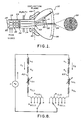
- FIG. l a schematic cross section of a typical colour CRT of the shadow mask type is illustrated. It comprises a glass envelope l0 including a viewing surfae l2 with a cylindrical neck l4. Conventionally mounted within the envelope l0 are three colour CRT electron guns l6, l8 and 20. Electrodes 22, 24 and 26 focus the electron beams 28, 30 and 32 nominally at the centre 34 of the viewing face l2. At the viewing surface of the envelope l0 is a shadow mask 36 which comprises a metallic plate with a matrix of small holes. The internal surface of the faceplate of the CRT is provided with a corresponding matrix of red, green and blue phosphor dots, G,R,B as illustrated at 38. A conventional deflection yoke 40 is affixed to the envelope l0.
- the beams 28, 30, 32 are deflected in accordance with horizontal and vertical deflection control signals by means of the magnetic fields produced by the coils in the deflection yoke 40 and have an effective deflection plane 44.
- These signals may provide raster displays or stroke written displays or a combination of both by conventional techniques.
- the three electron guns l6, l8, 20 may conventionally be arranged in a linear array to illuminate the viewing screen on a horizontal or vertical line, as shown at 38 by shaded areas G, R, B. Since the electron beams are disposed along a finite width, the outer beams 28 and 32 enter the magnetic field of the deflection yoke at different angles and may be aligned to converge on the phosphor screen at its centre 34. However, when the three beams are deflected at an angle ⁇ , they do not converge on their reflective coloured phosphor dots at the new triad position, resulting in colour fringing.
- the deflection flux density and therefore the position of the electron beams is proportional to the sum of the currents in the deflection windings.
- the centre of deflection of the yoke which is the apparent geometric point 43 through the deflection plane 44 at which the electron beams are angularly displaced, is proportional to the ratio of the currents in the deflection windings, and may be varied in small amount to introduce a convergence correction, since the flux density across the in-line beams is not uniform, and therefore the bending influence on an individual beam will be dependent on its displacement from the yoke centre.
- Such a convergence correction may be introduced by electrically connecting each deflection winding to a corresponding convergence inductor with a series resistor for the axis along which the error correction is required, as in Figure 2.
- the inductors L CU and L CL are mutually coupled, as are series resistances R CUS and R CLS .
- a predetermined current may be diverted from the deflection winding coupled thereto.
- the deflection sensitivity will not be materially reduced, and the current ratios of the deflection coils may be adjusted for optimal convergence over the viewing face of the cathode ray tube.
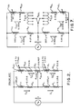
- a first branch comprises an upper deflection yoke coil L U series connected with a lower deflection yoke coil L L .
- Each coil typically has an inductance value of l60 ⁇ h.
- Inherent in the coil structure is a series resistance, which is typically of the order of 0.l5 ohms per coil.
- a second branch comprised of an upper convergence coil L CU and a lower convergence coil L CL , has an adjustable potentiometer R P interposed between the convergence coils, with the adjustable tap of the potentiometer coupled to the common point of the series-connected deflection coils L U and L L .
- the Convergence coils L CU and L CL have associated series resistances R CU and R CL , respectively, of 3.2 ohms nominal.
- the convergence coils are coupled on a common core so as to provide an inductance adjustable in the range of l.5 to 2.8 mh.
- the coils preferably are mutually coupled so that an increase in the inductance of the first coil results in a decrease in inductance of the second coil, and vice versa.
- the variable inductances and potentiometer permit adjustment of the convergence of the electron beam for production yokes and production CRTs to correct for small tolerances and variances in electron beam direction; however, it has been found that optimum convergence for stroke displays cannot be
- Figure 3 shows the face of a CRT on which a stroke written pattern for use in a navigational display is provided. Stroke written circle 50, index 52, and markers 54, 56, 58 and 60 are displayed on a two-colour raster background 62, 64. It is desired that the apex of the markers 54-60 should fall on the circle 50. However, it is seen that markers 54 and 58 are displaced from their desired positions.
- Figure 4 shows an example of a stroke pattern dependent convergence error that has been observed.
- a beam at an initial position 70 was blanked and deflected to position 72, a short distance therefrom.
- the resultant display at 72 was found to be properly converged.
- position 76 when the beam was deflected a relatively large distance from an initial position 74 to say, position 76, the red, green and blue beams were found to be misconverged, resulting in a visible fringe about the desired colour image.
- the present invention corrects the above-described undesirable results by independently matching the RL time constants of the yoke windings with the corresponding time constants of the cooperative convergence coil windings, so that the beam deflecting flux density will be proportional to the commanded deflection current and the beam deflection centre will be a constant, independent of frequency and deflection current signal waveforms, and results in proportioning the current signals in the deflection coils so that they are representative of the deflection current signal waveforms.
- Figure 5 shows current waveforms applied to a prior art self-converging deflection yoke and convergence network of the type illustrated in Figure 2.
- Waveform 84 is a sawtooth representative of an applied deflection current.
- Waveform 82 shows the resultant current through the convergence network with waveform distortion readily apparent as a result of the divergence of current to the convergence coil.
- the waveform 84 is again the applied input current, while waveform 86 shows the corresponding convergence coil current. Note that the waveform 86 is linearly proportional to the waveform 84 and may be readily scaled by a suitable gain factor to provide the desired peak deflection.
- Figures 5 and 6 illustrate the effectiveness of the present invention in correcting errors in misconvergence and beam centre displacement.
- the time constant ratio L U /R U of the upper deflection coil must be matched to the time constant ratio L CU /(R CU +R CUS ) of the upper convergence coil, and the time constant L L /R L of the lower deflection coil must be matched to the time constant L CL /(R CL + R CLS ) of the lower convergence coil.
- the inductors L CU and L CL are mutually dependent, as are the series resistances R CUS and R CLS , which are determined by the position of the wiper arm on the potentiometer R P .
- the prior art is incapable of matching the time constants over a relatively wide range of ⁇ 4% since this requires the capability of independently adjusting at least the series resistors R CUS and R CLS or the inductors L CL and L CU .
- the current ratio range that can be achieved with both convergence networks connected and the inductors set to provide the maximum ratio range. This is preferably obtained by mutually coupling the convergence coils so that one inductor is at a maximum value while the other is at a minimum value. From equation (3) and choosing an inductance value of 3.0 mh for the upper convergence coil, the series resistance R CU + R CUS is seen to have a value of Since the selected inductor has a typical winding resistance of 2.5 ohm, an additional series resistance R CUS of 0.3l25 ohm is required. This is provided by adjusting the wiper of switch R SEL to provide an appropriate resistance at resistor network R CUS . This results in a branch current of 2.848 amps in L U .
- the upper loop convergence network time constant be matched to the predetermined time constant value of the upper yoke half and the lower loop convergence network time constant matched to the time constant of the lower yoke half.
- the time constants of the two yoke halves need not be equal.
- the time constants are matched in the upper current loops and are also matched in the lower current loops. Note that the time constants of the deflection coils and convergence coils could still be matched, but to different values in the upper and lower sections, if the upper yoke inductance L U has a different value than the lower yoke inductance L L .
- Equation (l) and equation (2) are satisfied, and the desired deflection signal waveform of Figure 6 is obtained, overcoming the positional error and misconvergence error of the prior art that otherwise occurs with random signal waveforms.
- Changes in the value of K1 and K2 are readily accommodated by adjusting the gain of a conventional deflection amplifier.
- the non-uniform field of the conventional in-line gun yoke has been shifted upward and thus when used with the in-line gun CRT the bottom electron beam (red) will be deflected upward more than the other two beams from the nominal commanded position. This effects the desired convergence correction.
- the adjustment range can be increased to ⁇ 5% by leaving the upper or lower section of R SEL open, thereby disconnecting one convergence coil.
- a 5% current reduction ratio between the upper and lower deflection coils has been obtained using the minimum inductance of 3 mh.
- the convergence correction can be precisely trimmed to five percent, or any desired lesser value, by slight adjustments in the series resistors and a corresponding change in the inductors to match the L/R time constants.
- the deflection coils comprise a first circuit branch 60, a first deflection yoke half winding L U with an internal resistance R U , series-connected with a convergence winding L CU and an internal resistance R CU , and an adjustable series resistance R CUS .
- a second branch circuit 62 includes a second deflection yoke half winding L L with a series resistance R L in series connection with a second convergence winding L CL , with its series resistance R CL and an adjustable series resistance R CLS .
- the values of parameters L U , R U , L L , and R L are predetermined in accordance with the normal deflection sensitivity.
- the time constant of the left-hand branch is matched to the time constant of the right-hand branch, Appropriate resistance for the left-hand series element R CUS is provided by the wiper of a selector switch R SELU .
- R CUS may also be a potentiometer.
- the series resistor R CLS is adjusted by the wiper of the selector switch R SELL .
- the windings L CU and L CL of the convergence coil may be coupled by mutual inductance, although they may also be independently selected with appropriate circuit components, in which case predetermined series resistors may be used.
- the parallel branches through which currents I1 and I2 flow are connected to receive the deflection current signal I which is the commanded deflection current.
Landscapes
- Engineering & Computer Science (AREA)
- Multimedia (AREA)
- Signal Processing (AREA)
- Video Image Reproduction Devices For Color Tv Systems (AREA)
Applications Claiming Priority (2)
| Application Number | Priority Date | Filing Date | Title |
|---|---|---|---|
| US06/846,406 US4677349A (en) | 1986-03-31 | 1986-03-31 | Self converging deflection yoke for in-line gun color CRT |
| US846406 | 1986-03-31 |
Publications (3)
| Publication Number | Publication Date |
|---|---|
| EP0240139A2 true EP0240139A2 (fr) | 1987-10-07 |
| EP0240139A3 EP0240139A3 (en) | 1989-02-08 |
| EP0240139B1 EP0240139B1 (fr) | 1992-12-16 |
Family
ID=25297843
Family Applications (1)
| Application Number | Title | Priority Date | Filing Date |
|---|---|---|---|
| EP87301644A Expired EP0240139B1 (fr) | 1986-03-31 | 1987-02-25 | Bobine de déviation autoconvergente pour un tube d'image en couleur en ligne |
Country Status (4)
| Country | Link |
|---|---|
| US (1) | US4677349A (fr) |
| EP (1) | EP0240139B1 (fr) |
| JP (1) | JPS62242483A (fr) |
| DE (1) | DE3783063T2 (fr) |
Families Citing this family (5)
| Publication number | Priority date | Publication date | Assignee | Title |
|---|---|---|---|---|
| JPH0339969U (fr) * | 1989-08-30 | 1991-04-17 | ||
| JPH0348842U (fr) * | 1989-09-19 | 1991-05-10 | ||
| KR100284483B1 (ko) * | 1997-12-17 | 2001-03-15 | 이형도 | 편향 요크의 미스컨버전스 및 기하학적 왜곡 보정 장칙 |
| TW428200B (en) * | 1998-12-01 | 2001-04-01 | Koninkl Philips Electronics Nv | Colour display device with a deflection-dependent distance between outer beams |
| US20080116390A1 (en) * | 2006-11-17 | 2008-05-22 | Pyramid Technical Consultants, Inc. | Delivery of a Charged Particle Beam |
Family Cites Families (6)
| Publication number | Priority date | Publication date | Assignee | Title |
|---|---|---|---|---|
| US3613109A (en) * | 1969-08-15 | 1971-10-12 | Admiral Corp | Horizontal convergence circuit |
| GB1378521A (en) * | 1971-01-06 | 1974-12-27 | Rca Corp | Passive vertical convergence circuit |
| US3784869A (en) * | 1971-03-29 | 1974-01-08 | Victor Co Ltd | Vertical convergence circuit |
| NL155430B (nl) * | 1972-12-15 | 1977-12-15 | Philips Nv | Kleurenbeeldweergeefinrichting voorzien van een beeldweergeefbuis. |
| JPS58212039A (ja) * | 1982-06-01 | 1983-12-09 | Denki Onkyo Co Ltd | 偏向ヨ−ク装置 |
| JPS6120480A (ja) * | 1984-07-06 | 1986-01-29 | Denki Onkyo Co Ltd | 偏向ヨ−ク装置 |
-
1986
- 1986-03-31 US US06/846,406 patent/US4677349A/en not_active Expired - Lifetime
- 1986-12-09 JP JP61293318A patent/JPS62242483A/ja active Pending
-
1987
- 1987-02-25 DE DE8787301644T patent/DE3783063T2/de not_active Expired - Fee Related
- 1987-02-25 EP EP87301644A patent/EP0240139B1/fr not_active Expired
Also Published As
| Publication number | Publication date |
|---|---|
| US4677349A (en) | 1987-06-30 |
| DE3783063D1 (de) | 1993-01-28 |
| DE3783063T2 (de) | 1993-05-06 |
| EP0240139A3 (en) | 1989-02-08 |
| EP0240139B1 (fr) | 1992-12-16 |
| JPS62242483A (ja) | 1987-10-23 |
Similar Documents
| Publication | Publication Date | Title |
|---|---|---|
| US4257024A (en) | Color picture tube apparatus | |
| EP0540113B1 (fr) | Unité de déviation de tube image munie de bobines de déviation d'image du type à semi-selle | |
| US4689525A (en) | Color cathode ray tube device | |
| US4788470A (en) | Deflection yoke apparatus with compensation magnetic field generating means | |
| US6215257B1 (en) | Apparatus for correcting misconvergence and geometric distortion of deflection yoke | |
| US4500816A (en) | Convergence control apparatus for color cathode ray tube display systems | |
| JPH0433197B2 (fr) | ||
| EP0240139B1 (fr) | Bobine de déviation autoconvergente pour un tube d'image en couleur en ligne | |
| US5668447A (en) | Deflection yoke and cathode-ray tube apparatus comprising the same | |
| US4881015A (en) | Color cathode-ray apparatus having an improved deflection unit | |
| KR0139475B1 (ko) | 컬러 음극선관용 전자 편향 요크 | |
| EP0588666B1 (fr) | Bobine de déflexion | |
| KR20010086319A (ko) | 컬러 음극선관용 편향요크 및 미스컨버전스 보정방법 | |
| EP1089312B1 (fr) | Tube à rayon cathodique couleur avec appareil de correction de convergence | |
| US3441788A (en) | Circuit arrangements for dynamic lateral convergence | |
| US4388602A (en) | Electron beam influencing apparatus incorporating vertical beam movement function | |
| KR100347178B1 (ko) | 화면 불균형 개선 회로 | |
| US6252359B1 (en) | Deflection apparatus | |
| US3588566A (en) | Electromagnetic deflection yoke having bypassed winding turns | |
| JPS60253136A (ja) | 偏向ヨ−ク装置 | |
| US6476569B2 (en) | Deflection apparatus, cathode ray tube apparatus and beam landing adjustment method | |
| JPH033034Y2 (fr) | ||
| KR810001808B1 (ko) | 칼러텔레비젼 수신기용 편향 요크장치 | |
| KR100443743B1 (ko) | 편향요크의 미스컨버전스 보정장치의 개선 회로 | |
| JPH11176358A (ja) | インライン型カラー受像管用偏向ヨーク |
Legal Events
| Date | Code | Title | Description |
|---|---|---|---|
| PUAI | Public reference made under article 153(3) epc to a published international application that has entered the european phase |
Free format text: ORIGINAL CODE: 0009012 |
|
| AK | Designated contracting states |
Kind code of ref document: A2 Designated state(s): DE FR GB IT |
|
| PUAL | Search report despatched |
Free format text: ORIGINAL CODE: 0009013 |
|
| AK | Designated contracting states |
Kind code of ref document: A3 Designated state(s): DE FR GB IT |
|
| 17P | Request for examination filed |
Effective date: 19890721 |
|
| ITTA | It: last paid annual fee | ||
| 17Q | First examination report despatched |
Effective date: 19920310 |
|
| ITF | It: translation for a ep patent filed | ||
| GRAA | (expected) grant |
Free format text: ORIGINAL CODE: 0009210 |
|
| AK | Designated contracting states |
Kind code of ref document: B1 Designated state(s): DE FR GB IT |
|
| ET | Fr: translation filed | ||
| REF | Corresponds to: |
Ref document number: 3783063 Country of ref document: DE Date of ref document: 19930128 |
|
| PLBE | No opposition filed within time limit |
Free format text: ORIGINAL CODE: 0009261 |
|
| STAA | Information on the status of an ep patent application or granted ep patent |
Free format text: STATUS: NO OPPOSITION FILED WITHIN TIME LIMIT |
|
| 26N | No opposition filed | ||
| PGFP | Annual fee paid to national office [announced via postgrant information from national office to epo] |
Ref country code: FR Payment date: 19941213 Year of fee payment: 9 |
|
| PGFP | Annual fee paid to national office [announced via postgrant information from national office to epo] |
Ref country code: GB Payment date: 19941219 Year of fee payment: 9 |
|
| PGFP | Annual fee paid to national office [announced via postgrant information from national office to epo] |
Ref country code: DE Payment date: 19941220 Year of fee payment: 9 |
|
| PG25 | Lapsed in a contracting state [announced via postgrant information from national office to epo] |
Ref country code: GB Effective date: 19960225 |
|
| GBPC | Gb: european patent ceased through non-payment of renewal fee |
Effective date: 19960225 |
|
| PG25 | Lapsed in a contracting state [announced via postgrant information from national office to epo] |
Ref country code: FR Effective date: 19961031 |
|
| PG25 | Lapsed in a contracting state [announced via postgrant information from national office to epo] |
Ref country code: DE Effective date: 19961101 |
|
| REG | Reference to a national code |
Ref country code: FR Ref legal event code: ST |
|
| PG25 | Lapsed in a contracting state [announced via postgrant information from national office to epo] |
Ref country code: IT Free format text: LAPSE BECAUSE OF NON-PAYMENT OF DUE FEES;WARNING: LAPSES OF ITALIAN PATENTS WITH EFFECTIVE DATE BEFORE 2007 MAY HAVE OCCURRED AT ANY TIME BEFORE 2007. THE CORRECT EFFECTIVE DATE MAY BE DIFFERENT FROM THE ONE RECORDED. Effective date: 20050225 |