EP0240028B1 - Vorrichtung zur federnden Abstützung von Maschinen auf dem Boden - Google Patents
Vorrichtung zur federnden Abstützung von Maschinen auf dem Boden Download PDFInfo
- Publication number
- EP0240028B1 EP0240028B1 EP87104931A EP87104931A EP0240028B1 EP 0240028 B1 EP0240028 B1 EP 0240028B1 EP 87104931 A EP87104931 A EP 87104931A EP 87104931 A EP87104931 A EP 87104931A EP 0240028 B1 EP0240028 B1 EP 0240028B1
- Authority
- EP
- European Patent Office
- Prior art keywords
- rubber component
- side wall
- load
- feet
- end wall
- Prior art date
- Legal status (The legal status is an assumption and is not a legal conclusion. Google has not performed a legal analysis and makes no representation as to the accuracy of the status listed.)
- Expired - Lifetime
Links
- 238000013016 damping Methods 0.000 claims abstract description 6
- 239000007788 liquid Substances 0.000 claims description 18
- 239000002184 metal Substances 0.000 claims description 15
- 238000004073 vulcanization Methods 0.000 claims description 9
- 230000000694 effects Effects 0.000 abstract description 2
- 239000012530 fluid Substances 0.000 abstract 1
- 230000006378 damage Effects 0.000 description 3
- 230000007704 transition Effects 0.000 description 3
- 230000035939 shock Effects 0.000 description 2
- 239000000725 suspension Substances 0.000 description 2
- 229910001369 Brass Inorganic materials 0.000 description 1
- 239000006096 absorbing agent Substances 0.000 description 1
- 239000012790 adhesive layer Substances 0.000 description 1
- 239000010951 brass Substances 0.000 description 1
- 230000006835 compression Effects 0.000 description 1
- 238000007906 compression Methods 0.000 description 1
- 238000010276 construction Methods 0.000 description 1
- 238000005336 cracking Methods 0.000 description 1
- 238000011161 development Methods 0.000 description 1
- 230000018109 developmental process Effects 0.000 description 1
- 238000006073 displacement reaction Methods 0.000 description 1
- 230000005489 elastic deformation Effects 0.000 description 1
- 239000010410 layer Substances 0.000 description 1
- 230000000284 resting effect Effects 0.000 description 1
- 238000007665 sagging Methods 0.000 description 1
Images
Classifications
-
- F—MECHANICAL ENGINEERING; LIGHTING; HEATING; WEAPONS; BLASTING
- F16—ENGINEERING ELEMENTS AND UNITS; GENERAL MEASURES FOR PRODUCING AND MAINTAINING EFFECTIVE FUNCTIONING OF MACHINES OR INSTALLATIONS; THERMAL INSULATION IN GENERAL
- F16F—SPRINGS; SHOCK-ABSORBERS; MEANS FOR DAMPING VIBRATION
- F16F13/00—Units comprising springs of the non-fluid type as well as vibration-dampers, shock-absorbers, or fluid springs
- F16F13/002—Units comprising springs of the non-fluid type as well as vibration-dampers, shock-absorbers, or fluid springs comprising at least one fluid spring
-
- F—MECHANICAL ENGINEERING; LIGHTING; HEATING; WEAPONS; BLASTING
- F16—ENGINEERING ELEMENTS AND UNITS; GENERAL MEASURES FOR PRODUCING AND MAINTAINING EFFECTIVE FUNCTIONING OF MACHINES OR INSTALLATIONS; THERMAL INSULATION IN GENERAL
- F16F—SPRINGS; SHOCK-ABSORBERS; MEANS FOR DAMPING VIBRATION
- F16F13/00—Units comprising springs of the non-fluid type as well as vibration-dampers, shock-absorbers, or fluid springs
- F16F13/04—Units comprising springs of the non-fluid type as well as vibration-dampers, shock-absorbers, or fluid springs comprising both a plastics spring and a damper, e.g. a friction damper
- F16F13/06—Units comprising springs of the non-fluid type as well as vibration-dampers, shock-absorbers, or fluid springs comprising both a plastics spring and a damper, e.g. a friction damper the damper being a fluid damper, e.g. the plastics spring not forming a part of the wall of the fluid chamber of the damper
- F16F13/08—Units comprising springs of the non-fluid type as well as vibration-dampers, shock-absorbers, or fluid springs comprising both a plastics spring and a damper, e.g. a friction damper the damper being a fluid damper, e.g. the plastics spring not forming a part of the wall of the fluid chamber of the damper the plastics spring forming at least a part of the wall of the fluid chamber of the damper
Definitions
- the invention relates to a device for the resilient support of machines on the floor according to the preamble of claim 1.
- Such a device is known from DE-C 2 353 868.
- the central portion of the end wall is designed as a cylindrical projection, on the upper end of which the load carrier plate is arranged and the lower end of which is connected to the upper end of the hollow cylindrical side wall by the annular section of the end wall, which is designed as a flat annular disk.
- several rigid stiffening rings are arranged at an axial distance from one another, which coaxially surround the hollow cylindrical side wall of the rubber component.
- the hollow cylindrical side wall of the rubber component is firmly connected to the surface of the base plate by an adhesive layer.
- the load carrier plate or a base plate braced with it extends in the radial direction over the outer circumference of the hollow cylindrical side wall of the rubber component, as a result of which the load carrier plate or the base plate can be supported on the upper end of the hollow cylindrical side wall if the front wall is correspondingly deep in due to an increased load the pressure chamber filled with air is pressed in.
- the known device has the disadvantage that, because of the radial extension of the annular section, the end wall of the rubber component is only able to oppose a slight deformation resistance against axial loading and in the right-angled transition of the annular section into the central cylindrical projection on the one hand and into the upper end of the hollow cylindrical side wall on the other hand When there is an axial load, stress peaks occur which, with the appropriate size, can lead to cracks in the rubber component.
- the known device has the disadvantage that, in the event of an axial overload, the device can collapse by buckling in the area between the stiffening rings or by detaching the lower end of the hollow cylindrical side wall from the base plate. When the device is buckled there is again the risk of cracking, which can lead to the complete destruction of the device. In addition, when the device collapses or buckles, there is a risk that the supported machine will tip over or get into an inclined position which damages the machine.
- the object of the invention is to design the generic device so that the vibration-damping and shock-absorbing effect of the device is increased and a collapse or buckling of the device in the event of overload or a lack of internal pressure is excluded.
- GB-A 2 055 172 can accommodate an elastic bearing arranged in a metal housing for damping vibrations on engine suspensions in motor vehicles, which, among other things, has a stroke limitation according to FIG. 2, but it serves to limit vibrations of large amplitude. Such stroke limits are used in vehicle construction e.g. in connection with shock absorbers in the area of the wheel suspension.
- the device according to the invention for supporting stationary machines solves the problem of the rubber-elastic spring body buckling when it is axially overloaded.
- the end wall can counteract an axial load with increased resistance to deformation.
- the less abrupt transition of the annular edge section into the central circular section of the end wall, on the one hand, and into the upper end of the hollow cylindrical side wall, on the other hand largely prevents stress peaks in the annular edge section under axial load.
- the device according to the invention can dampen and absorb mechanical vibrations of relatively high frequency and relatively low frequency.
- the end wall of the device according to the invention can only be pressed into the pressure chamber until the free ends of the feet are seated on the base plate, which prevents the device from collapsing or buckling in the event of overload or a lack of internal pressure.
- the feet or feet can have a radially widened section in the region of their free ends, which, when the rubber component is not deformed, is immersed in a liquid which partially fills the pressure chamber.
- the widened section can e.g. consist of a plate running parallel to the base plate, which is attached to the one or more feet and forms one or more bypass openings between itself and the hollow cylindrical side wall and / or has one or more throughflow openings.
- the plate can e.g. be a perforated plate.
- a combined air-liquid valve is preferably used, which is arranged in the hollow cylindrical side wall of the rubber component.
- a device for resiliently supporting machines on the floor has a bell-shaped rubber component 1, which consists of a hollow cylindrical side wall 2 and an essentially radially extending end wall 3, which is arranged at the upper end of the hollow cylindrical side wall 2.
- the hollow cylindrical side wall 2 is firmly and tightly connected by vulcanization to a radially extending, circular base plate 4 made of metal, which together with the side wall 2 and the end wall 3 delimits a pressure chamber 5.
- the end wall 3 consists of a central circular disk-shaped section 6, which is arranged coaxially to the hollow cylindrical side wall 2 and has a flat outer surface, the diameter of which is smaller than the diameter of the inner surface of the central end wall section, and an annular edge section 7, which is frustoconical, concentrically surrounds the central end wall section 6 and connects it to the upper end of the hollow cylindrical side wall 2.
- the outer and inner surface lines of the frustoconical edge section each include an equal angle ⁇ or ⁇ of approximately 15 ° with the plane of the outer surface or that of the inner surface of the central circular section 6 of the end wall 3.
- the wall thickness of the frustoconical edge section 7 is constant and less than the likewise constant wall thickness of the central end wall section 6. The wall thickness transition between the frustoconical edge section 7 and the circular central section 6 therefore takes place gradually.
- the outer surface of the central circular end wall section 6 lies in a plane which is offset axially upwards from the upper end of the hollow cylindrical side wall 2.
- a metal disk-shaped load carrier plate 8 which has the same diameter as the outer surface of the central circular end wall section 6, is arranged coaxially on the outer surface of the central end wall section 6.
- the load carrier plate 8 and the base plate 4 run parallel and are coaxial to one another.
- Each foot 9 has an end portion, which is attached to the load carrier plate 8, sealingly through a respective through hole 10 in the central circular end wall portion 6 and protrudes axially from the central circular end wall portion, so that its free end in the pressure chamber 5 is located.
- Each foot 9 consists of a bolt 11 having a circular cross section, which has the end of the foot welded to the load carrier plate 8 and the end section of the foot guided through the respective through hole 10, and one into a blind hole which is removed from the load carrier plate 8 in the
- the lower end of the respective bolt 11 is arranged coaxially, screwed screw 22, the head of which forms the free end of the foot 9.
- Both the load carrier plate 8 and the feet 9 are connected with their underside or with their end sections led through the through holes by vulcanization to the central circular section of the end wall 3.
- a deformation of the end wall 3 inwards due to an axial load acting on the load carrier plate 8 is thus limited by the free ends of the feet 9 resting on the base plate 4.
- the load carrier plate 8 can no longer be pressed further down.
- a sagging or a lateral buckling of the device due to an overload or an insufficient internal pressure is reliably avoided in the device according to the invention.
- the load carrier plate 8 has a central opening 12, to which on the underside of the load carrier plate 8 is connected the threaded blind bore of a cap nut 13 made of metal, which is welded to the underside of the load carrier plate 8 and sits in a blind hole in the central end wall section 6.
- a screw serving to fasten the load carrier plate to the machine to be supported can be screwed into the cap nut 13 through the opening 12.
- the cap nut 13 is also firmly connected to the end wall 3 by vulcanization.
- the pressure chamber 5 is partially filled with a viscous liquid 14, e.g. Oil filled, the amount of liquid is dimensioned so that the free ends of the feet 9 are below the liquid level when the rubber component 1 is undeformed.
- the feet 9 have in the region of their free ends a widened section in the form of a circular perforated plate 15 which is fastened to the lower ends of the bolts 11 with the aid of the screws 22 and extends radially below the liquid level to close to the inner surface of the hollow cylindrical Side wall 2 of the rubber component 1 extends.
- the liquid 14 must flow through the openings 21 of the perforated plate 15 and flow past the edge of the perforated plate through the opening 20, as a result of which the movement is opposed to resistance.
- the air and the liquid 14 are filled into the pressure chamber 5 through a combined air-liquid valve 16, which is arranged in the hollow cylindrical side wall 2.
- the valve 16 essentially consists of a valve sleeve 23 made of brass with an internal thread which is fixedly arranged in a through hole in the side wall 2 and into which an air valve 24 is detachably and tightly screwed. Through the air valve 24 more or less air can be pumped into the pressure chamber 5 or let it flow out again, so that the internal pressure of the rubber component is variable and can be adapted to the needs. Without the air valve 24, liquid can be filled into or discharged from the pressure chamber 5 through the valve sleeve 23.
- a metal cylinder 17 is coaxially embedded in the hollow cylindrical side wall 2 and firmly connected to the side wall 2 by vulcanization.
- the metal cylinder 17 is arranged coaxially to the side wall 2 and is only surrounded by a thin outer layer of the side wall 2.
- the metal cylinder 17 consists of a perforated plate which connects better to the rubber component 1 by vulcanization than a plate without holes. It has the task of protecting the rubber component from damage due to lateral impacts, which can be caused by metal parts falling from the machine to be supported or by unintentional ramming of the device with a vehicle.
- the lower end of the side wall 2 is positively received in a flat circular groove 18 which is coaxially formed in the surface of the base plate 4.
- the end of the side wall 2 protruding into the groove 18 is firmly connected to the surface of the groove 18 by vulcanization.
- the base plate 4 In the middle of the base plate 4 there is a through bore provided with an internal thread, through which liquid can also be poured into or discharged from the pressure chamber 5. In operation, the hole in the base plate 4 is sealed by an Allen screw 25.
- the device according to the invention is produced in that the partially welded metal parts are arranged in a mold and the rubber is pressed into the mold in the liquid state, after which it is vulcanized, the metal parts wetted by it forming a firm rubber-metal connection with it . Then the liquid and air are filled into the pressure chamber 5, which is then sealed.
Landscapes
- Engineering & Computer Science (AREA)
- General Engineering & Computer Science (AREA)
- Mechanical Engineering (AREA)
- Fluid-Damping Devices (AREA)
- Vibration Prevention Devices (AREA)
- Combined Devices Of Dampers And Springs (AREA)
- Springs (AREA)
- Vehicle Body Suspensions (AREA)
- Agricultural Machines (AREA)
- Lifting Devices For Agricultural Implements (AREA)
Description
- Die Erfindung betrifft eine Vorrichtung zur federnden Abstützung von Maschinen auf dem Boden gemäß dem Oberbegriff des Patentanspruches 1.
- Eine solche Vorrichtung ist aus der DE-C 2 353 868 bekannt. Bei dieser Vorrichtung ist der zentrale Abschnitt der Stirnwand als zylindrischer Vorsprung ausgebildet, auf dessen oberem Ende die Lastträgerplatte angeordnet ist und dessen unteres Ende mit dem oberen Ende der hohlzylindrischen Seitenwand durch den kreisringförmigen Abschnitt der Stirnwand verbunden ist, der als ebene Kreisringscheibe ausgebildet ist. Entlang der Außenfläche der hohlzylindrischen Seitenwand des Gummibauteiles sind mehrere starre Versteifungsringe im axialen Abstand voneinander angeordnet, welche die hohlzylindrische Seitenwand des Gummibauteiles koaxial umgeben. Am unteren Ende ist die hohlzylindrische Seitenwand des Gummibauteiles durch eine Klebeschicht mit der Oberfläche der Bodenplatte fest verbunden. Die Lastträgerplatte oder eine mit ihr verspannte Grundplatte erstreckt sich in radialer Richtung bis über den Außenumfang der hohlzylindrischen Seitenwand des Gummibauteiles, wodurch sich die Lastträgerplatte oder die Grundplatte auf dem oberen Ende der hohlzylindrischen Seitenwand abstützen kann, wenn die Stirnwand infolge einer erhöhten Belastung entsprechend tief in die mit Luft gefüllte Druckkammer eingedrückt wird.
- Die vorbekannte Vorrichtung hat den Nachteil, daß wegen der radialen Erstreckung des kreisringförmigen Abschnittes die Stirnwand des Gummibauteiles einer Axialbelastung nur einen geringen Verformungswiderstand entgegenzusetzen vermag und in dem rechtwinkligen Übergang des kreisringförmigen Abschnittes in den zentralen zylindrischen Vorsprung einerseits und in das obere Ende der hohlzylindrischen Seitenwand andererseits bei einer Axialbelastung Spannungsspitzen entstehen, die bei entsprechender Größe zu Rissen in dem Gummibauteil führen können. Außerdem hat die vorbekannte Vorrichtung den Nachteil, daß bei einer axialen Überlastung die Vorrichtung durch Ausknicken im Bereich zwischen den Versteifungsringen oder durch Ablösen des unteren Endes der hohlzylindrischen Seitenwand von der Bodenplatte zusammenbrechen kann. Beim Ausknicken der Vorrichtung besteht aber wieder die Gefahr der Rißbildung, die zur vollständigen Zerstörung der Vorrichtung führen kann. Außerdem besteht beim Zusammenbrechen oder Ausknicken der Vorrichtung die Gefahr, daß die abgestützte Maschine umkippt oder in eine die Maschine schädigende Schräglage gerät.
- Die Aufgabe der Erfindung besteht darin, die gattungsgemäße Vorrichtung so auszubilden, daß die schwingungsdämpfende und stoßabsorbierende Wirkung der Vorrichtung erhöht ist und ein Zusammenbrechen oder Ausknicken der Vorrichtung bei Überlastung oder fehlendem Innendruck ausgeschlossen ist.
- Die der Erfindung zugrundeliegende Aufgabe wird durch die Merkmale des kennzeichnenden Teiles des Patentanspruches 1 gelöst.
- Der GB-A 2 055 172 ist zwar ein in einem Metallgehäuse angeordnetes elastisches Lager für die Dämpfung von Schwingungen an Motoraufhängungen in Kraftfahrzeugen aufnehmbar, das unter anderem gemäß Figur 2 eine Hubbegrenzung aufweist, doch dient sie dort der Begrenzung von Schwingungen großer Amplitude. Solche Hubbegrenzungen werden im Fahrzeugbau z.B auch in Verbindung mit Stossdämpfern im Bereich der Radaufhängung angewandt. Mit der erfindungsgemäßen Vorrichtung zur Abstützung stationärer Maschinen wird dagegen das Problem des Ausknickens des gummielastischen Federkörpers bei dessen axialer Überlastung gelöst.
- Durch die kegelstumpfförmige Ausbildung des kreisförmigen Randabschnittes der Stirnwand kann die Stirnwand einer Axialbelastung einen erhöhten Verformungswiderstand entgegensetzen. Außerdem werden durch den weniger abrupten Übergang des kreisringförmigen Randabschnittes in den zentralen kreisförmigen Abschnitt der Stirnwand einerseits und in das obere Ende der hohlzylindrischen Seitenwand andererseits Spannungsspitzen in dem kreisringförmigen Randabschnitt bei Axialbelastung weitgehend vermieden. Die erfindungsgemäße Vorrichtung kann mechanische Schwingungen relativ hoher Frequenz und relativ niedriger Frequenz gut dämpfen und absorbieren. Die Stirnwand der erfindungsgemäßen Vorrichtung läßt sich nur so weit in die Druckkammer eindrücken, bis die freien Enden der Füße auf der Bodenplatte aufsitzen, wodurch ein Zusammenbrechen oder Ausknicken der Vorrichtung bei Überlastung oder fehlendem Innendruck ausgeschlossen ist.
- Zur Verbesserung der Dämpfungseigenschaften der Vorrichtung können der oder die Füße im Bereich ihrer freien Enden einen radial verbreiterten Abschnitt aufweisen, der im unverformten Zustand des Gummibauteiles in eine Flüssigkeit eintaucht, welche die Druckkammer teilweise ausfüllt. Der verbreiterte Abschnitt kann z.B. aus einer parallel zur Bodenplatte verlaufenden Platte bestehen, die an dem oder den Füßen befestigt ist und zwischen sich und der hohlzylindrischen Seitenwand eine oder mehrere Vorbeiströmöffnungen bildet und/oder eine oder mehrere Durchströmöffnungen aufweist. Die Platte kann z.B. eine Lochplatte sein.
- Beim Hin- und Herbewegen der Füße aufgrund einer schwingenden Belastung der Lastträgerplatte ist die Flüssigkeit gezwungen, zwischen den Räumen diesseits und jenseits des radial verbreiterten Abschnittes des oder der Füße hin- und herzuströmen, wodurch sie der jeweiligen Bewegung des oder der Füße und damit der Lastträgerplatte eine bremsende Kraft entgegensetzt.
- Um die Druckkammer mit Luft und Flüssigkeit befüllen zu können, wird vorzugsweise ein kombiniertes Luft-Flüssigkeitsventil verwendet, das in der hohlzylindrischen Seitenwand des Gummibauteiles angeordnet wird.
- Weitere vorteilhafte Weiterbildungen der Erfindung sind den Unteransprüchen 5 bis 11 zu entnehmen.
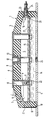
- Ein Ausführungsbeispiel der Erfindung ist in der Zeichnung dargestellt, die einen Schnitt durch eine erfindungsgemäße Vorrichtung zeigt, und wird im folgenden näher beschrieben.
- Eine Vorrichtung zur federnden Abstützung von Maschinen auf dem Boden weist ein glockenförmiges Gummibauteil 1 auf, das aus einer hohlzylindrischen Seitenwand 2 und einer im wesentlichen radial sich erstreckenden Stirnwand 3 besteht, die am oberen Ende der hohlzylindrischen Seitenwand 2 angeordnet ist. Am unteren Ende ist die hohlzylindrische Seitenwand 2 durch Vulkanisation mit einer radial sich erstreckenden, kreisförmigen Bodenplatte 4 aus Metall fest und dicht verbunden, die zusammen mit der Seitenwand 2 und der Stirnwand 3 eine Druckkammer 5 begrenzt.
- Die Stirnwand 3 besteht aus einem zentralen kreisscheibenförmigen Abschnitt 6, der koaxial zu der hohlzylindrischen Seitenwand 2 angeordnet ist und eine ebene Außenfläche aufweist, deren Durchmesser kleiner als der Durchmesser der Innenfläche des zentralen Stirnwandabschnittes ist, und einem kreisringförmigen Randabschnitt 7, der kegelstumpfförmig ausgebildet ist, den zentralen Stirnwandabschnitt 6 konzentrisch umgibt und ihn mit dem oberen Ende der hohlzylindrischen Seitenwand 2 verbindet. Die äußere und innere Mantellinie des kegelstumpfförmigen Randabschnittes schließen jeweils einen gleichen Winkel α bzw. β von etwa 15° mit der Ebene der Außenfläche bzw. der der Innenfläche des zentralen kreisförmigen Abschnittes 6 der Stirnwand 3 ein. Die Wanddicke des kegelstumpfförmigen Randabschnittes 7 ist konstant und geringer als die ebenfalls konstante Wanddicke des zentralen Stirnwandabschnittes 6. Der Wanddickenübergang zwischen dem kegelstumpfförmigen Randabschnitt 7 und dem kreisförmigen zentralen Abschnitt 6 erfolgt daher allmählich.
- Die Außenfläche des zentralen kreisförmigen Stirnwandabschnittes 6 liegt in einer Ebene, die vom oberen Ende der hohlzylindrischen Seitenwand 2 axial nach oben versetzt ist.
- Eine kreisscheibenförmige Lastträgerplatte 8 aus Metall, die den gleichen Durchmesser wie die Außenfläche des zentralen kreisförmigen Stirnwandabschnittes 6 aufweist, ist auf der Außenfläche des zentralen Stirnwandabschnittes 6 koaxial angeordnet. Die Lastträgerplatte 8 und die Bodenplatte 4 verlaufen parallel und sind koaxial zueinander. Auf ihrer der Außenfläche des zentralen Stirnwandabschnittes 5 zugekehrten Unterseite sind auf einer konzentrischen Kreislinie vier Metallfüße 9 mit jeweils einem Ende senkrecht angeschweißt, die einen Abstand von jeweils 90° auf der Kreislinie voneinander haben. Jeder Fuß 9 ist mit einem Endabschnitt, der an der Lastträgerplatte 8 befestigt ist, dicht durch ein jeweiliges Durchgangsloch 10 in dem zentralen kreisförmigen Stirnwandabschnitt 6 geführt und ragt in axialer Richtung aus dem zentralen kreisförmigen Stirnwandabschnitt hervor, so daß sich sein freies Ende in der Druckkammer 5 befindet. Jeder Fuß 9 besteht aus einem einen kreisförmigen Querschnitt aufweisenden Bolzen 11, der das an der Lastträgerplatte 8 angeschweißte Ende des Fußes und den durch das jeweilige Durchgangsloch 10 geführten Endabschnitt des Fußes aufweist, und einer in ein Sackloch, das in dem von der Lastträgerplatte 8 entfernten unteren Ende des jeweiligen Bolzens 11 koaxial angeordnet ist, eingedrehten Schraube 22, deren Kopf das freie Ende des Fußes 9 bildet. Sowohl die Lastträgerplatte 8 als auch die Füße 9 ist mit ihrer Unterseite bzw. sind mit ihren durch die Durchgangslöcher geführten Endabschnitten durch Vulkanisation mit dem zentralen kreisförmigen Abschnitt der Stirnwand 3 verbunden. Die freien Enden der Füße 9, welche durch die Köpfe der Schrauben 22 gebildet werden, haben im unverformten Zustand der Feder einen axialen Abstand von der Bodenplatte 4, der so bemessen ist, daß die freien Enden der Füße 9 mit der Bodenplatte 4 zur Anlage kommen, wenn eine auf die Lastträgerplatte 8 wirkende Axiallast einen vorbestimmten Grenzwert überschreitet. Eine Verformung der Stirnwand 3 nach innen aufgrund einer Axiallast, die auf die Lastträgerplatte 8 wirkt, wird somit durch Anlage der freien Enden der Füße 9 an der Bodenplatte 4 begrenzt. Wenn die Füße 9 auf der Bodenplatte 4 aufsitzen, kann die Lastträgerplatte 8 nicht mehr weiter nach unten gedrückt werden. Ein Zusammensacken oder ein seitliches Ausknicken der Vorrichtung infolge einer Überbelastung oder eines zu geringen Innendruckes wird bei der erfindungsgemäßen Vorrichtung zuverlässig vermieden.
- Die Lastträgerplatte 8 hat eine zentrale Öffnung 12, an die sich auf der Unterseite der Lastträgerplatte 8 die Gewindesackbohrung einer Hutmutter 13 aus Metall anschließt, die an der Unterseite der Lastträgerplatte 8 angeschweißt ist und in einem Sackloch in dem zentralen Stirnwandabschnitt 6 sitzt. Durch die Öffnung 12 kann eine zur Befestigung der Lastträgerplatte an der abzustützenden Maschine dienende Schraube in die Hutmutter 13 eingedreht werden. Auch die Hutmutter 13 ist mit der Stirnwand 3 durch Vulkanisation fest verbunden.
- Die Druckkammer 5 ist teilweise mit einer viskosen Flüssigkeit 14, wie z.B. Öl, gefüllt, wobei die Flüssigkeitsmenge so bemessen ist, daß die freien Enden der Füße 9 unterhalb des Flüssigkeitsspiegels sind, wenn das Gummibauteil 1 unverformt ist. Die Füße 9 weisen im Bereich ihrer freien Enden einen verbreiterten Abschnitt in Form einer kreisförmigen Lochplatte 15 auf, die mit Hilfe der Schrauben 22 an den unteren Enden der Bolzen 11 befestigt ist und sich in radialer Richtung unterhalb des Flüssigkeitsspiegels bis nahe an die Innenfläche der hohlzylindrischen Seitenwand 2 des Gummibauteiles 1 erstreckt. Bei einer Abwärts- und/oder Aufwärtsbewegung der Lochplatte 15 muß die Flüssigkeit 14 durch die Öffnungen 21 der Lochplatte 15 hindurchströmen und am Rand der Lochplatte durch die Öffnung 20 vorbeiströmen, wodurch der Bewegung ein Widerstand entgegengesetzt wird.
- Oberhalb des Flüssigkeitsspiegels befindet sich die Luft unter einem erhöhten Druck in der Druckkammer 5. Stöße und Schwingungen, die auf die Lastträgerplatte 8 wirken, werden somit nicht nur durch die elastische Deformation des Gummibauteiles 1, sondern auch durch die Kompression der in der Druckkammer befindlichen Luft und den Strömungswiderstand der Lochplatte 15 differenziert gedämpft und absorbiert.
- Die Luft und die Flüssigkeit 14 werden durch ein kombiniertes Luft-Flüssigkeitsventil 16, das in der hohlzylindrischen Seitenwand 2 angeordnet ist, in die Druckkammer 5 eingefüllt. Das Ventil 16 besteht im wesentlichen aus einer in einem Durchgangsloch in der Seitenwand 2 fest angeordneten Ventilhülse 23 aus Messing mit einem Innengewinde, in das ein Luftventil 24 lösbar und dicht eingeschraubt ist. Durch das Luftventil 24 kann mehr oder weniger Luft in die Druckkammer 5 gepumpt werden oder auch wieder ausströmen gelassen werden, so daß der Innendruck des Gummibauteiles variabel ist und den Bedürfnissen entsprechend angepaßt werden kann. Ohne das Luftventil 24 kann durch die Ventilhülse 23 Flüssigkeit in die Druckkammer 5 gefüllt oder aus ihr abgelassen werden.
- In der hohlzylindrischen Seitenwand 2 ist ein Metallzylinder 17 koaxial eingebettet und durch Vulkanisation mit der Seitenwand 2 fest verbunden. Der Metallzylinder 17 ist koaxial zu der Seitenwand 2 angeordnet und wird nur von einer dünnen Außenschicht der Seitenwand 2 umgeben. Der Metallzylinder 17 besteht aus einem Lochblech, das sich besser mit dem Gummibauteil 1 durch Vulkanisation verbindet als ein Blech ohne Löcher. Er hat die Aufgabe, das Gummibauteil vor Beschädigung durch seitliche Stöße, die durch von der abzustützenden Maschine herabfallende Metallteile oder durch unbeabsichtigtes Rammen der Vorrichtung mit einem Fahrzeug verursacht werden können, zu schützen.
- Das untere Ende der Seitenwand 2 ist formschlüssig in einer flachen Kreisringnut 18 aufgenommen, die in die Oberfläche der Bodenplatte 4 koaxial eingeformt ist. Durch Vulkanisation ist das in die Nut 18 ragende Ende der Seitenwand 2 mit der Oberfläche der Nut 18 fest verbunden. Durch diese Art der Befestigung des Gummibauteiles 1 an der Bodenplatte 4 wird sichergestellt, daß eine seitliche Relatiwerschiebung zwischen dem Gummibauteil 1 und der Bodenplatte 4, beispielsweise bei einer Überbeanspruchung der Vorrichtung oder auch bei seitlichen Stößen, ausgeschlossen ist.
- In der Mitte der Bodenplatte 4 ist eine mit einem Innengewinde versehene durchgehende Bohrung angeordnet, durch die ebenfalls Flüssigkeit in die Druckkammer 5 eingefüllt oder aus ihr abgelassen werden kann. In Betrieb ist die Bohrung in der Bodenplatte 4 durch eine Imbusschraube 25 dicht verschlossen.
- Die erfindungsgemäße Vorrichtung wird dadurch hergestellt, daß die zum Teil miteinander verschweißten Metallteile in einer Form angeordnet werden und der Gummi im flüssigen Zustand in die Form eingepreßt wird, wonach er ausvulkanisiert wird, wobei die von ihm benetzten Metallteile eine feste Gummi-Metallverbindung mit ihm eingehen. Dann werden die Flüssigkeit und Luft in die Druckkammer 5 eingefüllt, die dann dicht verschlossen wird.
Claims (11)
Priority Applications (1)
| Application Number | Priority Date | Filing Date | Title |
|---|---|---|---|
| AT87104931T ATE58576T1 (de) | 1986-04-04 | 1987-04-03 | Vorrichtung zur federnden abstuetzung von maschinen auf dem boden. |
Applications Claiming Priority (2)
| Application Number | Priority Date | Filing Date | Title |
|---|---|---|---|
| DE8609027U DE8609027U1 (de) | 1986-04-04 | 1986-04-04 | Kombinierte Luft-Gummifeder |
| DE8609027U | 1986-04-04 |
Publications (3)
| Publication Number | Publication Date |
|---|---|
| EP0240028A2 EP0240028A2 (de) | 1987-10-07 |
| EP0240028A3 EP0240028A3 (en) | 1989-02-22 |
| EP0240028B1 true EP0240028B1 (de) | 1990-11-22 |
Family
ID=6793293
Family Applications (1)
| Application Number | Title | Priority Date | Filing Date |
|---|---|---|---|
| EP87104931A Expired - Lifetime EP0240028B1 (de) | 1986-04-04 | 1987-04-03 | Vorrichtung zur federnden Abstützung von Maschinen auf dem Boden |
Country Status (3)
| Country | Link |
|---|---|
| EP (1) | EP0240028B1 (de) |
| AT (1) | ATE58576T1 (de) |
| DE (2) | DE8609027U1 (de) |
Cited By (1)
| Publication number | Priority date | Publication date | Assignee | Title |
|---|---|---|---|---|
| CN103062579A (zh) * | 2012-12-25 | 2013-04-24 | 南京航空航天大学 | 缓冲支撑结构 |
Families Citing this family (3)
| Publication number | Priority date | Publication date | Assignee | Title |
|---|---|---|---|---|
| DE3935499C2 (de) * | 1989-10-25 | 2000-12-28 | Gmt Gummi Metall Technik Gmbh | Kombinierte Gummi-Gasfeder |
| DE4213043C2 (de) * | 1992-04-21 | 1994-03-10 | Continental Ag | Hydropneumatisches Dämpfer-Federelement |
| ATE343742T1 (de) * | 2002-06-03 | 2006-11-15 | Contitech Luftfedersyst Gmbh | Hydrofeder als primärfeder in schienenfahrzeugen |
Family Cites Families (7)
| Publication number | Priority date | Publication date | Assignee | Title |
|---|---|---|---|---|
| DE1090108B (de) * | 1956-09-19 | 1960-09-29 | Daimler Benz Ag | Luftfederung, insbesondere fuer Lastkraftwagen od. ae. Fahrzeuge |
| DE1285792B (de) * | 1966-11-07 | 1968-12-19 | Continental Gummi Werke Ag | Luftfeder mit einem verformbare Wandungen und verstaerkte Wuelste aufweisenden Balg |
| US3836134A (en) * | 1973-03-19 | 1974-09-17 | Wright Barry Corp | Pneumatic isolator |
| DE2712641A1 (de) * | 1977-03-23 | 1978-09-28 | Phoenix Gummiwerke Ag | Elastisches lager fuer kraftfahrzeugmotore |
| IT1165137B (it) * | 1979-06-29 | 1987-04-22 | Gomma Antivibranti Applic | Sopporto ammortizzante per la sospensione di un corpo oscillante ad una struttura di sopporto,particolarmente per la sospensione del motore al telaio di un autoveicolo |
| IT1150821B (it) * | 1982-04-09 | 1986-12-17 | Gomma Antivibranti Applic | Supporto ammortizzante |
| DE3239963A1 (de) * | 1982-09-09 | 1984-05-24 | Continental Gummi-Werke Ag, 3000 Hannover | Hydraulisch gedaempftes elastisches lager |
-
1986
- 1986-04-04 DE DE8609027U patent/DE8609027U1/de not_active Expired
-
1987
- 1987-04-03 AT AT87104931T patent/ATE58576T1/de not_active IP Right Cessation
- 1987-04-03 EP EP87104931A patent/EP0240028B1/de not_active Expired - Lifetime
- 1987-04-03 DE DE8787104931T patent/DE3766274D1/de not_active Expired - Lifetime
Cited By (1)
| Publication number | Priority date | Publication date | Assignee | Title |
|---|---|---|---|---|
| CN103062579A (zh) * | 2012-12-25 | 2013-04-24 | 南京航空航天大学 | 缓冲支撑结构 |
Also Published As
| Publication number | Publication date |
|---|---|
| EP0240028A3 (en) | 1989-02-22 |
| DE3766274D1 (de) | 1991-01-03 |
| DE8609027U1 (de) | 1986-05-22 |
| ATE58576T1 (de) | 1990-12-15 |
| EP0240028A2 (de) | 1987-10-07 |
Similar Documents
| Publication | Publication Date | Title |
|---|---|---|
| EP0149081B1 (de) | Elastisches Lager mit einem hydraulischen Dämpfer | |
| DE3619626C2 (de) | ||
| DE2353868C3 (de) | Kombinierte Gummi-Gasfeder | |
| DE3919775C2 (de) | Abstützlager | |
| DE3125907A1 (de) | Daempfungselement fuer die aufhaengung eines schwingenden koerpers an einer tragkonstruktion | |
| DE102015217727A1 (de) | Anschlagkappe | |
| DE69008264T2 (de) | Verbesserungen an hydraulischen Schwingungsdämpfern. | |
| DE3106690A1 (de) | Gummifeder fuer die elastische lagerung von maschinen | |
| DE2435876A1 (de) | Stossdaempfer | |
| DE3342300C2 (de) | ||
| DE9116366U1 (de) | Druckmaschinenzylinder mit Schwingungsdämpfung | |
| DE3405907C2 (de) | ||
| DE10144163C1 (de) | Federbein mit höheneinstellbarem Federteller | |
| EP0351737B1 (de) | Hydraulisch dämpfendes Motorlager | |
| EP0240028B1 (de) | Vorrichtung zur federnden Abstützung von Maschinen auf dem Boden | |
| DE2616258A1 (de) | Gummilager mit hydraulischer daempfung | |
| EP0520143B1 (de) | Steuerbares Motorlager | |
| DE2337665C3 (de) | Hydraulischer Zweirohr-Schwingungsdampfer, insbesondere fur Fahrzeuge | |
| EP0734888B1 (de) | Oberes Federbeinstützlager für Radaufhängungen in einem Kraftfahrzeug | |
| DE19527260A1 (de) | Hydraulisch dämpfendes Motorlager | |
| DE69907282T2 (de) | Obere halterung einer luftfeder | |
| DE112019003332T5 (de) | Fluidgefüllte vibrationsdämpfungsvorrichtung | |
| DE3233456C2 (de) | Hydraulisch gedämpftes elastisches Lager | |
| EP0528253B1 (de) | Hydraulisch dämpfendes Stützlager für Fahrwerksteile in Kraftfahrzeugen | |
| DE3522333C2 (de) |
Legal Events
| Date | Code | Title | Description |
|---|---|---|---|
| PUAI | Public reference made under article 153(3) epc to a published international application that has entered the european phase |
Free format text: ORIGINAL CODE: 0009012 |
|
| AK | Designated contracting states |
Kind code of ref document: A2 Designated state(s): AT BE CH DE ES FR GB GR IT LI LU NL SE |
|
| PUAL | Search report despatched |
Free format text: ORIGINAL CODE: 0009013 |
|
| AK | Designated contracting states |
Kind code of ref document: A3 Designated state(s): AT BE CH DE ES FR GB GR IT LI LU NL SE |
|
| 17P | Request for examination filed |
Effective date: 19890323 |
|
| 17Q | First examination report despatched |
Effective date: 19890721 |
|
| GRAA | (expected) grant |
Free format text: ORIGINAL CODE: 0009210 |
|
| AK | Designated contracting states |
Kind code of ref document: B1 Designated state(s): AT BE CH DE ES FR GB GR IT LI LU NL SE |
|
| PG25 | Lapsed in a contracting state [announced via postgrant information from national office to epo] |
Ref country code: GR Free format text: LAPSE BECAUSE OF FAILURE TO SUBMIT A TRANSLATION OF THE DESCRIPTION OR TO PAY THE FEE WITHIN THE PRESCRIBED TIME-LIMIT Effective date: 19901122 Ref country code: BE Effective date: 19901122 Ref country code: IT Free format text: LAPSE BECAUSE OF FAILURE TO SUBMIT A TRANSLATION OF THE DESCRIPTION OR TO PAY THE FEE WITHIN THE PRESCRIBED TIME-LIMIT;WARNING: LAPSES OF ITALIAN PATENTS WITH EFFECTIVE DATE BEFORE 2007 MAY HAVE OCCURRED AT ANY TIME BEFORE 2007. THE CORRECT EFFECTIVE DATE MAY BE DIFFERENT FROM THE ONE RECORDED. Effective date: 19901122 Ref country code: SE Effective date: 19901122 |
|
| REF | Corresponds to: |
Ref document number: 58576 Country of ref document: AT Date of ref document: 19901215 Kind code of ref document: T |
|
| GBT | Gb: translation of ep patent filed (gb section 77(6)(a)/1977) | ||
| REF | Corresponds to: |
Ref document number: 3766274 Country of ref document: DE Date of ref document: 19910103 |
|
| PG25 | Lapsed in a contracting state [announced via postgrant information from national office to epo] |
Ref country code: ES Free format text: LAPSE BECAUSE OF FAILURE TO SUBMIT A TRANSLATION OF THE DESCRIPTION OR TO PAY THE FEE WITHIN THE PRESCRIBED TIME-LIMIT Effective date: 19910305 |
|
| ET | Fr: translation filed | ||
| PG25 | Lapsed in a contracting state [announced via postgrant information from national office to epo] |
Ref country code: AT Effective date: 19910403 |
|
| PG25 | Lapsed in a contracting state [announced via postgrant information from national office to epo] |
Ref country code: LU Free format text: LAPSE BECAUSE OF NON-PAYMENT OF DUE FEES Effective date: 19910430 |
|
| PLBE | No opposition filed within time limit |
Free format text: ORIGINAL CODE: 0009261 |
|
| STAA | Information on the status of an ep patent application or granted ep patent |
Free format text: STATUS: NO OPPOSITION FILED WITHIN TIME LIMIT |
|
| 26N | No opposition filed | ||
| REG | Reference to a national code |
Ref country code: CH Ref legal event code: PUEA Free format text: ADOLF FAEHNLE GMBH & CO. KG;BILZ SCHWINGUNGSTECHNIK GMBH TRANSFER- BILZ SCHWINGUNGSTECHNIK GMBH;FAEHNLE TECHNIC GMBH |
|
| REG | Reference to a national code |
Ref country code: GB Ref legal event code: 732E |
|
| REG | Reference to a national code |
Ref country code: FR Ref legal event code: TQ |
|
| REG | Reference to a national code |
Ref country code: GB Ref legal event code: IF02 |
|
| PGFP | Annual fee paid to national office [announced via postgrant information from national office to epo] |
Ref country code: FR Payment date: 20030129 Year of fee payment: 17 |
|
| PGFP | Annual fee paid to national office [announced via postgrant information from national office to epo] |
Ref country code: GB Payment date: 20030320 Year of fee payment: 17 |
|
| PGFP | Annual fee paid to national office [announced via postgrant information from national office to epo] |
Ref country code: NL Payment date: 20030429 Year of fee payment: 17 |
|
| PGFP | Annual fee paid to national office [announced via postgrant information from national office to epo] |
Ref country code: DE Payment date: 20030528 Year of fee payment: 17 |
|
| PGFP | Annual fee paid to national office [announced via postgrant information from national office to epo] |
Ref country code: CH Payment date: 20030530 Year of fee payment: 17 |
|
| PG25 | Lapsed in a contracting state [announced via postgrant information from national office to epo] |
Ref country code: GB Free format text: LAPSE BECAUSE OF NON-PAYMENT OF DUE FEES Effective date: 20040403 |
|
| PG25 | Lapsed in a contracting state [announced via postgrant information from national office to epo] |
Ref country code: CH Free format text: LAPSE BECAUSE OF NON-PAYMENT OF DUE FEES Effective date: 20040430 Ref country code: LI Free format text: LAPSE BECAUSE OF NON-PAYMENT OF DUE FEES Effective date: 20040430 |
|
| PG25 | Lapsed in a contracting state [announced via postgrant information from national office to epo] |
Ref country code: NL Free format text: LAPSE BECAUSE OF NON-PAYMENT OF DUE FEES Effective date: 20041101 |
|
| PG25 | Lapsed in a contracting state [announced via postgrant information from national office to epo] |
Ref country code: DE Free format text: LAPSE BECAUSE OF NON-PAYMENT OF DUE FEES Effective date: 20041103 |
|
| GBPC | Gb: european patent ceased through non-payment of renewal fee | ||
| REG | Reference to a national code |
Ref country code: CH Ref legal event code: PL |
|
| PG25 | Lapsed in a contracting state [announced via postgrant information from national office to epo] |
Ref country code: FR Free format text: LAPSE BECAUSE OF NON-PAYMENT OF DUE FEES Effective date: 20041231 |
|
| NLV4 | Nl: lapsed or anulled due to non-payment of the annual fee |
Effective date: 20041101 |
|
| REG | Reference to a national code |
Ref country code: FR Ref legal event code: ST |