EP0239399A2 - Plattenbearbeitungssystem - Google Patents
Plattenbearbeitungssystem Download PDFInfo
- Publication number
- EP0239399A2 EP0239399A2 EP87302614A EP87302614A EP0239399A2 EP 0239399 A2 EP0239399 A2 EP 0239399A2 EP 87302614 A EP87302614 A EP 87302614A EP 87302614 A EP87302614 A EP 87302614A EP 0239399 A2 EP0239399 A2 EP 0239399A2
- Authority
- EP
- European Patent Office
- Prior art keywords
- work piece
- sheet material
- fluid
- pad
- support apparatus
- Prior art date
- Legal status (The legal status is an assumption and is not a legal conclusion. Google has not performed a legal analysis and makes no representation as to the accuracy of the status listed.)
- Withdrawn
Links
Images



Classifications
-
- B—PERFORMING OPERATIONS; TRANSPORTING
- B23—MACHINE TOOLS; METAL-WORKING NOT OTHERWISE PROVIDED FOR
- B23C—MILLING
- B23C3/00—Milling particular work; Special milling operations; Machines therefor
-
- Y—GENERAL TAGGING OF NEW TECHNOLOGICAL DEVELOPMENTS; GENERAL TAGGING OF CROSS-SECTIONAL TECHNOLOGIES SPANNING OVER SEVERAL SECTIONS OF THE IPC; TECHNICAL SUBJECTS COVERED BY FORMER USPC CROSS-REFERENCE ART COLLECTIONS [XRACs] AND DIGESTS
- Y10—TECHNICAL SUBJECTS COVERED BY FORMER USPC
- Y10T—TECHNICAL SUBJECTS COVERED BY FORMER US CLASSIFICATION
- Y10T408/00—Cutting by use of rotating axially moving tool
- Y10T408/44—Cutting by use of rotating axially moving tool with means to apply transient, fluent medium to work or product
-
- Y—GENERAL TAGGING OF NEW TECHNOLOGICAL DEVELOPMENTS; GENERAL TAGGING OF CROSS-SECTIONAL TECHNOLOGIES SPANNING OVER SEVERAL SECTIONS OF THE IPC; TECHNICAL SUBJECTS COVERED BY FORMER USPC CROSS-REFERENCE ART COLLECTIONS [XRACs] AND DIGESTS
- Y10—TECHNICAL SUBJECTS COVERED BY FORMER USPC
- Y10T—TECHNICAL SUBJECTS COVERED BY FORMER US CLASSIFICATION
- Y10T409/00—Gear cutting, milling, or planing
- Y10T409/30—Milling
- Y10T409/303976—Milling with means to control temperature or lubricate
- Y10T409/304032—Cutter or work
-
- Y—GENERAL TAGGING OF NEW TECHNOLOGICAL DEVELOPMENTS; GENERAL TAGGING OF CROSS-SECTIONAL TECHNOLOGIES SPANNING OVER SEVERAL SECTIONS OF THE IPC; TECHNICAL SUBJECTS COVERED BY FORMER USPC CROSS-REFERENCE ART COLLECTIONS [XRACs] AND DIGESTS
- Y10—TECHNICAL SUBJECTS COVERED BY FORMER USPC
- Y10T—TECHNICAL SUBJECTS COVERED BY FORMER US CLASSIFICATION
- Y10T409/00—Gear cutting, milling, or planing
- Y10T409/30—Milling
- Y10T409/30868—Work support
-
- Y—GENERAL TAGGING OF NEW TECHNOLOGICAL DEVELOPMENTS; GENERAL TAGGING OF CROSS-SECTIONAL TECHNOLOGIES SPANNING OVER SEVERAL SECTIONS OF THE IPC; TECHNICAL SUBJECTS COVERED BY FORMER USPC CROSS-REFERENCE ART COLLECTIONS [XRACs] AND DIGESTS
- Y10—TECHNICAL SUBJECTS COVERED BY FORMER USPC
- Y10T—TECHNICAL SUBJECTS COVERED BY FORMER US CLASSIFICATION
- Y10T83/00—Cutting
- Y10T83/263—With means to apply transient nonpropellant fluent material to tool or work
-
- Y—GENERAL TAGGING OF NEW TECHNOLOGICAL DEVELOPMENTS; GENERAL TAGGING OF CROSS-SECTIONAL TECHNOLOGIES SPANNING OVER SEVERAL SECTIONS OF THE IPC; TECHNICAL SUBJECTS COVERED BY FORMER USPC CROSS-REFERENCE ART COLLECTIONS [XRACs] AND DIGESTS
- Y10—TECHNICAL SUBJECTS COVERED BY FORMER USPC
- Y10T—TECHNICAL SUBJECTS COVERED BY FORMER US CLASSIFICATION
- Y10T83/00—Cutting
- Y10T83/748—With work immobilizer
Definitions
- This invention relates to a system for machining resilient sheet material and in particular, but not exclusively, to apparatus for supporting resilient sheet material during a machining operation.
- Profiled sheet metal flats or blanks are commonly fabricated in the aircraft industry by routing around a profile to produce a component of the required shape.
- a stack of sheet metal blanks are drilled and riveted together, clamped to a sacrificial base, loaded onto the horizontal table of a numerically - controlled vertical spindle routing machine and routed along the programmed profiles.
- the sheets are separated, part marked and moved to a further work station.
- the profile path, nesting of the various profiles and attachment and release of the stacked sheets are performed under computer control.
- work piece support apparatus for supporting resilient sheet material during a machining operation, for example routing, comprising pad means provided adjacent each side of said sheet material surrounding the region of the material to be machined, and fluid supply means for interposing a flow of fluid at a relatively high pressure between each pad means and the adjacent region of the sheet material.
- the sheet material may comprise a single sheet or a plurality of stacked sheets.
- the sheet is fluid pressure supported against excessive movement during the machining process; thus single sheets and stacks of sheets may be machined without the need for a sacrificial support.
- each of said pad means includes a pressure pad positioned adjacent the surface of the work piece and one or more fluid chambers formed within said pad means, said pressure pad including fluid outlet openings communicating with said chamber or chambers, said chamber or chambers including fluid inlet means for connection to said fluid supply means.
- said work piece support means includes clamping means for locating and supporting said work piece over at least a portion of the periphery of said work piece.
- a routing machine having a machine tool spindle mounted for rotation about a generally horizontal axis and work piece support means for supporting sheet material in a generally vertical plane, said support means including fluid pressure pad means adjacent each side of said sheet material generally surrounding the region of the material to be machined and fluid supply means for interposing fluid at pressure between said pads and the respective adjacent surface of the sheet material.
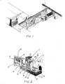
- a multi-axis single spindle high speed routing machine 1 for routing or profile machining sheet material under computerised numerical control and in which the work piece 2, ie, the resilient sheet material, is positioned in a generally vertical plane and the spindle or routing tool 3, is mounted about a generally horizontal axis 4.
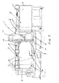
- the work piece 2 is loaded manually in the loading area 5, as indicated in Figures 2 and 7 and as hereinafter described and transferred by means of an overhead transfer mechanism 13 and indexed into the working area 7 where it is clamped for the machining operation.
- the work piece 2 is automatically transferred from the working area 7 back to the loading area 5 for manual unloading by the operator.
- each work piece 2 may comprise a single sheet or a stack of sheets up to a maximum of five.
- the routing machine comprises a fixed bed 8 to which are mounted a pair of guide bars 9 for slidably supporting a platen 10 for movement in the x-axis, ie, the fore and aft direction, and which itself supports a portal frame 11. Additionally mounted upon the fixed bed 8 is the support structure 6 and 12 for supporting the longitudinally extending work piece clamping and transfer mechanism 13 which extends rearwards to overlie and form an integral part of the loading area 5.
- the portal frame 11 comprises two vertical pillars 14 and 14i bridged by a fabricated horizontal beam portion 15.
- Each vertical pillar 14 and 14i includes a pair of vertical guide bars 16 slidably engaging platens 17 and 17i respectively for movement in the Y-axis, ie, the vertical direction.
- Each platen 17 and 17i includes an underslung double nut assembly (not shown) engaging individual recirculating ball lead screws 18 driven by a common Y-axis drive motor 19 mounted on the horizontal beam portion 15.
- the respective left hand platen 17 and right hand platen 17i are constrained to move synchronously in the Y-axis by means of an interconnection between the respective ball lead screws 18 in the form of a pulley and drive belt assembly 20 contained within the beam portion 15.
- Each platen 17 and 17i includes a pair of horizontal guide bars (not shown).
- the left hand platen 17 includes a pair of horizontally disposed guide bars (not shown) which slidably engage a light fabricated platen 21 on which is mounted the left hand hydrostatic pressure pad assembly 22 for movement in the Z-axis.
- the right hand platen 17i includes a pair of horizontally disposed guide bars (not shown) which support a cast aluminium housing 23 carrying the horizontally disposed high speed machine tool spindle 3 for movement in the Z-axis. Both the platen 21 and the machine tool spindle 3 are driven in the Z-axis by means of separate ball lead screw arrangements, not shown for reasons of clarity.
- a datum hydrostatic pressure pad 24R is located to an outrigger support mounting 25 mounted directly on the Y-axis platen 17i, and the respective hydrostatic pressure pads 24L and 24R, the housing 23 and the machine tool spindle 3 are symmetrically disposed about the horizontal axis 4.
- the support mounting, 25 is arranged internally to accommodate lateral movement of the machine tool spindle 3 along the horizontal axis 4.
- the datum hydrostatic pressure pad 24R being mounted, as stated above, on the Y-axis platen 17i will be constrained to move only in the Y-axis, that is, in a vertically upwards or downwards direction. This pad will therefore be fixed in the Z-axis relative to the work piece being machined such that the datum face 26 will be at a fixed pre-set position to provide a gap of 0.25 mm (.01 inches) with the adjacent work piece datum face 27.
- the hydrostatic pressure pad assembly 22 being movable, as previously stated, in the z-axis, is programmed to maintain a similar gap of 0.25mm (.01 inches) between the pad face 28 and the adjacent work piece face 29. The amount of pad movement in the Z-axis to achieve this desired gap is determined by the overall work piece thickness in any particular machining operation.
- the hydrostatic pressure body assemblies 22 and 25 each includes a porting system 30 and 31 respectively for supplying a suitable hydrostatic fluid at pressure to each respective hydrostatic pressure pad 24L and 24R.
- the hydrostatic pressure pads 24L and 24R are generally rectangular and include a centralised vertical slot 32 shaped to accommodate and give clearance to the machine tool spindle 3.
- the downwardly extending slot 32 additionally allows swarf and coolant to fall freely away during machining.
- the pad also includes, on the rearward face four recesses 33 and 34 which interconnect with the porting system 30 and 31, each recess defining a plenum chamber for supplying hydrostatic fluid to an array of hole pairs 35 grouped as shown across the surface of the pad.
- Each pair of holes extend towards the outer face of the plate terminating in a counterbore 36 to provide improved fluid dispersion across the pad face.
- a work piece sheet 2 or stack of sheets is loaded manually in the loading area 5 and clamped at its horizontal upper edge by a pair of hydraulically actuated spring loaded clamps 37 incorporated into the overhead transfer system 13 by which means the sheet is transferred into the working area 7 and clamped by means of four hydraulic clamps 38 at its upper longitudinal edge and three hydraulic clamps 39 at its lower longitudinal edge.
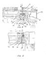
- the overall thickness of the work piece is sensed by a suitably located linear voltage displacement transducer and the Z-axis actuator controlling the hydrostatic pressure pad assembly 22 is operated to place the pad face 28 - at the correct gap with respect to the adjacent work piece face 29 - as shown in Figure 8.
- This Figure illustrates the lateral spaced relationship between the upper and lower clamps and the hydrostatic pressure pads 24.
- the upper clamp 37 depicted is that for the sheet transfer phase but is equally applicable to the upper clamps 38 within the working area 7.
- the serrated faces 40 and 41 on the upper and lower clamps define the vertical datum face 27 of the work piece 2 and ensure the correct working gap with the fixed pad datum face 26 as previously described.
- Sheet thickness tolerances or the total overall thickness of a multiple sheet work piece are sensed by the linear voltage displacement transducer 42 and the left hand pressure pad assembly 22 adjusted accordingly to achieve the desired gap at the pad face 28.
- the upper and lower clamps are therefore adjustable such that the serrated jaw remote from the datum face 27 is movable to accommodate variable work piece thicknesses. Typical clamp arrangement though not described in detail here are illustrated in Figures 9-12 inclusive.
- the hydrostatic fluid pump (not shown) is operated to supply fluid at high pressure, typically 150lbs/sq inch to each respective pressure pad 24L and 24R the fluid being ejected through the hole pairs 35 to support the sheet or sheets against movement in the Z direction during the machining process, by means of a supporting fluid surface layer.
- the hydrostatic pressure pad assembly moves simultaneously with the machine tool spindle, throughout the machining cycle providing pressurised fluid support in the immediate vicinity of the spindle, the combination of movements in the X, Y and Z axes all controlled by a computer in accordance with set pre-programmed instructions.
- the hydrostatic fluid in addition to its support function simultaneously acts as a coolant at the cutting face and a swarf dispersal medium.
- the machine further includes an underfloor coolant and swarf removal system.
- a sheet profile manufacturing system can be provided with a through feed system whereby the completed work piece can be passed forwards for further processing at an immediately adjacent work station.
- hydrostatic work piece support system and the multi-sheet routing system of the present invention offer the following advantages:-
Landscapes
- Engineering & Computer Science (AREA)
- Mechanical Engineering (AREA)
- Jigs For Machine Tools (AREA)
- Grinding Of Cylindrical And Plane Surfaces (AREA)
Applications Claiming Priority (2)
| Application Number | Priority Date | Filing Date | Title |
|---|---|---|---|
| GB868607645A GB8607645D0 (en) | 1986-03-27 | 1986-03-27 | Sheet material machining system |
| GB8607645 | 1986-03-27 |
Publications (2)
| Publication Number | Publication Date |
|---|---|
| EP0239399A2 true EP0239399A2 (de) | 1987-09-30 |
| EP0239399A3 EP0239399A3 (de) | 1989-11-23 |
Family
ID=10595338
Family Applications (1)
| Application Number | Title | Priority Date | Filing Date |
|---|---|---|---|
| EP87302614A Withdrawn EP0239399A3 (de) | 1986-03-27 | 1987-03-26 | Plattenbearbeitungssystem |
Country Status (7)
| Country | Link |
|---|---|
| US (1) | US4787787A (de) |
| EP (1) | EP0239399A3 (de) |
| JP (1) | JPS6322242A (de) |
| AU (1) | AU597343B2 (de) |
| CA (1) | CA1277529C (de) |
| GB (1) | GB8607645D0 (de) |
| NO (1) | NO871286L (de) |
Families Citing this family (7)
| Publication number | Priority date | Publication date | Assignee | Title |
|---|---|---|---|---|
| US5088181A (en) * | 1990-10-09 | 1992-02-18 | The Boeing Company | Sheet metal part machining system |
| US5342067A (en) * | 1993-08-09 | 1994-08-30 | Corning Incorporated | Method and apparatus for machining substrate plates for magnetic memory disks |
| DE4343327C2 (de) * | 1993-12-18 | 1997-09-11 | Oxytechnik Ges Systemtech | Vorrichtung zum Bearbeiten von Werkstückkanten |
| US7869184B2 (en) * | 2005-11-30 | 2011-01-11 | Lam Research Corporation | Method of determining a target mesa configuration of an electrostatic chuck |
| FR3031923B1 (fr) * | 2015-01-23 | 2017-08-25 | Dassault Aviat | Installation de surfacage comprenant un conduit fluidique debouchant dans un espace central entre des aretes de coupe, et procede associe |
| ES2632166B1 (es) | 2016-02-08 | 2018-05-08 | Manuel Torres Martinez | Dispositivo de mecanizado de superficies laminares curvas |
| CN119407706B (zh) * | 2024-11-04 | 2026-01-16 | 中航西安飞机工业集团股份有限公司 | 一种用于飞机零件的夹持装置 |
Family Cites Families (10)
| Publication number | Priority date | Publication date | Assignee | Title |
|---|---|---|---|---|
| US3488674A (en) * | 1968-05-23 | 1970-01-06 | Gen Res Inc | Apparatus for operating on a normally limp surface,particularly on the edge of an envelope |
| AT307005B (de) * | 1970-09-01 | 1973-05-10 | Schelling & Co | Werkstücktisch zur Auflage und zum Verschieben von Holz- oder Kunststoffplatten |
| US3964355A (en) * | 1973-08-06 | 1976-06-22 | U.S. Amada, Ltd. | Air cushion sheet support |
| US3979984A (en) * | 1973-08-06 | 1976-09-14 | U.S. Amada, Ltd. | Contouring apparatus |
| SE424608B (sv) * | 1977-09-27 | 1982-08-02 | Bert Larsson | Borr- coh fresmaskin for monsterkort |
| FR2412385A1 (fr) * | 1977-12-22 | 1979-07-20 | Crouzet Sa | Machine a scier des barreaux de silicium |
| DE2817218A1 (de) * | 1978-04-20 | 1979-10-31 | Trumpf Maschinen Ag | Werkzeugmaschine |
| DE3404555A1 (de) * | 1984-02-09 | 1985-08-14 | Messerschmitt-Bölkow-Blohm GmbH, 2800 Bremen | Niederhalter fuer werkzeugmaschinen |
| FR2570012B1 (fr) * | 1984-09-12 | 1986-12-05 | Aerospatiale | Dispositif d'usinage pourvu d'un presse-flan lie a l'outil et presse-flan pour un tel dispositif |
| DE3443398A1 (de) * | 1984-11-28 | 1986-05-28 | Maschinenfabrik Reichenbacher GmbH, 8635 Dörfles-Esbach | Niederhalter fuer werkstuecke, insbesondere an fraesmaschinen |
-
1986
- 1986-03-27 GB GB868607645A patent/GB8607645D0/en active Pending
-
1987
- 1987-03-26 EP EP87302614A patent/EP0239399A3/de not_active Withdrawn
- 1987-03-26 CA CA000533014A patent/CA1277529C/en not_active Expired - Fee Related
- 1987-03-26 NO NO871286A patent/NO871286L/no unknown
- 1987-03-26 AU AU70678/87A patent/AU597343B2/en not_active Ceased
- 1987-03-27 JP JP62073961A patent/JPS6322242A/ja active Pending
- 1987-03-27 US US07/031,053 patent/US4787787A/en not_active Expired - Fee Related
Also Published As
| Publication number | Publication date |
|---|---|
| NO871286D0 (no) | 1987-03-26 |
| AU7067887A (en) | 1987-10-01 |
| AU597343B2 (en) | 1990-05-31 |
| GB8607645D0 (en) | 1986-04-30 |
| NO871286L (no) | 1987-09-28 |
| CA1277529C (en) | 1990-12-11 |
| EP0239399A3 (de) | 1989-11-23 |
| JPS6322242A (ja) | 1988-01-29 |
| US4787787A (en) | 1988-11-29 |
Similar Documents
| Publication | Publication Date | Title |
|---|---|---|
| KR100209920B1 (ko) | 공구조립체의 양쪽에서 개별 제어식 파지 이송 수단에 의해 파지된 공작물을 가공하기 위한 다중 스핀들 기계 | |
| EP0455095B1 (de) | Kombinierte Maschine zur Verarbeitung von einzelnen oder gestapelten Holzplatten oder ähnlichem Material | |
| EP2708312B1 (de) | Bearbeitungszentrum | |
| EP3616832B1 (de) | Werkzeugmaschine, insbesondere drehmaschine | |
| KR100911764B1 (ko) | 조각과 절단 및 브이컷 겸용 가공기 | |
| EP2732910A1 (de) | Rotierender werkstückspindelstock | |
| US4787787A (en) | Sheet material machining system | |
| CN115488640A (zh) | 一种加工斜孔的开自动数控铣床 | |
| KR20000023016A (ko) | 2개의 스핀들 헤드를 구비한 공작 기계 | |
| CN218362498U (zh) | 一种圆柱形工件两端倒角机 | |
| US6585463B1 (en) | Milling apparatus | |
| US3979984A (en) | Contouring apparatus | |
| US5187846A (en) | Pallet changer | |
| KR100633559B1 (ko) | 항공기 동체용 판넬 드릴링 장치 | |
| US6062117A (en) | Machining apparatus for works having non-circular curves | |
| CN218363271U (zh) | 一种多自由度的钻铣机 | |
| JPH10244426A (ja) | ピストンリングの複合加工装置 | |
| JP2767002B2 (ja) | 両面機械加工装置 | |
| CN211916290U (zh) | 龙门结构及数控机床 | |
| CN115446600A (zh) | 四面侧铣数控六面钻 | |
| CN114905092A (zh) | 一种用于对齿轮毛坯进行加工的锯床 | |
| CN111152290B (zh) | 一种利用铝板加工的印刷电路板钻床 | |
| CN212043674U (zh) | 一种夹具装置及钻孔冲压机 | |
| KR940003826Y1 (ko) | 다중가공헤드를 구비한 방전가공기 | |
| JPH11333534A (ja) | 板材位置決め装置、この板材位置決め装置の使用方法、板材加工機 |
Legal Events
| Date | Code | Title | Description |
|---|---|---|---|
| PUAI | Public reference made under article 153(3) epc to a published international application that has entered the european phase |
Free format text: ORIGINAL CODE: 0009012 |
|
| AK | Designated contracting states |
Kind code of ref document: A2 Designated state(s): DE ES FR GB GR IT SE |
|
| RAP1 | Party data changed (applicant data changed or rights of an application transferred) |
Owner name: MARWIN PRODUCTION MACHINES LIMITED Owner name: BRITISH AEROSPACE PUBLIC LIMITED COMPANY |
|
| PUAL | Search report despatched |
Free format text: ORIGINAL CODE: 0009013 |
|
| AK | Designated contracting states |
Kind code of ref document: A3 Designated state(s): DE ES FR GB GR IT SE |
|
| RHK1 | Main classification (correction) |
Ipc: B23Q 3/06 |
|
| 17P | Request for examination filed |
Effective date: 19900522 |
|
| 17Q | First examination report despatched |
Effective date: 19910328 |
|
| ITF | It: translation for a ep patent filed | ||
| RAP3 | Party data changed (applicant data changed or rights of an application transferred) |
Owner name: MARWIN PRODUCTION MACHINES LIMITED Owner name: BRITISH AEROSPACE PUBLIC LIMITED COMPANY |
|
| STAA | Information on the status of an ep patent application or granted ep patent |
Free format text: STATUS: THE APPLICATION IS DEEMED TO BE WITHDRAWN |
|
| 18D | Application deemed to be withdrawn |
Effective date: 19921001 |
|
| RIN1 | Information on inventor provided before grant (corrected) |
Inventor name: BAYES, M.G. Inventor name: HOPWELL, E. |