EP0239083B1 - Flache Lochmaske für eine Farbbildröhre - Google Patents
Flache Lochmaske für eine Farbbildröhre Download PDFInfo
- Publication number
- EP0239083B1 EP0239083B1 EP87104353A EP87104353A EP0239083B1 EP 0239083 B1 EP0239083 B1 EP 0239083B1 EP 87104353 A EP87104353 A EP 87104353A EP 87104353 A EP87104353 A EP 87104353A EP 0239083 B1 EP0239083 B1 EP 0239083B1
- Authority
- EP
- European Patent Office
- Prior art keywords
- mask
- apertures
- horizontal
- pitch
- center
- Prior art date
- Legal status (The legal status is an assumption and is not a legal conclusion. Google has not performed a legal analysis and makes no representation as to the accuracy of the status listed.)
- Expired - Lifetime
Links
Images


Classifications
-
- H—ELECTRICITY
- H01—ELECTRIC ELEMENTS
- H01J—ELECTRIC DISCHARGE TUBES OR DISCHARGE LAMPS
- H01J29/00—Details of cathode-ray tubes or of electron-beam tubes of the types covered by group H01J31/00
- H01J29/02—Electrodes; Screens; Mounting, supporting, spacing or insulating thereof
- H01J29/06—Screens for shielding; Masks interposed in the electron stream
- H01J29/07—Shadow masks for colour television tubes
- H01J29/076—Shadow masks for colour television tubes characterised by the shape or distribution of beam-passing apertures
Definitions
- This invention concerns tension mask color cathode ray tubes, and more particularly, relates to an improved front assembly having a mask with an aperture pattern which reduces beamlet degrouping errors.
- Beam degrouping errors can result from such factors as errors in the geometries of the substantially flat faceplate and the associated planar mask, the in-line condition of the three beams, and the influence of the self-converging yoke.
- Dynamic convergence of the three beams of an in-line electron gun is provided in present-day television systems primarily by a self-converging yoke.
- This type of yoke is typically a hybrid having toroidal-type vertical deflection coils and saddle-type horizontal deflection coils.
- the yoke contains windings which produce an astigmatic field component that has the effect of maintaining the beams in convergence as they are swept across the screen. The convergence achieved is not without cost, however, as the beam spots are subject to degrouping and distortion in the peripheral areas of the screen.
- the degrouping effect is compensated for in conventional curved-screen tubes by adjusting the contour of the glass planel; however, when the screen and mask are flat, this is not an option. Any attempt to further modify the configuration of the self-converging yoke field to adapt it to a flat screen is apt to increase degrouping outside the limits of acceptability.
- U. S. Patent No. 3,590,303 to Coleclough discloses a shadow mask embodiment in which the center-to-center spacing of the apertures in both the radial and azimuthal directions is greater at the periphery of the mask than at the center thereof, and the center-to-center spacing of the associated phosphor dots in both the radial and tangential directions is likewise greater at the periphery of the screen than at the center. Also, there is disclosed an embodiment in which the phosphor dots increase in size from the center of the screen and are substantially tangential to one another throughout the screen.
- U. S. Patent No. 3,686,525 to Naruse et al discloses a shadow mask having apertures aligned along barrel-shaped lines extending in a horizontal direction, and along pin-cushioned lines extending in a vertical direction.
- the apertures are sized such that the distribution of the electron-beam transmission factor of the mask is graded concentrically about the center of the mask.
- U. S. Patent 3,370,591 to Satoh discloses a circular-aperture shadow mask for a color picture tube having an in-line gun in which the horizontal arrangement of the apertures is such as to make the distance between adjacent beam landing areas substantially equal. This equality is accomplished by tilting the angle of the apertures to correspond to the angle (with respect to the x-axis) of the associated electron beams.
- U. S. Patent 3,652,895 to Tsuneta et al discloses a shadow mask having rectangular electron-beam-passing apertures (a "slot mask") graduated both vertically and horizontally in size and pitch from the center of the mask to its periphery.
- the purpose is said to be the improvement in the coefficient of beam transmissivity for the peripheral portion of the mask so as to prevent color shading and to enhance picture brightness.
- the mask is considered to be a "graded" mask in that the slots are narrower and longer at the mask periphery than at its center.
- U. S. Patent 3,947,718 to van Lent discloses a display screen of a color CRT comprising a line pattern of elongated phosphor regions.
- the apertures in the shadow mask, also elongated have the shape of an approximately spherical sector, and are arranged along curved lines.
- apertures are aligned in one flat plane, with the central axis of a linear light source located in the deflection region.
- the invention is said to provide linear luminescent regions with substantially straight edges, instead of "undulating" edges.
- U. S. Patent 2,947,899 to Kaplan discloses a compensated aperture mask structure having a plurality of apertures which are round at the axial aperture, but distorted into an elliptical configuration by radial foreshortening as a function of the distance of the apertures from the axial aperture.
- the stated purpose is to rectify degrouping errors.
- U. S. Patent 2,755,402 to Morrell has a shadow mask containing a multiplicity of "dot-like" aperture elements arranged in a pattern which is systematically related to a pattern of dot-like elements on an adjacent screen.
- the dot-like elements comprising one of the patterns are of substantially uniform diameter, and the dot-like elements comprising the other pattern diminish in diameter outwardly from a region of maximum diameter near its center.
- EP-A-0121 628 discloses a shadow mask assembly for a cathode ray tube having a substantially flat faceplate and wherein the shadow mask has a repetitive pattern of circular holes therein with the holes in adjacent rows offset to allow a minimum constant vertical spacing between the holes.
- the shadow mask A component of a color cathode ray tube located in spaced adjacency to the faceplate, one having a plurality of apertures for the passage of the electron beams that excite phosphors disposed on the screen of the face plate.
- the shadow mask "shadows" the triads of phosphor deposits on the faceplate so that only the proper beam falls upon the assigned ones of the phosphor deposits.
- the shadow mask is also referred to as a "color selection electrode", or "parallax barrier".
- the shadow mask that is the subject of this invention is a flat, or "planar" mask.
- Pitch The center-to-center distance between shadow mask apertures.
- the symbol “Ph” refers to the horizontal pitch, or distance, between aperture centers, and the symbol “Pv” refers to the vertical pitch between aperture centers. Pho and Pvo are, respectively, the horizontal and vertical pitch of the mask apertures at the mask center.
- Electrode The portion of an electron beam passing through a mask aperture.
- Degrouping A non-symmetrical placement of the beamlets of a deflected beamlet trio as the trio intercepts the screen.
- Degrouping error refers to the magnitude of the degroup induced misregistration of the beamlets relative to the impinged phosphor deposits.
- a part or all of an outer beamlet or beamlets may fail to land on the assigned phosphor deposit(s) with consequent color impurities and reduced brightness in pheripheral areas of the screen.
- Beam Landing Area the area of the screen upon which a beamlet falls.
- “Positive Guard Band” A condition wherein the beam landing area is smaller than the phosphor element upon which it lands; as a result, the area of the phosphor element unexcited by the beam serves as a positive guard band.
- the term "negative guard band” means a condition in which the beam landing area is larger than the phosphor element upon which it lands by a predetermined guard band area. In negative guard band screens, the margin of safety, or guard band, that prevents color impurities is conventionally covered with a light-absorbing material.
- One aim of the invention is to provide a flat tension mask color cathode ray tube having improved resolution, image brightness, and color purity, and more particularly, to provide, in such a tube, a front assembly with an improved shadow mask aperture pattern which reduces degrouping errors occurring as a result of the combining of a flat mask, a substantially flat faceplate, an in-line electron gun, and a self-converging yoke.
- the present invention therefore provides a planar shadow mask with a pattern of circular apertures which have a substantially constant vertical pitch (Pvo) throughout the mask.
- the aperture pattern of said mask has the horizontal pitch (Pho) of the apertures of the mask increasing outwardly from the center according to the relation wherein the coefficients a and b are determined by such factors as the tube size, screen aspect ratio, beam deflection angles, and the characteristics of the in-line gun and self-converging yoke; H and W are the height and width of the mask array; x and y are the horizontal and vertical locations at a point on the mask array; and Pho is the horizontal pitch of the apertures at the center of the mask,
- FIG. 1 With reference to figures 1 to 3, there is shown a color cathode ray tube 12 having a front assembly with an improved shadow mask support structure according to the invention.
- the front assembly includes a glass faceplate 16 noted as being flat, or alternately, "substantially flat", in that it may have finite horizontal and vertical radii, for example.
- Faceplate 16 depicted as being flangeless is indicated as having on its inner surface 19 a centrally disposed phosphor screen 18 on which is deposited an electrically conductive film (not indicated), typically composed of aluminum.
- the phosphor screen 18 and the conductive film comprise the electron beam target area.
- Screen 18 is shown as being surrounded by a peripheral sealing area 20 adapted to be mated with a funnel 22 by means of a suitable cement such as a layer of frit 32.
- Sealing area 20 has indexing means 24 shown generally as a V-groove 26A in figure 3 opposite a cavity 30A provided in a funnel-sealing area 23 of funnel 22.
- Ball means 28A conjugate with the indexing elements 26A and 30A complete the indexing means 24 for registering faceplate 16 and funnel 22.
- the indexing means 24 usually comprises 3 pairs of mating indexing elements like V-groove 26A, cavity 30A and cooperating ball means 28A which are preferably located at 120 degree intervals in the funnel sealing area.
- Front assembly 15 includes a tension foil shadow mask support structure 23 secured to inner surface 19 of faceplate 16 between the centrally disposed screen 18 and the peripheral sealing area 20 of faceplate 16, and enclosing screen 18.
- the shadow mask support structure 34 is preferably composed of sheet metal, and is secured to the inner surface 19 on opposed sides of screen 18, as indicated by figure 2.
- a foil shadow mask 36 is secured in tension on structure 34 and has a number of mask apertures 37.
- the insect in figure 2 shows these apertures 37.
- the insect in figure 2 shows these apertures 37 greatly enlarged. Normally, the apertures diameter may be around 0.0035 inch (0.089 mm), for example.
- the cathode ray tube 12 has a neck extending from funnel 22 enclosing an electron gun 38 which is portrayed as emitting three electron beams 40, 42 and 44.
- the three beams serve to selectively excite to luminescense the phosphor deposits on the screen 18 after passing through the parallax barrier formed by shadow mask 36.
- An internal magnetic shield 48 provides shielding for the electron beam excursion area and the front assembly 15 from the influence of stray magnetic fields.
- a self-converging yoke 50 is shown as encircling tube 12 in the region of the junction between funnel 22 and the tube neck. Yoke 50 provides a measure of self-convergence of beams 40, 42 and 44 in the electromagnetic scanning thereof across the screen 18.
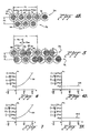
- the variation of aperture pattern of the horizontal direction according to the invention can best be understood by reference first to the ideal grouping of beam landings in relation to associated phosphor deposits at the center 17 of the faceplate, where x and y are both equal to 0.
- This ideal grouping is depicted by figures 4 and 4A--the beam landing areas are indicated as being perfect with relation to the associated phosphor deposits; that is, perfect in concentricity.
- the pattern shown by figures 4, 4A, 5 and 8 represents a positive guard band relationship between the phosphor deposites and the beam landing areas.
- This relationship is indicated in figures 4 and 4A by beam landing area 60, wherein the underlying phosphor deposit 61 is shown diagrammatically as emitting green light under the impact of the electrons.
- the area 63 between the boundaries of the beam landing area 60 and the phosphor deposit 61 comprises the guard band, noted as being a positive guard band for purposes of illustration.
- the other beam landing areas depicted are also concentric with the associated phosphor deposits, indicated diagrammatically as being red-light-emitting and blue-light-emitting.
- the invention has been, and is preferably practiced, in a negative guard band execution (due to the increased brightness and contrast which results). It is herein illustrated in a positive guard band execution because of the considerably greater ease in depicting (and understanding) the invention in its positive guard band execution.
- Such a positive guard band execution is shown by figure 4 wherein a section of faceplate 16 is shown as having on its inner surface; that is, the surface facing the shadow mask 36, a row of phosphor deposits 56.
- Phosphor deposits 61, 62 and 64 are indicated graphically as emitting green, blue and red light, respectively, under the impact of three electron beamlets 66.
- the beamlets 66 are depicted as having passed through an aperture 68 in tensed foil shadow mask 36. (The origin of the beamlets; that is, the electron beams 40, 42 and 44 emitted by the electron gun 38 depicted in figure 1, is not depicted in this figure 4.)
- the beamlets 66 will be noted as being in line in accord with the beam emission of the in-line electron gun 38.
- phosphor deposits in the same row 56 which are a part of adjacent trios of phosphor deposits, comprise green-light-emitting deposit 72, blue-light-emitting deposit 74, and a red-light-emitting deposit next in sequent (not shown) which are activated by beamlets passing through adjacent aperture 69.
- the horizontal pitch Pho of mask 36, and the vertical pitch Pvo of mask 36, are noted by the respective arrows.
- Another row 76 of phosphor deposits is shown as being located beneath row 56. Only two of the deposits are shown: phosphor deposit 78, depicted as emitting red light, and deposit 80, depicted as emitting green light.
- the third member of the trio--a blue-light-emitting deposit-- is not shown.
- the phosphors of the trio are activated by beamlets (not shown) emerging from aperture 82.
- Figure 4A is a plan view of the two rows 56 and 76 of the phosphor deposits on faceplate 16 shown by figure 4.
- P1 is the horizontal pitch of the phosphor deposits of common color emission, indicated by way of example as being green-light-emitting phosphor deposits 61 and 72.
- Pitch P1/3 is indicated as being the spacing between the centers of adjacent phosphor deposits 61, 62, 64 and 72.
- P4 is indicated as representing the pitch of the rows of phosphor deposits in a vertical direction.
- the beam landings indicated diagrammatically in figures 4 and 4A by the shaded areas, will be noted as being concentric with the respective phosphor deposit; this is a condition achieved only at the center of the screen. However, with a mask having a uniform hexagonal array of apertures with constant horizontal aperture pitch, the perfect beam landings achieved at the screen center are not achieved away from the center.
- the horizontal degrouping error grows parabolically with the horizontal and vertical screen position.
- the effect of the resultant degrouping away from the screen center in a horizontal direction is indicated by figure 5 for a mask not having a grouping of apertures according to the invention.
- Beam landing area 86 of blue-light-emitting phosphor deposit 88, energized by a "blue" beamlet is depicted in close adjacency to beam landing area 89 of red-light-emitting phosphor deposit 90, energized by a "red” beamlet.
- the respective guard bands 92 and 94 will be seen as being overcome to the point where color impurities and color shading can occur.
- the horizontal degrouping error (Phe) can be expressed as P2 - P1/3.
- Constants "a” and “b” are functions of the tube size, screen aspect ration, beam deflections angles, and the characteristics of the gun and yoke, which are an in-line gun and self-converging yoke.
- Figures 6 and 7 depict respectively the parabolic growth of the horizontal degrouping error with vertical and horizontal screen position.
- the y axis represents the horizontal pitch at the degrouped beam landing areas as a function of the distance from the center of the screen, where Pho is the horizontal pitch of the beam landing areas (and phosphor deposits) in the screen center.
- the constant "b" is 0.06
- the horizontal pitch of the beam landing areas at the top of the screen is 1+0.06, or 1.06 times the horizontal pitch Pho at the screen center.
- the constant "a” may be 0.08, by way of example.
- the horizontal pitch of the degrouped beam landing areas as a function distance from faceplate is 1+0.08, or 1.08 times Pho.
- the horizontal pitch, P6, of the mask apertures away from the mask center is changed according to the invention from a constant pitch P1 at mask center (see figure 4A) in such a way that the horizontal degrouping error at any point on the screen away from the mask center equals zero at all screen positions.
- the horizontal spacing between adjacent phosphor deposits is equal to one-third of P6 at this or any other mask position away from the center.
- the vertical pitch, P4 of the mask apertures according to the invention remains constant throughout the mask.
- the mask apertures according to the invention are characterized by having a variable horizontal pitch and a uniform, or constant, vertical pitch.
- FIG 9 represents the upper right quadrant of shadow mask 36 according to the invention.
- the horizontal pitch of the apertures increases outwardly according to the invention from mask center 106 according to a function which is parabolic with horizontal displacement.
- the pitch Pho adjacent to the mask center 106 is depicted as increasing to 1.06 Pho at 108--the 12 o'clock edge position of the mask.
- At 110--the three o'clock edge position on the mask--the distance between aperture centers is 1.08 Pho
- at 112--the top right corner of the mask--the distance between aperture centers is 1.14 Pho.
- the horizontal pitch of the apertures is isotropic in the sense that the increase in pitch is the sum of the horizontal displacement contribution and the vertical displacement contribution.
- the top right corner 112 has a horizontal pitch increase equal to the sum of the 3 o'clock increase plus the 12 o'clock increase.
- the mask apertures become increasingly separated horizontally, but are constant in vertical separation according to the invention.
- the mask apertures again become increasingly separated horizontally, but are constant in vertical spacing.
- the rate of increase is parabolic, but the parabolic functions are somewhat different, as described above.
- the increasing horizontal spacing of the mask apertures represents a sum of each of the aforesaid components.
- the apertures define a locus of points identified by curved line 114 that indicates a pincushion distortion in the horizontal direction, but no significant distortion in the vertical direction.
- variable horizontal pitch increases outwardly from the mask center 106 according to the relation where, as noted, the coefficients a and b are determined by such factors as the tube size, screen aspect ratio, beam deflection angles, and the characteristics of the gun and yoke, noted as being the in-line gun and the self-converging yoke; H and W are the height and width of the mask array; x and y are the horizontal and vertical locations at a point on the mask array; and Pho is the pitch of the mask in the horizontal direction at the screen center.
- the coefficients a and b are both in the range of from 0.02 to 0.30 according to a preferred form of the invention.
Landscapes
- Electrodes For Cathode-Ray Tubes (AREA)
Claims (7)

Applications Claiming Priority (2)
| Application Number | Priority Date | Filing Date | Title |
|---|---|---|---|
| US06/843,890 US4794299A (en) | 1986-03-25 | 1986-03-25 | Flat tension mask color CRT front assembly with improved mask for degrouping error compensation |
| US843890 | 1986-03-25 |
Publications (3)
| Publication Number | Publication Date |
|---|---|
| EP0239083A2 EP0239083A2 (de) | 1987-09-30 |
| EP0239083A3 EP0239083A3 (en) | 1988-01-13 |
| EP0239083B1 true EP0239083B1 (de) | 1991-01-16 |
Family
ID=25291261
Family Applications (1)
| Application Number | Title | Priority Date | Filing Date |
|---|---|---|---|
| EP87104353A Expired - Lifetime EP0239083B1 (de) | 1986-03-25 | 1987-03-24 | Flache Lochmaske für eine Farbbildröhre |
Country Status (11)
| Country | Link |
|---|---|
| US (1) | US4794299A (de) |
| EP (1) | EP0239083B1 (de) |
| JP (1) | JPS63942A (de) |
| KR (1) | KR920009825B1 (de) |
| BR (1) | BR8701342A (de) |
| CA (1) | CA1274270A (de) |
| DE (1) | DE3767335D1 (de) |
| FI (1) | FI91572C (de) |
| HK (1) | HK64391A (de) |
| MX (1) | MX167525B (de) |
| SG (1) | SG63291G (de) |
Families Citing this family (17)
| Publication number | Priority date | Publication date | Assignee | Title |
|---|---|---|---|---|
| US4972117A (en) * | 1989-01-17 | 1990-11-20 | Zenith Electronics Corporation | Sparkle suppression displays |
| US5039907A (en) * | 1989-01-17 | 1991-08-13 | Zenith Electronics Corporation | Sparkle-free color display |
| JPH02250239A (ja) * | 1989-03-23 | 1990-10-08 | Tohoku Gakuin Univ | 陰極線管 |
| JPH06275206A (ja) * | 1993-03-19 | 1994-09-30 | Hitachi Ltd | 可変孔ピッチのシャドウマスクを備えたカラー陰極線管 |
| JP3894962B2 (ja) * | 1994-04-12 | 2007-03-22 | 株式会社東芝 | カラー受像管 |
| JP2993437B2 (ja) * | 1996-08-23 | 1999-12-20 | ソニー株式会社 | カラー受像管用ガラスバルブ及びカラー受像管 |
| KR100545712B1 (ko) * | 1998-06-29 | 2006-05-23 | 엘지전자 주식회사 | 칼라음극선관용 섀도우마스크 |
| KR100357948B1 (ko) | 1999-11-10 | 2002-10-25 | 삼성에스디아이 주식회사 | 평면형 칼러 음극선관 |
| KR100388903B1 (ko) | 1999-12-10 | 2003-06-25 | 삼성에스디아이 주식회사 | 평면형 음극선관용 섀도우마스크 프레임 조립체 |
| KR100683647B1 (ko) | 2000-04-21 | 2007-02-15 | 삼성에스디아이 주식회사 | 칼라 음극선관의 텐션 마스크 프레임 조립체 |
| JP2001357794A (ja) * | 2000-06-12 | 2001-12-26 | Hitachi Ltd | カラー受像管 |
| KR20040041578A (ko) | 2001-08-23 | 2004-05-17 | 코닌클리케 필립스 일렉트로닉스 엔.브이. | 개선된 섀도우 마스크를 가진 컬러 디스플레이 튜브 |
| US6861792B2 (en) * | 2002-03-29 | 2005-03-01 | Sony Corporation | Color separator for emissive display |
| US6777861B2 (en) * | 2002-03-29 | 2004-08-17 | Sony Corporation | Color selector for emissive image display apparatus |
| US20030184531A1 (en) * | 2002-03-29 | 2003-10-02 | Sony Corporation | GLV engine for image display |
| US6947198B2 (en) * | 2002-03-29 | 2005-09-20 | Sony Corporation | Emissive image display apparatus |
| US6788354B2 (en) | 2002-04-01 | 2004-09-07 | Sony Corporation | Method for making color separator for emissive display |
Citations (1)
| Publication number | Priority date | Publication date | Assignee | Title |
|---|---|---|---|---|
| JPS59165338A (ja) * | 1983-03-10 | 1984-09-18 | Toshiba Corp | カラ−受像管 |
Family Cites Families (11)
| Publication number | Priority date | Publication date | Assignee | Title |
|---|---|---|---|---|
| US2755402A (en) * | 1953-09-28 | 1956-07-17 | Rca Corp | Color kinescopes of the masked-target dot-screen variety |
| US2947899A (en) * | 1958-01-23 | 1960-08-02 | Zenith Radio Corp | Color image reproducers |
| GB1165766A (en) * | 1967-06-06 | 1969-10-01 | Thorn Aei Radio And Tubes Ltd | Improvements in Cathode Ray Tubes for Colour Television |
| US3652895A (en) * | 1969-05-23 | 1972-03-28 | Tokyo Shibaura Electric Co | Shadow-mask having graduated rectangular apertures |
| JPS4831372B1 (de) * | 1969-05-31 | 1973-09-28 | ||
| NL7303077A (de) * | 1973-03-06 | 1974-09-10 | ||
| US4370591A (en) * | 1979-09-14 | 1983-01-25 | Hitachi, Ltd. | Color picture tube shadow mask |
| JPS5723446A (en) * | 1980-07-18 | 1982-02-06 | Toshiba Corp | Shadow mask for color picture tube |
| JPS58157039A (ja) * | 1982-03-12 | 1983-09-19 | Mitsubishi Electric Corp | シヤドウマスク式カラ−陰極線管 |
| JPS5999505A (ja) * | 1982-11-29 | 1984-06-08 | Mitsubishi Electric Corp | 電子ミシンの制御装置 |
| EP0121628A1 (de) * | 1983-03-03 | 1984-10-17 | Tektronix, Inc. | Kathodenstrahlröhre mit Straffschattenmaske |
-
1986
- 1986-03-25 US US06/843,890 patent/US4794299A/en not_active Expired - Lifetime
-
1987
- 1987-03-17 CA CA000532197A patent/CA1274270A/en not_active Expired - Fee Related
- 1987-03-24 MX MX005679A patent/MX167525B/es unknown
- 1987-03-24 FI FI871290A patent/FI91572C/fi not_active IP Right Cessation
- 1987-03-24 EP EP87104353A patent/EP0239083B1/de not_active Expired - Lifetime
- 1987-03-24 BR BR8701342A patent/BR8701342A/pt not_active IP Right Cessation
- 1987-03-24 DE DE8787104353T patent/DE3767335D1/de not_active Expired - Fee Related
- 1987-03-25 JP JP62071308A patent/JPS63942A/ja active Pending
- 1987-03-25 KR KR1019870002722A patent/KR920009825B1/ko not_active Expired
-
1991
- 1991-08-01 SG SG632/91A patent/SG63291G/en unknown
- 1991-08-15 HK HK643/91A patent/HK64391A/en not_active IP Right Cessation
Patent Citations (1)
| Publication number | Priority date | Publication date | Assignee | Title |
|---|---|---|---|---|
| JPS59165338A (ja) * | 1983-03-10 | 1984-09-18 | Toshiba Corp | カラ−受像管 |
Also Published As
| Publication number | Publication date |
|---|---|
| DE3767335D1 (de) | 1991-02-21 |
| FI871290A0 (fi) | 1987-03-24 |
| KR870009437A (ko) | 1987-10-26 |
| CA1274270A (en) | 1990-09-18 |
| HK64391A (en) | 1991-08-23 |
| MX167525B (es) | 1993-03-29 |
| EP0239083A2 (de) | 1987-09-30 |
| EP0239083A3 (en) | 1988-01-13 |
| JPS63942A (ja) | 1988-01-05 |
| FI91572B (fi) | 1994-03-31 |
| US4794299A (en) | 1988-12-27 |
| BR8701342A (pt) | 1987-12-29 |
| KR920009825B1 (ko) | 1992-10-22 |
| FI91572C (fi) | 1994-07-11 |
| FI871290A7 (fi) | 1987-09-26 |
| SG63291G (en) | 1991-08-23 |
Similar Documents
| Publication | Publication Date | Title |
|---|---|---|
| EP0239083B1 (de) | Flache Lochmaske für eine Farbbildröhre | |
| US3766419A (en) | Cathode-ray tube with shadow mask having random web distribution | |
| GB2140968A (en) | Cathode-ray tube having an improved screen grid electrode of an inline electron gun | |
| EP0321202A1 (de) | Kathodenstrahlröhre vom Schattenmaskentyp | |
| US6124668A (en) | Color cathode ray tube | |
| EP0168047B1 (de) | Farbbildgerät | |
| EP0325207B1 (de) | Farbbildröhre | |
| US5029256A (en) | Color cathode ray tube | |
| JP2588513B2 (ja) | カラ−陰極線管 | |
| US4751425A (en) | Color display tube with line screen having reduced moire | |
| US4877993A (en) | Inline type color picture tube having coma distortion correcting mechanism | |
| EP0203765B1 (de) | Farbbildröhre | |
| US4701665A (en) | Color cathode-ray tube | |
| US4109177A (en) | Cathode-ray tube having apertured mask | |
| US4983995A (en) | Exposure device for forming phosphor deposited screen in in-line cathode ray tube | |
| CN88101395A (zh) | 彩色阴极射线管装置 | |
| US4370591A (en) | Color picture tube shadow mask | |
| EP0257639B1 (de) | In-line-Farbbildröhre mit einer Komakorrektur | |
| EP0249970A2 (de) | Schattenmaske für eine Farbbildröhre, ihre Aufhängung und Verfahren zur Herstellung des Schirmes einer Farbbildröhre | |
| US7019451B2 (en) | Shadow mask of color CRT | |
| US3835347A (en) | Colour picture tube with improved color purity | |
| KR100596233B1 (ko) | 컬러 음극선관 | |
| GB1578491A (en) | Television display tube | |
| JPH06310049A (ja) | カラー受像管 | |
| JPH02139829A (ja) | カラー受像管 |
Legal Events
| Date | Code | Title | Description |
|---|---|---|---|
| PUAI | Public reference made under article 153(3) epc to a published international application that has entered the european phase |
Free format text: ORIGINAL CODE: 0009012 |
|
| AK | Designated contracting states |
Kind code of ref document: A2 Designated state(s): BE DE FR GB IT NL |
|
| PUAL | Search report despatched |
Free format text: ORIGINAL CODE: 0009013 |
|
| AK | Designated contracting states |
Kind code of ref document: A3 Designated state(s): BE DE FR GB IT NL |
|
| 17P | Request for examination filed |
Effective date: 19880331 |
|
| 17Q | First examination report despatched |
Effective date: 19880801 |
|
| GRAA | (expected) grant |
Free format text: ORIGINAL CODE: 0009210 |
|
| AK | Designated contracting states |
Kind code of ref document: B1 Designated state(s): BE DE FR GB IT NL |
|
| REF | Corresponds to: |
Ref document number: 3767335 Country of ref document: DE Date of ref document: 19910221 |
|
| ITF | It: translation for a ep patent filed | ||
| ET | Fr: translation filed | ||
| PLBE | No opposition filed within time limit |
Free format text: ORIGINAL CODE: 0009261 |
|
| STAA | Information on the status of an ep patent application or granted ep patent |
Free format text: STATUS: NO OPPOSITION FILED WITHIN TIME LIMIT |
|
| 26N | No opposition filed | ||
| REG | Reference to a national code |
Ref country code: GB Ref legal event code: IF02 |
|
| PGFP | Annual fee paid to national office [announced via postgrant information from national office to epo] |
Ref country code: FR Payment date: 20020226 Year of fee payment: 16 Ref country code: DE Payment date: 20020226 Year of fee payment: 16 |
|
| PGFP | Annual fee paid to national office [announced via postgrant information from national office to epo] |
Ref country code: GB Payment date: 20020301 Year of fee payment: 16 |
|
| PGFP | Annual fee paid to national office [announced via postgrant information from national office to epo] |
Ref country code: NL Payment date: 20020311 Year of fee payment: 16 |
|
| PGFP | Annual fee paid to national office [announced via postgrant information from national office to epo] |
Ref country code: BE Payment date: 20020321 Year of fee payment: 16 |
|
| PG25 | Lapsed in a contracting state [announced via postgrant information from national office to epo] |
Ref country code: GB Free format text: LAPSE BECAUSE OF NON-PAYMENT OF DUE FEES Effective date: 20030324 |
|
| PG25 | Lapsed in a contracting state [announced via postgrant information from national office to epo] |
Ref country code: BE Free format text: LAPSE BECAUSE OF NON-PAYMENT OF DUE FEES Effective date: 20030331 |
|
| BERE | Be: lapsed |
Owner name: *ZENITH ELECTRONICS CORP. Effective date: 20030331 |
|
| PG25 | Lapsed in a contracting state [announced via postgrant information from national office to epo] |
Ref country code: NL Free format text: LAPSE BECAUSE OF NON-PAYMENT OF DUE FEES Effective date: 20031001 Ref country code: DE Free format text: LAPSE BECAUSE OF NON-PAYMENT OF DUE FEES Effective date: 20031001 |
|
| GBPC | Gb: european patent ceased through non-payment of renewal fee |
Effective date: 20030324 |
|
| PG25 | Lapsed in a contracting state [announced via postgrant information from national office to epo] |
Ref country code: FR Free format text: LAPSE BECAUSE OF NON-PAYMENT OF DUE FEES Effective date: 20031127 |
|
| NLV4 | Nl: lapsed or anulled due to non-payment of the annual fee |
Effective date: 20031001 |
|
| REG | Reference to a national code |
Ref country code: FR Ref legal event code: ST |
|
| PG25 | Lapsed in a contracting state [announced via postgrant information from national office to epo] |
Ref country code: IT Free format text: LAPSE BECAUSE OF NON-PAYMENT OF DUE FEES;WARNING: LAPSES OF ITALIAN PATENTS WITH EFFECTIVE DATE BEFORE 2007 MAY HAVE OCCURRED AT ANY TIME BEFORE 2007. THE CORRECT EFFECTIVE DATE MAY BE DIFFERENT FROM THE ONE RECORDED. Effective date: 20050324 |