EP0238742B1 - Suction accumulator - Google Patents
Suction accumulator Download PDFInfo
- Publication number
- EP0238742B1 EP0238742B1 EP86305491A EP86305491A EP0238742B1 EP 0238742 B1 EP0238742 B1 EP 0238742B1 EP 86305491 A EP86305491 A EP 86305491A EP 86305491 A EP86305491 A EP 86305491A EP 0238742 B1 EP0238742 B1 EP 0238742B1
- Authority
- EP
- European Patent Office
- Prior art keywords
- conduit
- fluid passageway
- vessel
- suction accumulator
- liquid storage
- Prior art date
- Legal status (The legal status is an assumption and is not a legal conclusion. Google has not performed a legal analysis and makes no representation as to the accuracy of the status listed.)
- Expired
Links
Images


Classifications
-
- F—MECHANICAL ENGINEERING; LIGHTING; HEATING; WEAPONS; BLASTING
- F25—REFRIGERATION OR COOLING; COMBINED HEATING AND REFRIGERATION SYSTEMS; HEAT PUMP SYSTEMS; MANUFACTURE OR STORAGE OF ICE; LIQUEFACTION SOLIDIFICATION OF GASES
- F25B—REFRIGERATION MACHINES, PLANTS OR SYSTEMS; COMBINED HEATING AND REFRIGERATION SYSTEMS; HEAT PUMP SYSTEMS
- F25B43/00—Arrangements for separating or purifying gases or liquids; Arrangements for vaporising the residuum of liquid refrigerant, e.g. by heat
- F25B43/006—Accumulators
-
- F—MECHANICAL ENGINEERING; LIGHTING; HEATING; WEAPONS; BLASTING
- F25—REFRIGERATION OR COOLING; COMBINED HEATING AND REFRIGERATION SYSTEMS; HEAT PUMP SYSTEMS; MANUFACTURE OR STORAGE OF ICE; LIQUEFACTION SOLIDIFICATION OF GASES
- F25B—REFRIGERATION MACHINES, PLANTS OR SYSTEMS; COMBINED HEATING AND REFRIGERATION SYSTEMS; HEAT PUMP SYSTEMS
- F25B2400/00—Component parts or details not otherwise provided for in this subclass
- F25B2400/03—Suction accumulators with deflectors
Definitions
- the present invention relates to a suction accumulator for a refrigeration system for separating liquid refrigerant from gaseous refrigerant, for storing the liquid refrigerant and for providing a metered supply of liquid refrigerant to the suction line of a compressor. More specifically, the present invention relates to an improvement in suction accumulators wherein the efficiency of the suction accumulator is increased and the size of the suction accumulator is reduced for a given mass flow rate of refrigerant as compared to prior art suction accumulators. Furthermore, a suction accumulator is provided which is more economical to manufacture than prior art suction accumulators.
- Closed loop refrigeration systems conventionally employ a refrigerant which is normally in the gaseous state wherein it may be compressed by means of a compressor.
- the refrigerant leaves the compressor at relatively high pressure and is then routed through a condenser coil and an evaporator coil back to the compressor for recompression.
- the refrigerant after it leaves the evaporator, under some circumstances such as startup of the refrigeration system, may be in its liquid state. Also, during certain operating conditions of the refrigeration system, the evaporator will be flooded and excess liquid refrigerant could enter the suction line and return to the compressor. If liquid refrigerant enters the compressor suction inlet, "slugging" of the compressor may result whereby abnormally high pressures are generated in the compressor which in turn could cause blown gaskets, broken valves, etc.
- suction accumulators which act as storage reservoirs for liquid refrigerant which may be present in the suction line to prevent such liquid refrigerant from entering the compressor.
- Such accumulators permit the liquid refrigerant to change to its gaseous state before entering the compressor.
- a commonly used type of suction accumulator (US-A-4 270 934) consists of a liquid storage vessel in which is received a generally U-shaped tube, one end of which is connected to the outlet of the storage vessel and the other end of which is open to the interior of the vessel.
- Such suction accumulators may also include an orifice located in a bottom portion of the U-shaped tube whereby a small controlled amount of liquid refrigerant is metered into the stream of gaseous refrigerant which flows through the U-shaped tube.
- Such accumulators may furthermore provide for pressure equalization whereby the pressure at the outlet of the suction accumulator is equalized with the pressure in the liquid storage vessel to prevent higher pressures in the liquid from forcing liquid refrigerant into the suction inlet of the compressor when the compressor is turned off.
- suction accumulators A problem with such prior art suction accumulators has been the difficulty in providing a small and compact suction accumulator having a large refrigerant mass flow rate. It is important to provide small suction accumulators, particularly in certain refrigeration systems wherein space is at a premium. Furthermore, it is important that suction accumulators be provided at a reasonable cost. Prior art suction accumulators have generally been made of steel, copper or aluminium parts which are assembled by soldering or brazing and which are therefore expensive both in terms of the cost of materials and labour.
- US-A-4 182 136 discloses a suction accumulator of relatively small size wherein the above- mentioned U-shaped tubes have been integrated into a single conduit including a divider weir or plate to divide the single conduit into two fluid flow passages. The structure is also provided with a metering orifice immersed in the liquid refrigerant. While these types of accumulators represent an improvement over the prior art U-shaped tube type of accumulators, these accumulators have not been as effective as desired in providing a high mass refrigerant flow rate while providing an economical and compact design.
- This invention provides a suction accumulator comprising: a storage vessel including a casing having an end wall and defining a liquid storage volume; an inlet for said vessel; a first conduit disposed in said vessel in an, in use, generally vertical orientation; said conduit having an upper first and a lower second end, said conduit including a divider means for forming first and second fluid passageways in said conduit, said first fluid passageway being open to said vessel at said conduit first end; and an outlet for said vessel connected to said second fluid passageway at said conduit first end; wherein a transition member is secured to said conduit second end and forming a third fluid passageway, said third fluid passageway interconnecting said first fluid passageway and said second fluid passageway; and wherein a second conduit extends from said liquid storage volume into said second fluid passageway such that the effective cross-sectional flow area of the lower open end of said second fluid passageway is reduced.
- said transition member may include a spacer means for spacing said transition member from said first end wall.
- said spacer means may comprise an annulus, said annulus forming a chamber. with said first end wall and said transition member, said annulus including apertures therein for fluid flow communication of said liquid storage volume with said chamber.
- a screen may be included in said spacer means between said liquid storage volume and the inlet to said second conduit.
- a tubular support member may be provided for supporting said transition member on said end wall, said tubular support member including apertures therein for fluid flow communication of said liquid storage volume with the volume enclosed in said tubular support member; and a screen may be provided supported in said tubular support member and located in the flow path between said support member apertures and the inlet of said second conduit.
- said screen may include a locating means for locating said screen in said tubular support member.
- transition member, said second conduit, and said spacer means may be formed as a unitary member.
- said unitary member may comprise a moulded plastic member.
- said end wall may include an inwardly protruding tapered portion for locating said spacer means.
- said first conduit may include a pressure equalising passage for equalising the pressures between said second fluid passageway and said liquid storage volume.
- the effective cross-sectional area of the open end of said second fluid passageway at said conduit second end may comprise a fraction in the range of 60 % to 82 % of the actual cross-sectional area of said open end.
- the suction accumulator according to the invention may be relatively small in size compared with prior art accumulators and yet accommodates a high refrigerant mass flow rate and provides an improved liquid refrigerant metering structure.
- a further advantage of the suction accumulator according to the present invention is that it is economical to construct since several of the accumulator parts may be moulded or extruded from a plastic material. More particularly, the transition cap member, the support for the transition cap member, and the liquid metering tube may all be moulded as a single unitary plastic mamber. Furthermore, the conduit may be an extruded plastic member.
- a still further advantage of the suction accumulator according to the present invention is the provision of a very effective and simple pressure equalisation structure.
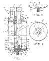
- a suction accumulator 10 including a tubular casing or shell 12.
- the shell may be either cylindrical, as shown, or some other suitable shape.
- Shell 12 includes a top end wall 14 and a bottom end wall 16 to form a vessel 15 for storing liquid refrigerant.
- An inlet 18 and an outlet 20 for the vessel are also provided.
- Inlet 18 is in communication with an inlet opening 22 in top end wall 14.
- Outlet 20 is inserted through an outlet opening 24 in top end wall 14.
- the inlet and outlet each comprise copper or aluminum tubes which are secured to top end wall 14 by soldering, brazing or the like.
- baffle 26 is shown mounted in an upper portion of the vessel whereby refrigerant which enters inlet 18, as shown by means of the arrow 19 indicating the direction of flow, strikes baffle 26 and is deflected.
- liquid refrigerant entering inlet 18 collects in the bottom of vessel 15 and gaseous refrigerant flows to outlet 20 by way of a flow path through accumulator 10 as further explained hereinbelow.
- Baffle 26 may be formed from either a plastic or a metal material. The construction and method of operation of baffle 26 are further described in US-A-4 651 540 to which reference should be made.
- Bottom end wall 16 is provided with a mounting stud 28 to mount the suction accumulator in a vertical position in a refrigeration system as is conventional.
- Mounting stud 28 is provided with a welding pad 29 for securing the mounting stud to a protruding portion 30 of end wall 16 which extends inwardly and upwardly into vessel 15.
- Protruding end wall portion 30 also includes a tapered portion 31 for purposes further explained hereinafter.
- conduit 32 is disposed inside vessel 15.
- the conduit includes a divider plate or weir 34 to firm two fluid flow passages 36, and 38 in conduit 32.
- Conduit 32 may be made of extruded plastic material such as ULTEM 1000 manufactured by the General Electric co. of Mt. Vernon, Indiana.
- conduit 32 may also be made of metal such as for instance by extrusion from aluminium.
- a transition cap member 44 is sealingly secured to a lower end portion of conduit 32. Cap member may be sealed to conduit 32 by an interference fit, plastic welding, an adhesive, or the like. Transition cap 44 is shown in further detail in Figs. 3, 4, and 5.
- Transition cap 44 includes an upstanding annular wall 46 and a bottom wall 50 to form a cup 47 including an enclosed cup volume 48. Transition cap 44 also includes a spacer portion 52 for spacing the cup 47 from bottom end wall 16 of vessel 15. As best seen in Figs. 1 and 5, spacer 52 is cylindrical in configuration and engages with tapered portion 31 of bottom end wall 16. Thus, the upper end of conduit 32 is secured, such as by a press fit, with outlet 20 which, in turn, is soldered or brazed to upper end wall 14. At its lower end, conduit 32 rests on a shoulder 65 formed by a wall portion 64 of transition cap 44 and thereby forces transition cap 44 into contact with tapered portion 31 of the inwardly protruding portion 30 of bottom end wall 16. Thus, conduit 32 is secured against movement in vessel 15.
- a spacer 52 forms a chamber 56 with bottom wall 50 of transition cap 44 and with protruding portion 30 of bottom end wall 16.
- Cylindrical spacer 52 also includes a pair of apertures 66.
- chamber 56 communicates with the liquid storage volume of vessel 15 by means of apertures 66.
- a tubular conduit 54 extends upwardly from bottom portion 50 of transition cap 44.
- An orifice 60 is provided in the top portion of tubular conduit 54.
- the upper end of tubular conduit 54 extends into the upflow passage 38.
- liquid refrigerant may flow from the liquid storage volume of vessel 15, through aperture 66 and chamber 56, through tubular conduit 54 and orifice 60 into upflow passage 38.
- Transition cap 44 may be made by molding from a plastic material such as, for instance, ULTEM 2300 manufactured by General Electric co. of Mt. Vernon, Indiana. Cap 44, cup 47, spacer 52 and tubular conduit 54 may be integrally molded, thus reducing assembly costs.
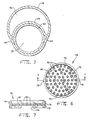
- a screen member 58 including an annular wall portion 72 is located between apertures 66 and the inlet to tubular conduit 54.
- Annular member 72 includes apertures 74 which, in the assembled position of screen member 58, are aligned with apertures 66 in spacer 52.
- a pair of locating ribs 76 on annular wall 72 engage with locating guides 78 in spacer 52 to locate the screen and to align apertures 74 with apertures 66.
- Screen member 58 includes a screen 80 which has screen apertures 82 therein Screen 80 prevents impurities which may be present in the liquid refrigerant in storage vessel 15 from entering tubular conduit 54 and thereby prevents impurities from reaching upflow conduit 38 and the suction inlet of the compressor.
- Screen member 58 may be made by molding from a plastic material such as, for instance, ULTEM 2300 manufactured by the General Electric co. of Mt. Vernon, Indiana.
- a pair of pressure equalizing passages are formed.
- Ducts 84 are formed integrally with conduit 32 and are abaxial with respect to passages 36 and 38.
- the upper ends of ducts 84 are open to apertures 85 in baffle 26 and therefore to the upper end of vessel 15.
- the lower ends of ducts 84 are open to volume 48 of cup 47 and therefore to the upflow passage 38 of conduit 32. Therefore, when the compressor shuts off and system pressure equalization commences, if the liquid refrigerant level in vessel 15 is above the bottom end of conduit 32, it will quickly seal off passages 36 and 38 by filling cup 47 via the orifice 60.
- ducts 84 Without a pressure equalization passage such as provided by ducts 84, the sealing of passages 36 and 38 in conduit 32 would interrupt the pressure equalization and the pressure differentials would thereby force liquid refrigerant up passage 38 and into the compressor inlet, thus resulting in compressor "slugging" upon startup.
- Ducts 84 must open into the upper end of vessel 15 so that only gas passes through ducts 84 to allow pressure equalization to occur between the compressor and the refrigeration system.
- the liquid seal at the bottom of conduit 32 blocks off normal equalization paths, thus necessitating ducts 84 or some other pressure equalization system. Therefore, the use of ducts 84 permits refrigerant gas to flow from vessel 15 through apertures 85 and ducts 84, into the bottom inlet of conduit 38 and out of outlet 20.
- refrigerant including gaseous and entrained liquid refrigerant, flows through inlet 18 into vessel 15 and is separated by baffle 26 into its gaseous and liquid components.
- the liquid refrigerant will flow to the bottom of storage vessel 15.
- the gaseous refrigerant will flow, as indicated by the arrows 87, from the upper end of storage vessel 15 into downflow passage 36 and from there through a connecting passage formed by volume 48 of transition cap member 44 into upflow passage 38 and out of outlet 20. Since the gaseous refrigerant is caused to change directions from the downflow passage 36 to the upflow passage 38 and turns through 180°, turbulence is created at the inlet opening 86 of upflow passage 38.
- This fluid turbulence reduces the effective fluid flow cross sectional area of inlet opening 86 and thereby generates a reduced pressure zone in accordance with Bernoulli's principle.
- the effective fluid flow cross sectional area of opening 86 is in the range of 60 % to 82 % of the actual cross sectional area of opening 86.
- tubular conduit 54 which extends into opening 86, further reduces the effective cross sectional area of opening 86, thereby further reducing the pressure in the lower portion of upflow passage 38.
- a pressure drop is also experienced by the refrigerant which flows through downflow passage 36. Therefore, the pressure on the liquid refrigerant in storage vessel 15 will be higher than the pressure in opening 86 of upflow passage 38.
- Ducts 84 are therefore provided in conduit 32 whereby the pressure in upflow passage 38 will equalize with the pressure in the upper portion of vessel 15, thug permitting flow of gaseous refrigerant through ducts 84 from the upper portion of vessel 15 to the outlet 20.
- the suction accumulator 10 includes a cylindrical or tubular casing 12, a top end wall 14 and a bottom end wall 16 defining a liquid storage vessel 15. An inlet 18 and an outlet 20 are shown.
- the accumulator may be mounted by means of a stud 28 which is secured to bottom end wall 16 by means of a welding pad 29.
- a baffle 100 is shown mounted in the upper portion of vessel 15 and including an equalizer vent hole 101, a tubular conduit 103, and a cylindrical portion 105.
- Inlet 20 is secured in portion 105 as by a force fit.
- a cylindrical conduit 102 is provided including a generally planar divider wall 104 to divide conduit 102 into a downflow passage 106 and an upflow passage 108.
- Conduit 103 is shaped to fit snugly in upflow passage 108 and may be secured therein with an adhesive.
- Outlet 20 mates with a cylindrical portion 105 of baffle 100.
- Conduit 102 is preferably made of ULTEM 1000 manufactured by the General Electric co. of Mt. Vernon, Indiana.
- Transition cap 110 is shown secured to a bottom portion of conduit 102 as with an adhesive.
- Transition cap 110 is preferably made from ULTEM 2300 manufactured by General Electric co. of Mt. Vernon, Indiana.
- Transition cap 110 includes an upstanding wall member 111 and a bottom wall 130 to define a cup-like transition chamber 124.
- Bottom end wall 16 includes a protruding wall portion 112 having a generally cylindrical upstanding wall portion 114.
- a transition cap member 110 includes a spacer portion 126 which fits over protruding wall portion 112 for defining a chamber 116 when transition cap member is assembled to bottom end wall 16.
- a screen 118 which may be made of metal, is disposed in chamber 116.
- Transition cap member 110 includes a pair of apertures 128 and an additional aperture 129.
- Liquid refrigerant may thus flow through apertures 128 and 129 into chamber 116 and through screen 118, a tubular conduit 120, and an orifice 121 into the lower end of upflow conduit 108, in similar fashion as explained hereinabove in connection with the embodiment of Figs. 1 - 9.
- refrigerant including gaseous and entrained liquid refrigerant, flows through inlet 18 into vessel 15 and is separated by baffle 100 into its gaseous and liquid components.
- the liquid refrigerant will flow to the bottom of storage vessel 15.
- the gaseous refrigerant will flow, as indicated by arrows 87, from the upper end of storage vessel 15 into downflow passage 106 and from there through a connecting passage formed by transition cup volume 124 into upflow passage 108 and out of outlet 20.
- the combined pressure drop experienced by refrigerant flowing through downflow conduit 106 and through opening 136 will cause a pressure differential to exist between the liquid refrigerant stored in storage vessel 15 and opening 136 of upflow passage 108.
- Liquid refrigerant is therefore aspirated or drawn into upflow passage 108 by way of apertures 128 and 129, chamber 116, screen 118, tubular conduit 120, and orifice 122.
- the liquid refrigerant is metered by controlling the size of orifice 122.
- As liquid refrigerant enters upflow passage 108 it will aspirate into a mist which blends with the refrigerant gas as it travels through the upflow passage 108 and into the suction side of the compressor.
- Vent passage 101 is provided in baffle 100 to equalize the pressures in the upper portion of vessel 15 through vent 101 by permitting direct flow from the upper portion of vessel 15 to outlet 20, thereby preventing liquid refrigerant from filling upflow conduit 108 and preventing "slugging" of the compressor upon start up.
Landscapes
- Engineering & Computer Science (AREA)
- Thermal Sciences (AREA)
- Analytical Chemistry (AREA)
- Power Engineering (AREA)
- Physics & Mathematics (AREA)
- Mechanical Engineering (AREA)
- Chemical & Material Sciences (AREA)
- General Engineering & Computer Science (AREA)
- Compressor (AREA)
- Applications Or Details Of Rotary Compressors (AREA)
- Jet Pumps And Other Pumps (AREA)
- Massaging Devices (AREA)
- Compressors, Vaccum Pumps And Other Relevant Systems (AREA)
- Medicines Containing Plant Substances (AREA)
Applications Claiming Priority (2)
| Application Number | Priority Date | Filing Date | Title |
|---|---|---|---|
| US842311 | 1986-03-21 | ||
| US06/842,311 US4627247A (en) | 1986-03-21 | 1986-03-21 | Suction accumulator |
Publications (2)
| Publication Number | Publication Date |
|---|---|
| EP0238742A1 EP0238742A1 (en) | 1987-09-30 |
| EP0238742B1 true EP0238742B1 (en) | 1989-05-31 |
Family
ID=25287033
Family Applications (1)
| Application Number | Title | Priority Date | Filing Date |
|---|---|---|---|
| EP86305491A Expired EP0238742B1 (en) | 1986-03-21 | 1986-07-16 | Suction accumulator |
Country Status (8)
| Country | Link |
|---|---|
| US (1) | US4627247A (https=) |
| EP (1) | EP0238742B1 (https=) |
| JP (1) | JPS62225872A (https=) |
| AU (1) | AU568458B2 (https=) |
| BR (1) | BR8604957A (https=) |
| CA (1) | CA1262828A (https=) |
| DE (1) | DE3663735D1 (https=) |
| NZ (1) | NZ216789A (https=) |
Families Citing this family (23)
| Publication number | Priority date | Publication date | Assignee | Title |
|---|---|---|---|---|
| US4651540A (en) * | 1986-03-21 | 1987-03-24 | Tecumseh Products Company | Suction accumulator including an entrance baffle |
| US4757696A (en) * | 1987-06-17 | 1988-07-19 | Tecumseh Products Company | Suction accumulator having slide valve |
| US4827725A (en) * | 1988-07-05 | 1989-05-09 | Tecumseh Products Company | Suction accumulator with dirt trap |
| US5021125A (en) * | 1989-08-30 | 1991-06-04 | Kamyr, Inc. | Pistonless accumulator |
| US5075967A (en) * | 1990-08-03 | 1991-12-31 | Bottum Edward W | Method of assembing a suction accumulator |
| US5471854A (en) * | 1994-06-16 | 1995-12-05 | Automotive Fluid Systems, Inc. | Accumulator for an air conditioning system |
| US5746065A (en) * | 1996-08-21 | 1998-05-05 | Automotive Fluid Systems, Inc. | Accumulator deflector connection and method |
| AU7111096A (en) * | 1996-09-16 | 1998-04-02 | Robert J. Slais | Accumulator deflector having a plastic bushing |
| US6026655A (en) * | 1997-02-27 | 2000-02-22 | Parker-Hannifin Corporation | Liquid accumulator with inlet tube |
| DE19742230C2 (de) * | 1997-09-25 | 1999-08-05 | Hansa Metallwerke Ag | Akkumulator für eine nach dem "Orifice"-Prinzip arbeitende Klimaanlage, insbesondere Fahrzeugklimaanlage |
| US6062039A (en) * | 1998-01-07 | 2000-05-16 | Parker-Hannifin Corporation | Universal accumulator for automobile air conditioning systems |
| US6223555B1 (en) * | 1999-06-08 | 2001-05-01 | Visteon Global Technologies, Inc. | Accumulator for an air conditioning system |
| CA2297598C (en) | 2000-01-28 | 2003-12-23 | Ki-Sun Jason Ryu | Accumulator for an air-conditioning system |
| DE20004328U1 (de) * | 2000-03-08 | 2000-05-18 | Hansa Metallwerke Ag, 70567 Stuttgart | Akkumulator für eine nach dem Orifice-Prinzip arbeitende Klimaanlage, insbesondere Fahrzeugklimaanlage |
| US6463757B1 (en) | 2001-05-24 | 2002-10-15 | Halla Climate Controls Canada, Inc. | Internal heat exchanger accumulator |
| US6568204B2 (en) * | 2001-10-30 | 2003-05-27 | Automotive Fluid Systems, Inc. | Baffle connection for an accumulator and related method of manufacturing |
| DE10158409C1 (de) * | 2001-11-29 | 2003-04-30 | Hansa Metallwerke Ag | Akkumulator für eine Klimaanlage, insbesondere Fahrzeugklimaanlage |
| US20050081559A1 (en) * | 2003-10-20 | 2005-04-21 | Mcgregor Ian A.N. | Accumulator with pickup tube |
| US7461519B2 (en) | 2005-02-03 | 2008-12-09 | Halla Climate Control Canada, Inc. | Accumulator with deflector |
| KR100784611B1 (ko) * | 2006-08-18 | 2007-12-11 | 주식회사 두원공조 | 냉방장치의 내부열교환기 일체형 기액분리기 |
| US9043243B2 (en) * | 2008-06-02 | 2015-05-26 | Apple Inc. | System and method of generating a media package for ingesting into an on-line downloading application |
| TR201110551T1 (tr) * | 2009-04-23 | 2012-05-21 | E. Phillippe Gary | Soğutma ve klima verimliliğini artırmak için yöntem ve aparat. |
| KR102750535B1 (ko) * | 2019-05-31 | 2025-01-06 | 현대자동차 주식회사 | 차량용 기액 분리장치 |
Family Cites Families (30)
| Publication number | Priority date | Publication date | Assignee | Title |
|---|---|---|---|---|
| US421017A (en) * | 1890-02-11 | Exhaust-head | ||
| US796429A (en) * | 1904-10-12 | 1905-08-08 | Charles E Huxley | Steam-separator. |
| US1746406A (en) * | 1927-07-01 | 1930-02-11 | Irving L Keith | Refrigerating system |
| US1978463A (en) * | 1933-01-28 | 1934-10-30 | Frigidaire Corp | Refrigeration |
| US2402845A (en) * | 1944-11-29 | 1946-06-25 | Universal Oil Prod Co | Multiple stage cyclonic separator |
| US3084523A (en) * | 1962-01-30 | 1963-04-09 | Refrigeration Research | Refrigeration component |
| US3163998A (en) * | 1962-09-06 | 1965-01-05 | Recold Corp | Refrigerant flow control apparatus |
| US3283524A (en) * | 1964-03-17 | 1966-11-08 | Byron John Thomson | Refrigeration system |
| US3370440A (en) * | 1966-01-06 | 1968-02-27 | Ac & R Components Inc | Suction accumulator |
| US3429139A (en) * | 1967-08-01 | 1969-02-25 | Borg Warner | Refrigeration system including accumulator means |
| US3563053A (en) * | 1968-09-16 | 1971-02-16 | Edward W Bottum | Suctiin accumulator |
| US3643465A (en) * | 1968-09-16 | 1972-02-22 | Edward W Bottum | Refrigeration suction accumulator |
| US3698207A (en) * | 1970-11-25 | 1972-10-17 | Mccord Corp | Accumulator |
| US3798921A (en) * | 1973-03-26 | 1974-03-26 | Gen Motors Corp | Air conditioning system with freeze throttling valve |
| US3837177A (en) * | 1973-11-01 | 1974-09-24 | Refrigeration Research | Suction accumulator |
| US3872689A (en) * | 1974-05-02 | 1975-03-25 | Edward W Bottum | Suction accumulator |
| US4009596A (en) * | 1975-07-21 | 1977-03-01 | Tecumseh Products Company | Suction accumulator |
| US4194370A (en) * | 1976-08-13 | 1980-03-25 | Tecumseh Products Company | Accumulator for refrigeration system |
| US4194371A (en) * | 1976-08-13 | 1980-03-25 | Tecumseh Products Company | Refrigeration system with compressor mounted accumulator |
| US4111005A (en) * | 1977-04-07 | 1978-09-05 | General Motors Corporation | Press-on plastic baffle for accumulator-dehydrator |
| US4182136A (en) * | 1977-12-22 | 1980-01-08 | Tecumseh Products Company | Suction accumulator |
| US4270934A (en) * | 1978-06-05 | 1981-06-02 | General Motors Corporation | Universal internal tube accumulator |
| US4199960A (en) * | 1978-10-26 | 1980-04-29 | Parker-Hannifin Corporation | Accumulator for air conditioning systems |
| US4187088A (en) * | 1979-01-18 | 1980-02-05 | Maloney-Crawford Corporation | Down flow centrifugal separator |
| US4208887A (en) * | 1979-01-22 | 1980-06-24 | Tecumseh Products Company | Suction accumulator having heat exchanger |
| US4401447A (en) * | 1979-08-31 | 1983-08-30 | Multiform Desiccants, Inc. | Self-retaining adsorbent bag unit |
| US4276756A (en) * | 1980-07-07 | 1981-07-07 | General Motors Corporation | Liquid accumulator |
| US4291548A (en) * | 1980-07-07 | 1981-09-29 | General Motors Corporation | Liquid accumulator |
| US4354362A (en) * | 1980-11-07 | 1982-10-19 | Virginia Chemicals, Inc. | Integral suction line accumulator/filter-drier |
| US4474035A (en) * | 1983-12-23 | 1984-10-02 | Ford Motor Company | Domed accumulator for automotive air conditioning system |
-
1986
- 1986-03-21 US US06/842,311 patent/US4627247A/en not_active Expired - Lifetime
- 1986-07-08 NZ NZ216789A patent/NZ216789A/xx unknown
- 1986-07-09 CA CA000513409A patent/CA1262828A/en not_active Expired
- 1986-07-16 EP EP86305491A patent/EP0238742B1/en not_active Expired
- 1986-07-16 DE DE8686305491T patent/DE3663735D1/de not_active Expired
- 1986-07-31 AU AU60740/86A patent/AU568458B2/en not_active Ceased
- 1986-09-30 JP JP61230209A patent/JPS62225872A/ja active Granted
- 1986-10-07 BR BR8604957A patent/BR8604957A/pt not_active IP Right Cessation
Also Published As
| Publication number | Publication date |
|---|---|
| US4627247A (en) | 1986-12-09 |
| NZ216789A (en) | 1988-09-29 |
| BR8604957A (pt) | 1987-11-17 |
| EP0238742A1 (en) | 1987-09-30 |
| CA1262828A (en) | 1989-11-14 |
| AU568458B2 (en) | 1987-12-24 |
| DE3663735D1 (en) | 1989-07-06 |
| JPH0454869B2 (https=) | 1992-09-01 |
| AU6074086A (en) | 1987-09-24 |
| JPS62225872A (ja) | 1987-10-03 |
Similar Documents
| Publication | Publication Date | Title |
|---|---|---|
| EP0238742B1 (en) | Suction accumulator | |
| US4651540A (en) | Suction accumulator including an entrance baffle | |
| US4827725A (en) | Suction accumulator with dirt trap | |
| US6158503A (en) | Air conditioning condenser having a fluid tank with interchangeable cartridge | |
| US5787729A (en) | Accumulator deflector | |
| US5289697A (en) | Refrigerant receiver/drier | |
| JPH04103973A (ja) | レシーバタンク一体型コンデンサ | |
| US5076071A (en) | Suction accumulator with dirt trap and filter | |
| CA1297308C (en) | Suction accumulator having slide valve | |
| EP4183466A1 (en) | Gas-liquid separator | |
| US4458505A (en) | Suction line accumulator | |
| CN111578564A (zh) | 一种气液分离装置 | |
| KR20230087585A (ko) | 냉매 어큐뮬레이터 및 냉매용 내부 열교환기의 조합체, 연결 부품, 내부 열교환기 및 어큐뮬레이터 | |
| US6125652A (en) | Apparatus for minimizing refrigerant usage | |
| CN116804502A (zh) | 气液分离装置及热管理系统 | |
| US20250164162A1 (en) | Cold water tank assembly and manufacturing method thereof | |
| EP0666456A1 (en) | Refrigerant receiver/drier | |
| JP2001304725A (ja) | 冷凍システム用レシーバタンク | |
| EP1136772B1 (en) | Air-conditioning refrigerant receiver | |
| CN210602365U (zh) | 气液分离器及压缩机 | |
| CN220380026U (zh) | 气液分离器 | |
| JP2000186871A (ja) | レシ―バタンク一体型コンデンサ | |
| CN113530797A (zh) | 油分离器、压缩机组件及热交换设备 | |
| CN218936737U (zh) | 一种具有新型结构的气液分离器 | |
| CN221117072U (zh) | 一种水汽分离盒及出水龙头 |
Legal Events
| Date | Code | Title | Description |
|---|---|---|---|
| PUAI | Public reference made under article 153(3) epc to a published international application that has entered the european phase |
Free format text: ORIGINAL CODE: 0009012 |
|
| AK | Designated contracting states |
Kind code of ref document: A1 Designated state(s): DE FR GB IT |
|
| 17P | Request for examination filed |
Effective date: 19870918 |
|
| 17Q | First examination report despatched |
Effective date: 19880620 |
|
| GRAA | (expected) grant |
Free format text: ORIGINAL CODE: 0009210 |
|
| AK | Designated contracting states |
Kind code of ref document: B1 Designated state(s): DE FR GB IT |
|
| ITF | It: translation for a ep patent filed | ||
| REF | Corresponds to: |
Ref document number: 3663735 Country of ref document: DE Date of ref document: 19890706 |
|
| ET | Fr: translation filed | ||
| PLBE | No opposition filed within time limit |
Free format text: ORIGINAL CODE: 0009261 |
|
| STAA | Information on the status of an ep patent application or granted ep patent |
Free format text: STATUS: NO OPPOSITION FILED WITHIN TIME LIMIT |
|
| 26N | No opposition filed | ||
| PGFP | Annual fee paid to national office [announced via postgrant information from national office to epo] |
Ref country code: GB Payment date: 19900601 Year of fee payment: 5 |
|
| PG25 | Lapsed in a contracting state [announced via postgrant information from national office to epo] |
Ref country code: GB Effective date: 19910716 |
|
| ITTA | It: last paid annual fee | ||
| PGFP | Annual fee paid to national office [announced via postgrant information from national office to epo] |
Ref country code: DE Payment date: 19910828 Year of fee payment: 6 |
|
| GBPC | Gb: european patent ceased through non-payment of renewal fee | ||
| PG25 | Lapsed in a contracting state [announced via postgrant information from national office to epo] |
Ref country code: DE Effective date: 19930401 |
|
| PGFP | Annual fee paid to national office [announced via postgrant information from national office to epo] |
Ref country code: FR Payment date: 20030609 Year of fee payment: 18 |
|
| PG25 | Lapsed in a contracting state [announced via postgrant information from national office to epo] |
Ref country code: FR Free format text: LAPSE BECAUSE OF NON-PAYMENT OF DUE FEES Effective date: 20050331 |
|
| REG | Reference to a national code |
Ref country code: FR Ref legal event code: ST |
|
| PG25 | Lapsed in a contracting state [announced via postgrant information from national office to epo] |
Ref country code: IT Free format text: LAPSE BECAUSE OF NON-PAYMENT OF DUE FEES;WARNING: LAPSES OF ITALIAN PATENTS WITH EFFECTIVE DATE BEFORE 2007 MAY HAVE OCCURRED AT ANY TIME BEFORE 2007. THE CORRECT EFFECTIVE DATE MAY BE DIFFERENT FROM THE ONE RECORDED. Effective date: 20050716 |