EP0238680A1 - Platelage pour échafaudages - Google Patents
Platelage pour échafaudages Download PDFInfo
- Publication number
- EP0238680A1 EP0238680A1 EP86104001A EP86104001A EP0238680A1 EP 0238680 A1 EP0238680 A1 EP 0238680A1 EP 86104001 A EP86104001 A EP 86104001A EP 86104001 A EP86104001 A EP 86104001A EP 0238680 A1 EP0238680 A1 EP 0238680A1
- Authority
- EP
- European Patent Office
- Prior art keywords
- scaffolding
- planks
- covering according
- end faces
- scaffolds
- Prior art date
- Legal status (The legal status is an assumption and is not a legal conclusion. Google has not performed a legal analysis and makes no representation as to the accuracy of the status listed.)
- Withdrawn
Links
Images

Classifications
-
- E—FIXED CONSTRUCTIONS
- E04—BUILDING
- E04G—SCAFFOLDING; FORMS; SHUTTERING; BUILDING IMPLEMENTS OR AIDS, OR THEIR USE; HANDLING BUILDING MATERIALS ON THE SITE; REPAIRING, BREAKING-UP OR OTHER WORK ON EXISTING BUILDINGS
- E04G1/00—Scaffolds primarily resting on the ground
- E04G1/15—Scaffolds primarily resting on the ground essentially comprising special means for supporting or forming platforms; Platforms
- E04G1/154—Non-detachably fixed and secured connections between platform and scaffold
-
- E—FIXED CONSTRUCTIONS
- E04—BUILDING
- E04G—SCAFFOLDING; FORMS; SHUTTERING; BUILDING IMPLEMENTS OR AIDS, OR THEIR USE; HANDLING BUILDING MATERIALS ON THE SITE; REPAIRING, BREAKING-UP OR OTHER WORK ON EXISTING BUILDINGS
- E04G1/00—Scaffolds primarily resting on the ground
- E04G1/15—Scaffolds primarily resting on the ground essentially comprising special means for supporting or forming platforms; Platforms
- E04G1/152—Platforms made of metal or with metal-supporting frame
-
- E—FIXED CONSTRUCTIONS
- E04—BUILDING
- E04G—SCAFFOLDING; FORMS; SHUTTERING; BUILDING IMPLEMENTS OR AIDS, OR THEIR USE; HANDLING BUILDING MATERIALS ON THE SITE; REPAIRING, BREAKING-UP OR OTHER WORK ON EXISTING BUILDINGS
- E04G7/00—Connections between parts of the scaffold
- E04G7/02—Connections between parts of the scaffold with separate coupling elements
- E04G7/28—Clips or connections for securing boards
-
- E—FIXED CONSTRUCTIONS
- E04—BUILDING
- E04G—SCAFFOLDING; FORMS; SHUTTERING; BUILDING IMPLEMENTS OR AIDS, OR THEIR USE; HANDLING BUILDING MATERIALS ON THE SITE; REPAIRING, BREAKING-UP OR OTHER WORK ON EXISTING BUILDINGS
- E04G1/00—Scaffolds primarily resting on the ground
- E04G1/15—Scaffolds primarily resting on the ground essentially comprising special means for supporting or forming platforms; Platforms
- E04G2001/158—Platforms supported by spigots which engage through holes in the platform
Definitions
- the invention relates to a scaffolding covering for scaffolding, in particular for tubular steel scaffolding, consisting of shear-resistant planks, which have hook-shaped brackets on the end faces for form-fitting support attachment to the crossbars of the scaffolding and are secured against arbitrary lifting off the crossbars.
- Scaffolding coverings form the catwalks and work stands for the people working on the scaffolding and are therefore one of the most important elements of scaffolding. In addition, however, they also have the other important function of longitudinal and transverse stiffening of the entire scaffolding structure. Due to this special importance for the stability of the scaffolding and for the safety of the people working on the scaffolding, there are strict regulations in various countries for the properties of the individual planks as well as for their laying and secure fastening.
- the top Crossbars of each frame are designed in the form of an upwardly open U-profile, in the vertical side legs of which the planks are hung with the hooks on the front.
- the lower crossbars of the next upper scaffold are designed as tubes and are arranged at such a distance that they press against the hooks from above and / or prevent lifting of the hooks upwards.
- scaffolding coverings cannot be used for so-called modular scaffolds that are assembled on site from individual tube stands and tubular crossbars mounted on their support brackets.
- these known scaffolding coverings often give the scaffolding insufficient rigidity in the direction of the crossbars, ie perpendicular to the facade walls.
- the planks have a plurality of cross holes at their front ends.
- the crossbars provided for supporting these planks of the individual frames are designed, for example, as a square profile and have upwardly projecting pegs on both sides, which are arranged and welded to the crossbars so that they engage in the end holes of the planks when laying the planks.
- the prerequisite is the use of crossbars with laterally protruding pegs or a square cross-section to ensure a sufficient contact surface for the planks.
- modular scaffolds are characterized by the fact that they do not consist of individual, inherently rigid frames but of a large number of individual parts which can then be assembled on site in an individual and varied manner.
- the pipe stands used have dimensionally stable, ring-shaped support brackets at predetermined vertical intervals, to which the longitudinal struts and also the crossbars are connected using special fastening elements.
- the advantage of such modular scaffolding is its universal applicability and the diversity of its adaptation to different structures. Under certain circumstances, however, achieving the required rigidity of the scaffold structure can be problematic.
- tubular longitudinal and transverse bars are required for this type of scaffold, the ends of which are fastened to the ring-shaped support brackets of the tubular steel stands by means of suitable wedge connections or the like.
- tubular profiles of the longitudinal and crossbeams are necessary to absorb and transmit the high effective forces without deformation.
- hook-shaped claws are welded to the two end faces of the planks with mutual displacement, the inner contact surface of which is rounded in accordance with the crossbar diameters and which overlap the crossbars.
- the object of the invention is to provide a scaffolding covering which is suitable for frame scaffolding as well as for modular scaffolding without retrofitting and which brings about an effective horizontal stiffening of the scaffolding construction.
- the additional fastening elements consist of U-shaped staples which engage from above in correspondingly positioned holes at the ends of two adjacent planks.
- U-shaped cramps over not only bear the shear and tensile forces effective in the longitudinal direction of the planks from one plank to the other, but can also absorb the "pulling forces" acting outwards transversely to the wall of the building and thus effectively stiffen the entire scaffolding structure.
- the cross struts bearing the downward-facing cramps are expediently designed as flat irons and engage in corresponding depressions on the end edges of the two planks laid one behind the other, so that their surface corresponds approximately to the surface of the planks.
- each plank can have at least one two holes on one end face and two pins on the other end face for engaging in the holes of the next plank.
- the pins are expediently fastened to the underside of tabs which overlap the adjacent edge strips of the adjacent plank.
- the individual planks of the scaffolding covering according to the invention advantageously consist of a perforated steel sheet and have the shape of a box profile in cross-section with inwardly bent lower edge edges.
- the holes for the engagement of the staples or the pins are preferably carried out in horizontal tabs of multi-angled profile parts with lateral tongues. These profile parts are pushed into the box profile of the planks from the front and welded to size.
- the frame structure consists of a lower frame 1 and an upper frame 2.
- Each frame has vertical tubular steel stands 3, 4, which are rigid and non-detachable at their lower end by a cross bar 5 and at their upper end by a tubular cross bar 6, for example by welding.
- the tubular steel stands 3, 4 of the upper frame 2 are attached with their downwardly open ends to vertical longitudinal pins 7, 8, which are attached to the upper end of the two tubular steel stands 3 ⁇ , 4 ⁇ of the lower frame above.
- the upper crossbars 6 of each frame serve as supporting elements for floorboards 10, which in the exemplary embodiment according to FIG. 1 are each laid twice next to one another and form the scaffolding covering.
- a profile element made of, for example, bent steel sheet is welded to the two end faces of each plank 10 and has a tab 11 projecting in the longitudinal direction over the end edge of the actual plank, in which two through transverse holes 12 are formed. The positioning is carried out so that the holes of two planks laid one behind the other are exactly opposite.
- Hook-shaped claws 14 are also welded to the underside of the tabs 11, as are shown, for example, in FIG. 4 and are also used in conventional modular scaffolding. These claws overlap in the Darge in Fig. 4 set the respective cross bar, the claws 14 on one end of the plank 10 with respect to the claws 14 on the other end side are laterally offset from each other by predetermined amounts in order to enable a common overlap of the tubular cross bar 6.
- the individual planks are made of sheet steel, which consists of a box profile with a possibly roughened wing and side walls 15 bent downwards and edge edges 16 bent inwards.
- the formed from multi-angled sheet steel sections 13, which carry the tabs 12 on their end face, are inserted and welded into the open ends of the box sections.
- the protruding tabs 11 form a shoulder to the wing of the box-shaped steel sheet floorboards 10, the height of which corresponds approximately to the wall thickness of the floorboard steel sheet.
- the depression formed by the tabs in relation to the supporting surface of the plank can also be produced in another way.
- the lower cross strut 5 of the upper frame 2 is made of a flat iron and carries on its underside a total of four U-shaped cramps 18, which are aligned in the longitudinal direction of the scaffold covering and are welded to the cross strut 5 at predetermined intervals.
- the position and size of these U-clamps 18 is selected so that they engage in a lowering movement of the upper frame in the pairs of holes 12 of two adjacent tabs 11 on the two mutually facing end faces of boards 10 laid at a distance from one another and in this way the In addition to holding them on the cross struts 6, connect the floorboards to one another in a dimensionally stable manner by means of the hook-shaped claws 14.
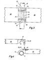
- the scaffolding covering consists of three planks 10 laid next to one another, which are identical to the planks 10 of the embodiment according to FIG. 1.
- These planks 10 are used as scaffolding covering in a so-called modular scaffolding, on the vertical tubular steel stands 23, 24 of which annular support brackets 25 are welded at predetermined intervals.
- These support brackets are used in the usual way for the fixed connection of cross and / or longitudinal bolts with the help of special fastening elements which encompass the collar of the ring brackets and, if necessary, are secured by wedges or pivot levers.
- the crossbars 26 used have a tubular profile and serve as support elements for the floorboards 10, which in the manner shown in FIG. 4 below are overlapped by the hook-shaped claws welded to the end plates 11 of the floorboards.
- the staples 18 are welded to the underside of a cross strut 27, which is designed as an entire component in a flat profile, for example as a flat iron.
- the flat iron 27 is placed over the plank flaps 11 in such a way that the pins of the staples 18 engage in the respective pairs of holes 12. Due to the depression, the surface of the flat profile strut 17 at least approximately closes with the surfaces of the planks, so that the entire sliding surface is given a largely flat walking surface and tripping hazards are avoided.
- the embodiment of the scaffolding covering according to the invention shown in FIGS. 3 and 4 likewise consists of a plurality of planks 30 laid one behind the other and possibly also next to one another, which can consist of shaped steel sheet, wooden planks and / or also of other suitable materials.
- the planks 30 have flat tabs 31, 32 protruding on their two end faces, on the underside of which the hook-shaped claws 14, 15 are welded.
- the invention is not restricted to the exemplary embodiments shown.
- other means for the direct connection at both ends of two planks laid on a scaffold can also be used, which ensure a positive connection in the longitudinal direction of the plank as well as in the transverse direction of the plank.
- box sections made of molded sheet steel is particularly useful for the manufacture of the planks, other planks, e.g. Planks, gratings or the like assembled from wooden boards are used.
Landscapes
- Engineering & Computer Science (AREA)
- Architecture (AREA)
- Mechanical Engineering (AREA)
- Civil Engineering (AREA)
- Structural Engineering (AREA)
- Movable Scaffolding (AREA)
Priority Applications (1)
| Application Number | Priority Date | Filing Date | Title |
|---|---|---|---|
| EP86104001A EP0238680A1 (fr) | 1986-03-24 | 1986-03-24 | Platelage pour échafaudages |
Applications Claiming Priority (1)
| Application Number | Priority Date | Filing Date | Title |
|---|---|---|---|
| EP86104001A EP0238680A1 (fr) | 1986-03-24 | 1986-03-24 | Platelage pour échafaudages |
Publications (1)
| Publication Number | Publication Date |
|---|---|
| EP0238680A1 true EP0238680A1 (fr) | 1987-09-30 |
Family
ID=8194996
Family Applications (1)
| Application Number | Title | Priority Date | Filing Date |
|---|---|---|---|
| EP86104001A Withdrawn EP0238680A1 (fr) | 1986-03-24 | 1986-03-24 | Platelage pour échafaudages |
Country Status (1)
| Country | Link |
|---|---|
| EP (1) | EP0238680A1 (fr) |
Cited By (5)
| Publication number | Priority date | Publication date | Assignee | Title |
|---|---|---|---|---|
| EP0965706A1 (fr) * | 1998-06-19 | 1999-12-22 | Wilhelm Layher Vermögensverwaltungs-GmbH | Structure d'ossature pour échafaudages |
| WO2006024302A1 (fr) * | 2004-09-01 | 2006-03-09 | Pf Management Holding Aps | Planche d'echafaudage a crochets comportant des bords avant inclines |
| WO2012064204A2 (fr) * | 2010-11-10 | 2012-05-18 | Hugh Gordon Mccarroll | Échafaudage et procédé de construction de celui-ci |
| US20180119435A1 (en) * | 2016-11-03 | 2018-05-03 | Alum-A-Pole Corporation | Support member for joinable scaffolding planks |
| CN113802769A (zh) * | 2021-10-13 | 2021-12-17 | 西安建筑科技大学 | 一种套管式缀条连接的钢管夹层混凝土格构柱及施工方法 |
Citations (7)
| Publication number | Priority date | Publication date | Assignee | Title |
|---|---|---|---|---|
| US3306397A (en) * | 1965-05-24 | 1967-02-28 | Elmer L Brumenshenkel | Sectional platform or support for use with scaffolding |
| FR2175494A5 (fr) * | 1972-03-08 | 1973-10-19 | Haefla Bruks Ab | |
| EP0017957A1 (fr) * | 1979-04-21 | 1980-10-29 | Gerhard Dobersch | Plate-forme d'échafaudage composée de planches séparées |
| DE7936629U1 (de) * | 1979-12-28 | 1981-06-11 | Dobersch, Gerhard, 5090 Leverkusen | Arbeitsbuehne an geruesten |
| DE8118239U1 (de) * | 1980-06-26 | 1981-10-22 | F.A.P. Fabbrica Attrezzature Prefabbricate Per L'Edilizia "Praticus" S.p.A., Lodigiana Graffignana, Milano | Laufplanke fuer ein geruest |
| DE3211548A1 (de) * | 1981-03-30 | 1982-11-04 | Floby Durk AB, 52040 Floby | Geruestplanken-verbindungsvorrichtung |
| GB2105397A (en) * | 1981-08-27 | 1983-03-23 | Thomas Ltd Martin | Scaffolding platform support |
-
1986
- 1986-03-24 EP EP86104001A patent/EP0238680A1/fr not_active Withdrawn
Patent Citations (7)
| Publication number | Priority date | Publication date | Assignee | Title |
|---|---|---|---|---|
| US3306397A (en) * | 1965-05-24 | 1967-02-28 | Elmer L Brumenshenkel | Sectional platform or support for use with scaffolding |
| FR2175494A5 (fr) * | 1972-03-08 | 1973-10-19 | Haefla Bruks Ab | |
| EP0017957A1 (fr) * | 1979-04-21 | 1980-10-29 | Gerhard Dobersch | Plate-forme d'échafaudage composée de planches séparées |
| DE7936629U1 (de) * | 1979-12-28 | 1981-06-11 | Dobersch, Gerhard, 5090 Leverkusen | Arbeitsbuehne an geruesten |
| DE8118239U1 (de) * | 1980-06-26 | 1981-10-22 | F.A.P. Fabbrica Attrezzature Prefabbricate Per L'Edilizia "Praticus" S.p.A., Lodigiana Graffignana, Milano | Laufplanke fuer ein geruest |
| DE3211548A1 (de) * | 1981-03-30 | 1982-11-04 | Floby Durk AB, 52040 Floby | Geruestplanken-verbindungsvorrichtung |
| GB2105397A (en) * | 1981-08-27 | 1983-03-23 | Thomas Ltd Martin | Scaffolding platform support |
Cited By (7)
| Publication number | Priority date | Publication date | Assignee | Title |
|---|---|---|---|---|
| EP0965706A1 (fr) * | 1998-06-19 | 1999-12-22 | Wilhelm Layher Vermögensverwaltungs-GmbH | Structure d'ossature pour échafaudages |
| WO2006024302A1 (fr) * | 2004-09-01 | 2006-03-09 | Pf Management Holding Aps | Planche d'echafaudage a crochets comportant des bords avant inclines |
| WO2012064204A2 (fr) * | 2010-11-10 | 2012-05-18 | Hugh Gordon Mccarroll | Échafaudage et procédé de construction de celui-ci |
| WO2012064204A3 (fr) * | 2010-11-10 | 2012-07-05 | Hugh Gordon Mccarroll | Échafaudage et procédé de construction de celui-ci |
| US20180119435A1 (en) * | 2016-11-03 | 2018-05-03 | Alum-A-Pole Corporation | Support member for joinable scaffolding planks |
| US10604951B2 (en) * | 2016-11-03 | 2020-03-31 | Alum-A-Pole Corporation | Support member for joinable scaffolding planks |
| CN113802769A (zh) * | 2021-10-13 | 2021-12-17 | 西安建筑科技大学 | 一种套管式缀条连接的钢管夹层混凝土格构柱及施工方法 |
Similar Documents
| Publication | Publication Date | Title |
|---|---|---|
| EP0918912B2 (fr) | Echafaudage de facade demontable | |
| EP1899553B1 (fr) | Systeme de coffrage de plancher | |
| EP1571275A2 (fr) | Dispositif pour le montage d'un garde-corps provisoire d'échafaudage | |
| DE3004245C2 (de) | Deckenschalung mit Fallköpfen | |
| DE10108784A1 (de) | Gerüst mit Vertikalstützen und Horizontalträgern | |
| DE3117409A1 (de) | "kletterschalung" | |
| WO1998041713A1 (fr) | Echaffaudage a montants verticaux et diagonaux | |
| DE102004004883B4 (de) | Deckenschalungs-Paneel und System-Deckenschalung | |
| DE102007021159B4 (de) | Rostdeckenschalung zur Einbindung einer Säule | |
| DE19511847A1 (de) | Tragstruktur-Element-Anordnung eines Gerüstes | |
| AT17062U1 (de) | Fahrbares Arbeitsgerüst | |
| DE3108020A1 (de) | "schutzvorrichtung fuer metallgerueste" | |
| EP0238680A1 (fr) | Platelage pour échafaudages | |
| EP1370736B2 (fr) | Systeme de composants pour podiums/plates-formes et/ou tribunes et/ou estrades | |
| EP3563017A1 (fr) | Plateforme d'échafaudage et son procédé de fabrication | |
| DE2407103A1 (de) | Eine arbeitsbuehne aufweisendes leitergeruest | |
| DE3245126A1 (de) | Laufplanke fuer fassadengerueste | |
| EP0736648B1 (fr) | Echafaudage | |
| EP3354818B1 (fr) | Dispositif de compensation en longueur pour échafaudages | |
| DE10305145B4 (de) | Gerüsttreppenmodul | |
| DE69104336T2 (de) | Verbindungsvorrichtung für Gerüstbühnen. | |
| EP3839172B1 (fr) | Longeron garde-corps destiné au montage d'un garde-corps avant, garde-corps avant destiné à la protection temporaire contre les chutes d'un nouvel étage d'un échafaudage à créer, échafaudage pour travaux de construction, de réparation et/ou de montage et processus de construction d'un échafaudage | |
| WO1998041712A1 (fr) | Echaffaudage demontable comprenant des plaques de base disposees sur des entretoises | |
| DE3040707C2 (fr) | ||
| DE802280C (de) | Baugeruest |
Legal Events
| Date | Code | Title | Description |
|---|---|---|---|
| PUAI | Public reference made under article 153(3) epc to a published international application that has entered the european phase |
Free format text: ORIGINAL CODE: 0009012 |
|
| AK | Designated contracting states |
Kind code of ref document: A1 Designated state(s): AT BE CH DE FR GB IT LI LU NL SE |
|
| RBV | Designated contracting states (corrected) |
Designated state(s): BE DE FR GB IT NL |
|
| STAA | Information on the status of an ep patent application or granted ep patent |
Free format text: STATUS: THE APPLICATION HAS BEEN WITHDRAWN |
|
| 18W | Application withdrawn |
Withdrawal date: 19880330 |
|
| RIN1 | Information on inventor provided before grant (corrected) |
Inventor name: DOBERSCH, GERHARD |