EP0238680A1 - Platform for scaffolds - Google Patents
Platform for scaffolds Download PDFInfo
- Publication number
- EP0238680A1 EP0238680A1 EP86104001A EP86104001A EP0238680A1 EP 0238680 A1 EP0238680 A1 EP 0238680A1 EP 86104001 A EP86104001 A EP 86104001A EP 86104001 A EP86104001 A EP 86104001A EP 0238680 A1 EP0238680 A1 EP 0238680A1
- Authority
- EP
- European Patent Office
- Prior art keywords
- scaffolding
- planks
- covering according
- end faces
- scaffolds
- Prior art date
- Legal status (The legal status is an assumption and is not a legal conclusion. Google has not performed a legal analysis and makes no representation as to the accuracy of the status listed.)
- Withdrawn
Links
Images

Classifications
-
- E—FIXED CONSTRUCTIONS
- E04—BUILDING
- E04G—SCAFFOLDING; FORMS; SHUTTERING; BUILDING IMPLEMENTS OR AIDS, OR THEIR USE; HANDLING BUILDING MATERIALS ON THE SITE; REPAIRING, BREAKING-UP OR OTHER WORK ON EXISTING BUILDINGS
- E04G1/00—Scaffolds primarily resting on the ground
- E04G1/15—Scaffolds primarily resting on the ground essentially comprising special means for supporting or forming platforms; Platforms
- E04G1/154—Non-detachably fixed and secured connections between platform and scaffold
-
- E—FIXED CONSTRUCTIONS
- E04—BUILDING
- E04G—SCAFFOLDING; FORMS; SHUTTERING; BUILDING IMPLEMENTS OR AIDS, OR THEIR USE; HANDLING BUILDING MATERIALS ON THE SITE; REPAIRING, BREAKING-UP OR OTHER WORK ON EXISTING BUILDINGS
- E04G1/00—Scaffolds primarily resting on the ground
- E04G1/15—Scaffolds primarily resting on the ground essentially comprising special means for supporting or forming platforms; Platforms
- E04G1/152—Platforms made of metal or with metal-supporting frame
-
- E—FIXED CONSTRUCTIONS
- E04—BUILDING
- E04G—SCAFFOLDING; FORMS; SHUTTERING; BUILDING IMPLEMENTS OR AIDS, OR THEIR USE; HANDLING BUILDING MATERIALS ON THE SITE; REPAIRING, BREAKING-UP OR OTHER WORK ON EXISTING BUILDINGS
- E04G7/00—Connections between parts of the scaffold
- E04G7/02—Connections between parts of the scaffold with separate coupling elements
- E04G7/28—Clips or connections for securing boards
-
- E—FIXED CONSTRUCTIONS
- E04—BUILDING
- E04G—SCAFFOLDING; FORMS; SHUTTERING; BUILDING IMPLEMENTS OR AIDS, OR THEIR USE; HANDLING BUILDING MATERIALS ON THE SITE; REPAIRING, BREAKING-UP OR OTHER WORK ON EXISTING BUILDINGS
- E04G1/00—Scaffolds primarily resting on the ground
- E04G1/15—Scaffolds primarily resting on the ground essentially comprising special means for supporting or forming platforms; Platforms
- E04G2001/158—Platforms supported by spigots which engage through holes in the platform
Definitions
- the invention relates to a scaffolding covering for scaffolding, in particular for tubular steel scaffolding, consisting of shear-resistant planks, which have hook-shaped brackets on the end faces for form-fitting support attachment to the crossbars of the scaffolding and are secured against arbitrary lifting off the crossbars.
- Scaffolding coverings form the catwalks and work stands for the people working on the scaffolding and are therefore one of the most important elements of scaffolding. In addition, however, they also have the other important function of longitudinal and transverse stiffening of the entire scaffolding structure. Due to this special importance for the stability of the scaffolding and for the safety of the people working on the scaffolding, there are strict regulations in various countries for the properties of the individual planks as well as for their laying and secure fastening.
- the top Crossbars of each frame are designed in the form of an upwardly open U-profile, in the vertical side legs of which the planks are hung with the hooks on the front.
- the lower crossbars of the next upper scaffold are designed as tubes and are arranged at such a distance that they press against the hooks from above and / or prevent lifting of the hooks upwards.
- scaffolding coverings cannot be used for so-called modular scaffolds that are assembled on site from individual tube stands and tubular crossbars mounted on their support brackets.
- these known scaffolding coverings often give the scaffolding insufficient rigidity in the direction of the crossbars, ie perpendicular to the facade walls.
- the planks have a plurality of cross holes at their front ends.
- the crossbars provided for supporting these planks of the individual frames are designed, for example, as a square profile and have upwardly projecting pegs on both sides, which are arranged and welded to the crossbars so that they engage in the end holes of the planks when laying the planks.
- the prerequisite is the use of crossbars with laterally protruding pegs or a square cross-section to ensure a sufficient contact surface for the planks.
- modular scaffolds are characterized by the fact that they do not consist of individual, inherently rigid frames but of a large number of individual parts which can then be assembled on site in an individual and varied manner.
- the pipe stands used have dimensionally stable, ring-shaped support brackets at predetermined vertical intervals, to which the longitudinal struts and also the crossbars are connected using special fastening elements.
- the advantage of such modular scaffolding is its universal applicability and the diversity of its adaptation to different structures. Under certain circumstances, however, achieving the required rigidity of the scaffold structure can be problematic.
- tubular longitudinal and transverse bars are required for this type of scaffold, the ends of which are fastened to the ring-shaped support brackets of the tubular steel stands by means of suitable wedge connections or the like.
- tubular profiles of the longitudinal and crossbeams are necessary to absorb and transmit the high effective forces without deformation.
- hook-shaped claws are welded to the two end faces of the planks with mutual displacement, the inner contact surface of which is rounded in accordance with the crossbar diameters and which overlap the crossbars.
- the object of the invention is to provide a scaffolding covering which is suitable for frame scaffolding as well as for modular scaffolding without retrofitting and which brings about an effective horizontal stiffening of the scaffolding construction.
- the additional fastening elements consist of U-shaped staples which engage from above in correspondingly positioned holes at the ends of two adjacent planks.
- U-shaped cramps over not only bear the shear and tensile forces effective in the longitudinal direction of the planks from one plank to the other, but can also absorb the "pulling forces" acting outwards transversely to the wall of the building and thus effectively stiffen the entire scaffolding structure.
- the cross struts bearing the downward-facing cramps are expediently designed as flat irons and engage in corresponding depressions on the end edges of the two planks laid one behind the other, so that their surface corresponds approximately to the surface of the planks.
- each plank can have at least one two holes on one end face and two pins on the other end face for engaging in the holes of the next plank.
- the pins are expediently fastened to the underside of tabs which overlap the adjacent edge strips of the adjacent plank.
- the individual planks of the scaffolding covering according to the invention advantageously consist of a perforated steel sheet and have the shape of a box profile in cross-section with inwardly bent lower edge edges.
- the holes for the engagement of the staples or the pins are preferably carried out in horizontal tabs of multi-angled profile parts with lateral tongues. These profile parts are pushed into the box profile of the planks from the front and welded to size.
- the frame structure consists of a lower frame 1 and an upper frame 2.
- Each frame has vertical tubular steel stands 3, 4, which are rigid and non-detachable at their lower end by a cross bar 5 and at their upper end by a tubular cross bar 6, for example by welding.
- the tubular steel stands 3, 4 of the upper frame 2 are attached with their downwardly open ends to vertical longitudinal pins 7, 8, which are attached to the upper end of the two tubular steel stands 3 ⁇ , 4 ⁇ of the lower frame above.
- the upper crossbars 6 of each frame serve as supporting elements for floorboards 10, which in the exemplary embodiment according to FIG. 1 are each laid twice next to one another and form the scaffolding covering.
- a profile element made of, for example, bent steel sheet is welded to the two end faces of each plank 10 and has a tab 11 projecting in the longitudinal direction over the end edge of the actual plank, in which two through transverse holes 12 are formed. The positioning is carried out so that the holes of two planks laid one behind the other are exactly opposite.
- Hook-shaped claws 14 are also welded to the underside of the tabs 11, as are shown, for example, in FIG. 4 and are also used in conventional modular scaffolding. These claws overlap in the Darge in Fig. 4 set the respective cross bar, the claws 14 on one end of the plank 10 with respect to the claws 14 on the other end side are laterally offset from each other by predetermined amounts in order to enable a common overlap of the tubular cross bar 6.
- the individual planks are made of sheet steel, which consists of a box profile with a possibly roughened wing and side walls 15 bent downwards and edge edges 16 bent inwards.
- the formed from multi-angled sheet steel sections 13, which carry the tabs 12 on their end face, are inserted and welded into the open ends of the box sections.
- the protruding tabs 11 form a shoulder to the wing of the box-shaped steel sheet floorboards 10, the height of which corresponds approximately to the wall thickness of the floorboard steel sheet.
- the depression formed by the tabs in relation to the supporting surface of the plank can also be produced in another way.
- the lower cross strut 5 of the upper frame 2 is made of a flat iron and carries on its underside a total of four U-shaped cramps 18, which are aligned in the longitudinal direction of the scaffold covering and are welded to the cross strut 5 at predetermined intervals.
- the position and size of these U-clamps 18 is selected so that they engage in a lowering movement of the upper frame in the pairs of holes 12 of two adjacent tabs 11 on the two mutually facing end faces of boards 10 laid at a distance from one another and in this way the In addition to holding them on the cross struts 6, connect the floorboards to one another in a dimensionally stable manner by means of the hook-shaped claws 14.
- the scaffolding covering consists of three planks 10 laid next to one another, which are identical to the planks 10 of the embodiment according to FIG. 1.
- These planks 10 are used as scaffolding covering in a so-called modular scaffolding, on the vertical tubular steel stands 23, 24 of which annular support brackets 25 are welded at predetermined intervals.
- These support brackets are used in the usual way for the fixed connection of cross and / or longitudinal bolts with the help of special fastening elements which encompass the collar of the ring brackets and, if necessary, are secured by wedges or pivot levers.
- the crossbars 26 used have a tubular profile and serve as support elements for the floorboards 10, which in the manner shown in FIG. 4 below are overlapped by the hook-shaped claws welded to the end plates 11 of the floorboards.
- the staples 18 are welded to the underside of a cross strut 27, which is designed as an entire component in a flat profile, for example as a flat iron.
- the flat iron 27 is placed over the plank flaps 11 in such a way that the pins of the staples 18 engage in the respective pairs of holes 12. Due to the depression, the surface of the flat profile strut 17 at least approximately closes with the surfaces of the planks, so that the entire sliding surface is given a largely flat walking surface and tripping hazards are avoided.
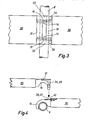
- the embodiment of the scaffolding covering according to the invention shown in FIGS. 3 and 4 likewise consists of a plurality of planks 30 laid one behind the other and possibly also next to one another, which can consist of shaped steel sheet, wooden planks and / or also of other suitable materials.
- the planks 30 have flat tabs 31, 32 protruding on their two end faces, on the underside of which the hook-shaped claws 14, 15 are welded.
- the invention is not restricted to the exemplary embodiments shown.
- other means for the direct connection at both ends of two planks laid on a scaffold can also be used, which ensure a positive connection in the longitudinal direction of the plank as well as in the transverse direction of the plank.
- box sections made of molded sheet steel is particularly useful for the manufacture of the planks, other planks, e.g. Planks, gratings or the like assembled from wooden boards are used.
Abstract
Description
Die Erfindung betrifft einen Gerüstbelag für Baugerüste, insbesondere für Stahlrohrgerüste, bestehend aus schubsteifen Dielen, die an den Stirnseiten hakenförmige Halterungen zur formschlüssigen Auflage-Befestigung an den Querriegeln des Baugerüsts aufweisen und gegen willkürliches Abheben von den Querriegeln gesichert sind.The invention relates to a scaffolding covering for scaffolding, in particular for tubular steel scaffolding, consisting of shear-resistant planks, which have hook-shaped brackets on the end faces for form-fitting support attachment to the crossbars of the scaffolding and are secured against arbitrary lifting off the crossbars.
Gerüstbeläge bilden die Laufstege und Arbeits-Standflächen für die auf dem Gerüst beschäftigten Personen und gehören aus diesem Grunde zu den wichtigsten Elementen eines Baugerüstes. Daneben haben sie jedoch noch die weitere wichtige Funktion einer Längs- und Querversteifung der gesamten Gerüstkonstruktion. Aufgrund dieser besonderen Bedeutung für die Standfestigkeit des Baugerüstes und für die Sicherheit der auf dem Gerüst beschäftigten Personen bestehen in verschiedenen Ländern strenge Bestimmungen für die Eigenschaften der einzelnen Dielen sowie für ihre Verlegung und sichere Befestigung.Scaffolding coverings form the catwalks and work stands for the people working on the scaffolding and are therefore one of the most important elements of scaffolding. In addition, however, they also have the other important function of longitudinal and transverse stiffening of the entire scaffolding structure. Due to this special importance for the stability of the scaffolding and for the safety of the people working on the scaffolding, there are strict regulations in various countries for the properties of the individual planks as well as for their laying and secure fastening.
Bei den sog. Rahmengerüsten, deren Rahmen aus zwei seitlichen Stahlrohrständern und zwei mit diesen verschweißten Querriegeln bestehen, sind Beläge bekannt, deren Dielen an den Stirnseiten formsteife Haken tragen. Die oberen Querriegel jedes Rahmens sind in Form eines nach oben offenen U-Profils ausgebildet, in dessen vertikale Seitenschenkel die Dielen mit den stirnseitigen Haken eingehängt werden. Um ein unbeabsichtigtes oder willkürliches Herausheben der Dielen bzw. ihrer Haken aus den U-Profilen der Querriegel zu vermeiden, sind die unteren Querriegel das nächstoberen Gerüstes als Rohre ausgebildet und in einem solchen Abstand angeordnet, daß sie von oben gegen die Haken drücken und/oder eine Aushebebewegung der Haken nach oben verhindern. Diese Gerüstbeläge sind für sog. Modul-Gerüste, die aus einzelnen Rohrständern und an deren Tragkonsolen montierten rohrförmigen Querriegeln vor Ort zusammengebaut werden, nicht einsetzbar. Darüber hinaus verleihen diese bekannten Gerüstbeläge den Baugerüsten eine häufig unzureichende Steifigkeit in Richtung der Querriegel, d.h. senkrecht zu den Fassadenwänden.In the so-called frame frameworks, the frames of which consist of two lateral tubular steel stands and two crossbars welded to them, coverings are known whose planks carry dimensionally stable hooks on the end faces. The top Crossbars of each frame are designed in the form of an upwardly open U-profile, in the vertical side legs of which the planks are hung with the hooks on the front. In order to avoid unintentional or arbitrary lifting of the planks or their hooks from the U-profiles of the crossbars, the lower crossbars of the next upper scaffold are designed as tubes and are arranged at such a distance that they press against the hooks from above and / or prevent lifting of the hooks upwards. These scaffolding coverings cannot be used for so-called modular scaffolds that are assembled on site from individual tube stands and tubular crossbars mounted on their support brackets. In addition, these known scaffolding coverings often give the scaffolding insufficient rigidity in the direction of the crossbars, ie perpendicular to the facade walls.
Bei einer anderen Ausführung der Gerüstbeläge für Rahmengerüste weisen die Dielen an ihren stirnseitigen Enden mehrere Querbohrungen auf. Die zur Abstützung dieser Dielen vorgesehenen Querriegel der einzelnen Rahmen sind als z.B. Vierkantprofil ausgeführt und tragen an ihren beiden Seiten nach oben vorstehende Zapfen, welche so angeordnet und an den Querriegeln fest angeschweißt sind, daß sie beim Verlegen der Dielen in deren stirnseitige Löcher eingreifen, Dabei ergibt sich zwar ein sicherer Formschluß zwischen den an den Querriegeln sitzenden Stiften und den Bohlen, Voraussetzung ist jedoch die Verwendung von Querriegeln mit seitlich überstehenden Zapfen oder Vierkant-Querschnitt, um eine ausreichende Auflagefläche für die Dielen zu gewährleisten. Der Nachteil dieser Riegelausführung besteht darin, daß auf diese Riegel wegen der überstehenden Zapfen, insbesondere in den Modul-Gerüsten, keine handelsüblichen Dielen verlegt werden können. Auch die für Rahmenmgerüste geeigneten Dielen können nicht auf die üblichen rohrförmigen Riegel bei Modul- und sonstigen Rohrgerüsten mit gleichen Achsabständen verlegt werden, da sie zu kurz sind und damit auf diesen Riegeln nicht aufgelegt werden können. Aus diesem Grunde ist eine Anwendung dieser Gerüstbeläge bei modernen Modul-Gerüsten nicht möglich.In another version of the scaffolding coverings for frame scaffolds, the planks have a plurality of cross holes at their front ends. The crossbars provided for supporting these planks of the individual frames are designed, for example, as a square profile and have upwardly projecting pegs on both sides, which are arranged and welded to the crossbars so that they engage in the end holes of the planks when laying the planks Although there is a secure positive fit between the pins on the crossbars and the planks, the prerequisite is the use of crossbars with laterally protruding pegs or a square cross-section to ensure a sufficient contact surface for the planks. The disadvantage of this bolt design is that there are none on these bolts because of the protruding pins, particularly in the module frames commercially available planks can be installed. Even the planks suitable for frame scaffolding cannot be installed on the usual tubular transoms with modular and other tubular scaffolding with the same center distances, since they are too short and therefore cannot be placed on these transoms. For this reason, it is not possible to use these scaffolding coverings with modern modular scaffolding.
Modul-Gerüste zeichnen sich bekanntlich dadurch aus, daß sie nicht aus einzelnen in sich formsteifen Rahmen sondern aus einer Vielzahl von Einzelteilen bestehen, die vor Ort dann in individueller und vielgestaltiger Weise zusammengebaut werden können. Die verwendeten Rohrständer besitzen in vorgegebenen vertikalen Abständen formsteife ringförmige Tragkonsolen, an denen die Längsstreben und auch die Querriegel mit Hilfe besonderer Befestigungselemente angeschlossen werden. Der Vorteil derartiger Modul-Gerüste ist ihre universelle Anwendbarkeit und die Vielgestaltigkeit ihrer Anpassung an unterschiedliche Bauwerke. Problematisch kann jedoch unter Umständen die Erzielung der geforderten Steifigkeit der Gerüstkonstruktion sein. Zur horizontalen Aussteifung sind bei diesem Gerüsttyp rohrförmige Längs- und Querriegel erforderlich, deren Enden über geeignete Keilverbindungen od. dgl. an den ringförmigen Tragkonsolen der Stahlrohrständer befestigt werden. Die Rohrprofile der Längs- und Querriegel sind notwendig, um die hohen wirksamen Kräfte ohne Deformationen aufnehmen und übertragen zu können. Zur Befestigung des Gleitbelages auf den Querriegeln sind hakenförmige Klauen an den beiden Stirnseiten der Dielen mit gegenseitiger Versetzung angeschweißt, deren innere Auflagefläche entsprechend den Riegeldurchmessern gerundet ist und die die Querriegel übergreifen. Eine wirksame Gerüstversteifung, insbesondere gegenüber den quer zur vertikalen Außenfläche des Bauwerks wirkenden Kräften, läßt sich nicht erreichen.As is well known, modular scaffolds are characterized by the fact that they do not consist of individual, inherently rigid frames but of a large number of individual parts which can then be assembled on site in an individual and varied manner. The pipe stands used have dimensionally stable, ring-shaped support brackets at predetermined vertical intervals, to which the longitudinal struts and also the crossbars are connected using special fastening elements. The advantage of such modular scaffolding is its universal applicability and the diversity of its adaptation to different structures. Under certain circumstances, however, achieving the required rigidity of the scaffold structure can be problematic. For horizontal bracing, tubular longitudinal and transverse bars are required for this type of scaffold, the ends of which are fastened to the ring-shaped support brackets of the tubular steel stands by means of suitable wedge connections or the like. The tubular profiles of the longitudinal and crossbeams are necessary to absorb and transmit the high effective forces without deformation. To fix the sliding surface on the crossbars, hook-shaped claws are welded to the two end faces of the planks with mutual displacement, the inner contact surface of which is rounded in accordance with the crossbar diameters and which overlap the crossbars. An effective scaffold stiffening, especially against the Forces acting transversely to the vertical outer surface of the building cannot be achieved.
Aufgabe der Erfindung ist es, einen Gerüstbelag zu schaffen, der für Rahmengerüste ebenso wie für Modul-Gerüste ohne Umrüstung geeignet ist und der eine wirksame horizontale Aussteifung der Gerüstkonstruktion bewirkt.The object of the invention is to provide a scaffolding covering which is suitable for frame scaffolding as well as for modular scaffolding without retrofitting and which brings about an effective horizontal stiffening of the scaffolding construction.
Diese Aufgabe wird erfindungsgemäß durch die Merkmale des Patentanspruchs 1 gelöst.This object is achieved by the features of claim 1.
Durch die erfindungsgemäße zusätzliche starre und formschlüssige gegenseitige Verbindung der Stirnseiten der hintereinander verlegten Dielen durch besondere Verbindungsmittel werden die auf bestimmte Dielen bzw. auf entsprechende Gerüstabschnitte einwirkenden horizontalen Schub- und Zugkräfte nicht - wie bisher - nur auf den die jeweiligen Dielen tragenden Querriegel, sondern auch von einer Diele auf die nächstfolgende übertragen. Der allseitig wirkende Formschluß dieser erfindungsgemäßen Dielenverbindung bewirkt somit eine wesentliche Versteifung der Gerüstkonstruktion, und zwar insbesondere gegenüber den in Richtung der Längsachse der Querriegel wirkenden Kräften quer zur Außenwand des Bauwerks. Versuche haben ergeben, daß durch die zusätzliche Verbindung der Dielen-Stirnseiten untereinander diese Quersteifigkeit eines Modul-Gerüstes gegenüber herkömmlichen Gerüsten um ein Vielfaches gesteigert wird.Due to the additional rigid and positive mutual connection of the end faces of the boards laid one behind the other by means of special connecting means, the horizontal thrust and tensile forces acting on certain boards or on corresponding scaffold sections are not - as was previously the case - only on the crossbars carrying the respective boards, but also transferred from one hall to the next. The all-round positive locking of this board connection according to the invention thus brings about a substantial stiffening of the scaffold structure, in particular with respect to the forces acting in the direction of the longitudinal axis of the crossbars transversely to the outer wall of the structure. Tests have shown that the transverse stiffness of a modular scaffold is increased by a multiple compared to conventional scaffolds by the additional connection of the end faces of the planks.
Bei einer besonders zweckmäßigen Ausgestaltung der Erfindung bestehen die zusätzlichen Befestigungselemente aus U-förmigen Krampen, die von oben in entsprechend positionierte Löcher an den Stirnenden zweier benachbarter Dielen eingreifen. Diese U-förmigen Krampen über tragen nicht nur die in Längsrichtung der Dielen wirksamen Schub- und Zugkräfte von einer Diele zur anderen, sondern können auch die quer zur Wand des Bauwerks nach außen wirkenden "Abzugskräfte" aufnehmen und damit die gesamte Gerüstkonstruktion wirksam aussteifen.In a particularly expedient embodiment of the invention, the additional fastening elements consist of U-shaped staples which engage from above in correspondingly positioned holes at the ends of two adjacent planks. These U-shaped cramps over not only bear the shear and tensile forces effective in the longitudinal direction of the planks from one plank to the other, but can also absorb the "pulling forces" acting outwards transversely to the wall of the building and thus effectively stiffen the entire scaffolding structure.
Zweckmäßig sind mehrere dieser Krampen an der Unterseite von Querstreben angeschweißt. Diese Ausführung hat die besonderen Vorteile, daß sich nicht nur der Versteifungseffekt vergrößert, sondern gleichzeitig auch die Montage and Verlegung der Gerüstbeläge vereinfacht. Ferner können die so ausgebildeten Dielen als Gerüstbeläge für Rahmengerüste ebenso wie für Modul-Gerüste verwendet werden, was sich bezüglich der Lagerhaltung und auch der Montage vorteilhaft auswirkt. Die hohe Versteifungswirkung dieser Gerüstbeläge hat den weiteren praktischen Vorteil, daß die bisher zur Erzielung der erforderlichen Steifigkeit notwendigen Längsriegel häufig entfallen können, was die Kosten des gesamten Gerüstes und dessen Auf- und Abbau erheblich vermindert. Für besonders hoch belastete Modul-Gerüste können natürlich von Fall zu Fall in herkömmlicher Weise zusätzliche Versteifungswirkungen durch Verwendung von Längs- und/oder Diagonalriegeln erzielt werden.Appropriately, several of these staples are welded to the underside of cross struts. This version has the particular advantages that not only the stiffening effect increases, but also the assembly and laying of the scaffolding decking is simplified. Furthermore, the planks designed in this way can be used as scaffolding coverings for frame scaffolding as well as for modular scaffolding, which has an advantageous effect with regard to storage and also assembly. The high stiffening effect of these scaffolding coverings has the further practical advantage that the longitudinal bars previously required to achieve the required rigidity can often be dispensed with, which considerably reduces the costs of the entire scaffolding and its assembly and disassembly. For particularly highly loaded module scaffolds, additional stiffening effects can of course be achieved in the conventional manner by using longitudinal and / or diagonal bars.
Die die nach unten weisenden Krampen tragenden Querstreben sind zweckmäßig als Flacheisen ausgebildet und greifen in entsprechende Einsenkungen an den Stirnrändern der beiden hintereinander verlegten Dielen ein, so daß ihre Oberfläche in etwa mit der Oberfläche der Dielen übereinstimmt.The cross struts bearing the downward-facing cramps are expediently designed as flat irons and engage in corresponding depressions on the end edges of the two planks laid one behind the other, so that their surface corresponds approximately to the surface of the planks.
Gemäß einer anderen zweckmäßigen Ausgestaltung der Erfindung kann jede Diele an ihrer einen Stirnseite mindestens zwei Löcher und an der anderen Stirnseite zwei Zapfen für den Eingriff in die Löcher der nächstfolgenden Diele aufweisen. Zweckmäßig sind die Zapfen an der Unterseite von Laschen befestigt, welche die angrenzenden Randstreifen der benachbarten Diele übergreifen.According to another expedient embodiment of the invention, each plank can have at least one two holes on one end face and two pins on the other end face for engaging in the holes of the next plank. The pins are expediently fastened to the underside of tabs which overlap the adjacent edge strips of the adjacent plank.
Die bisher übliche untere Querverbindung der Rahmen, die vorwiegend aus Rund-, Quadrat- und Recheckrohren besteht und damit eine Stolpergefahr vorgibt, wird durch die Flacheisen oder z.B. Halbrundprofile ersetzt, an deren Unterseite die Verbindungszapfen befestigt sind. Die Stolpergefahr ist durch die damit geänderte untere Querverbindung behoben.The previously common lower cross connection of the frames, which mainly consists of round, square and rectangular tubes and thus pretends to trip, is replaced by the flat bars or e.g. Half-round profiles replaced, on the underside of which the connecting pins are attached. The risk of tripping is eliminated by the modified lower cross connection.
Die einzelnen Dielen des erfindungsgemäßen Gerüstbelages bestehen vorteilhaft aus einem gelochten Stahlblech und haben im Querschnitt die Form eines Kastenprofils mit nach innen eingebogenen unteren Randkanten. Die Löcher für den Eingriff der Krampen bzw. der Stifte sind vorzugsweise in horizontalen Laschen von vehrfach abgewinkelten Profilteilen mit seitlichen Zungen ausgeführt. Diese Profilteile werden von der Stirnseiten her in das Kastenprofil der Dielen auf Maß eingeschoben und fest verschweißt.The individual planks of the scaffolding covering according to the invention advantageously consist of a perforated steel sheet and have the shape of a box profile in cross-section with inwardly bent lower edge edges. The holes for the engagement of the staples or the pins are preferably carried out in horizontal tabs of multi-angled profile parts with lateral tongues. These profile parts are pushed into the box profile of the planks from the front and welded to size.
Im folgenden wird die Erfindung anhand von Ausführungsbeispielen unter Bezugnahme auf die Zeichnung im einzelnen beschrieben. Es zeigen:
- Fig. 1 eine perspektivische Ansicht eines Teils eines Rahmengerüstes mit einem Gerüstbelag gemäß der Erfindung;
- Fig. 2 eine andere Ausführung des erfindungsgemäßen Gleitbelags in Anwendung bei einem Modul-Gerüst in perspektivischer Darstellung;
- Fig. 3 eine weitere Ausführung des erfindungsgemäßen Gleitbelags in Draufsicht;
- Fig. 4 die Ausführung des Gleitbelags nach Fig. 3 in Seitenansicht.
- Figure 1 is a perspective view of part of a frame with a scaffold covering according to the invention.
- 2 shows another embodiment of the sliding covering according to the invention in use in a module frame in a perspective view;
- 3 shows a further embodiment of the sliding covering according to the invention in plan view;
- Fig. 4 shows the execution of the sliding surface of FIG. 3 in side view.
Gemäß Fig. 1 besteht das Rahmengerüst aus einem unteren Rahmen 1 und einem oberen Rahmen 2. Jeder Rahmen besitzt vertikale Stahlrohrständer 3, 4, die an ihrem unteren Ende durch einen Querriegel 5 und an ihrem oberen Ende durch einen rohrförmigen Querriegel 6 starr und unlösbar, z.B. durch Schweißen, miteinander verbunden sind. Die Stahlrohrständer 3, 4 des oberen Gerüstes 2 werden mit ihren nach unten offenen Enden auf vertikale Längszapfen 7, 8 aufgesteckt, die am oberen Ende der beiden Stahlrohrständer 3ʹ , 4ʹ des jeweils unteren Rahmens vorstehend befestigt sind. Die oberen Querriegel 6 jedes Rahmens dienen als Tragelemente für Dielen 10, die bei dem Ausführungsbeispiel nach Fig. 1 jeweils zweifach nebeneinander verlegt sind und den Gerüstbelag bilden. An den beiden Stirnseiten jeder Diele 10 ist ein Profilelement aus z.B. gebogenem Stahlblech angeschweißt, das eine in Längsrichtung über die Stirnkante der eigentlichen Diele vorstehende Lasche 11 besitzt, in welcher zwei durchgehende Querlöcher 12 ausgebildet sind. Die Positionierung ist so vorgenommen, daß sich die Löcher von jeweils zwei hintereinander verlegten Dielen genau gegenüberliegen. An der Unterseite der Laschen 11 sind ferner hakenförmige Klauen 14 angeschweißt, wie sie beispielsweise in Fig. 4 dargestellt sind und auch bei herkömmlichen Modul-Gerüsten Verwendung finden. Diese Klauen übergreifen in der in Fig. 4 darge stellten Weise den jeweiligen Querriegel, wobei die Klauen 14 an einer Stirnseite der Diele 10 gegenüber den Klauen 14 an der anderen Stirnseite um vorgegebene Beträge seitlich gegeneinander versetzt sind, um ein gemeinsames Übergreifen des rohrförmigen Querriegels 6 zu ermöglichen.1, the frame structure consists of a lower frame 1 and an upper frame 2. Each frame has vertical tubular steel stands 3, 4, which are rigid and non-detachable at their lower end by a
Bei der dargestellten Ausführung bestehen die einzelnen Dielen aus Stahlblech, das zu einem Kastenprofil mit einer ggf. aufgerauhten Tragfläche und nach unten abgebogenen Seitenwänden 15 sowie nach innen eingebogenen Randkanten 16 besteht. Die aus mehrfach abgewinkelten Stahlblechzuschnitten gebildeten Profilteile 13, die an ihrer Stirnseite die Laschen 12 tragen, sind in die offenen Stirnenden der Kastenprofile eingeschoben und verschweißt. Zur Tragfläche der kastenförmigen Stahlblech-Dielen 10 bilden die vorstehenden Laschen 11 einen Absatz, dessen Höhe in etwa der Wandstärke des Dielen-Stahlblechs entspricht. Bei Verwendung von anders geformten Dielen aus Stahlblech oder anderen geeigneten Materialien kann die durch die Laschen gegenüber der Tragfläche der Diele gebildete Einsenkung auch auf andere Weise hergestellt werden.In the embodiment shown, the individual planks are made of sheet steel, which consists of a box profile with a possibly roughened wing and
Wie in Fig. 1 dargestellt, ist die untere Querstrebe 5 des oberen Rahmens 2 aus einem Flacheisen ausgeführt und trägt an ihrer Unterseite insgesamt vier U-förmige Krampen 18, die in Längsrichtung des Gerüstbelages ausgerichtet und an der Querstrebe 5 in vorbestimmten Abständen angeschweißt sind. Die Position und die Größe dieser U-Krampen 18 ist so gewählt, daß sie bei einer Absenkbewegung des oberen Rahmens in die Lochpaare 12 jeweils zweier benachbarter Laschen 11 an den beiden zueinander weisenden Stirnseiten von im Abstand zueinander verlegten Dielen 10 eingreifen und auf diese Weise die Dielen zusätzlich zu ihrer Halterung auf den Querstreben 6 mittels der hakenförmigen Klauen 14 formsteif miteinander verbinden.As shown in Fig. 1, the
Die in Fig. 2 dargestellte Ausführung entspricht in ihrem wesentlichen Aufbau der Ausführung nach Fig. 2, wobei gleiche Bezugszeichen für gleiche Bauteile verwendet sind. Statt einer Doppellage wie bei der Ausführung nach Fig. 1 besteht der Gerüstbelag aus jeweils drei nebeneinander verlegten Dielen 10, welche mit den Dielen 10 der Ausführung nach Fig. 1 identisch sind. Diese Dielen 10 werden als Gerüstbelag bei einem sog. Modul-Gerüst verwendet, an dessen vertikalen Stahlrohrständern 23, 24 in vorgegebenen Abständen ringförmige Tragkonsolen 25 angeschweißt sind. Diese Tragkonsolen dienen in üblicher Weise zum festen Anschluß von Quer- und/oder Längsriegeln mit Hilfe von besonderen Befestigungselementen, welche die Kragen der Ringkonsolen umgreifen und ggf. durch Keile oder Schwenkhebel gesichert werden. Die verwendeten Querriegel 26 haben Rohrprofil und dienen als Auflageelemente für die Dielen 10, welche in der in Fig. 4 unten dargestellten Weise von den an den stirnseitigen Laschen 11 der Dielen angeschweißten hakenförmigen Klauen übergriffen werden. Als weiterer Unterschied gegenüber der Ausführung nach Fig. 1 sind die Krampen 18 an der Unterseite einer Querstrebe 27 angeschweißt, die als gesamtes Bauteil in Flachprofil, z.B. als Flacheisen, ausgebildet ist. Nachdem die verschiedenen Dielen 10 in der in Fig. 2 dargestellten Weise auf der Querstrebe positioniert worden sind, wird das Flacheisen 27 so über die Dielenlaschen 11 gelegt, daß die Zapfen der Krampen 18 in die jeweiligen Lochpaare 12 eingreifen. Aufgrund der Einsenkung schließt die Oberfläche der flachen Profilstrebe 17 mit den Oberflächen der Dielen zumindest in etwa ab, so daß der gesamte Gleitbelag eine weitgehend ebene Gehfläche erhält und Stolpergefahren vermieden werden.The embodiment shown in FIG. 2 corresponds in its essential structure to the embodiment according to FIG. 2, the same reference numerals being used for the same components. Instead of a double layer as in the embodiment according to FIG. 1, the scaffolding covering consists of three
Die in den Fig. 3 und 4 dargestellte Ausführung des erfindungsgemäßen Gerüstbelages besteht ebenfalls aus mehreren hintereinander und ggf. auch nebeneinander verlegten Dielen 30, die aus geformtem Stahlblech, aus Holzbohlen und/oder auch aus anderen geeigneten Materialien bestehen können. Die Dielen 30 weisen an ihren beiden Stirnflächen vorstehende flache Laschen 31, 32 auf, an deren Unterseite die hakenförmigen Klauen 14, 15 angeschweißt sind. Wie aus Fig. 3 ersichtlich, befinden sich an den seitlichen Verlängerungen 33 der Laschen 31 Bolzen 34, 35, die neben den hakenförmigen Klauen 14, 15 an der Unterseite angeschweißt sind. Beim Zusammenbau zweier Dielen 30 greift jeweils einer dieser beiden Bolzen 34, 35 in die Querbohrung 36, 37 ein, die in der Lasche 32 ausgebildet ist, wodurch eine direkte Verbindung der Stirnseiten der beiden Dielen 30 zusätzlich zu ihrer Halterung durch die hakenförmigen Klauen 14, 15 auf dem Querriegel zustandekommt.The embodiment of the scaffolding covering according to the invention shown in FIGS. 3 and 4 likewise consists of a plurality of
Die Erfindung ist nicht auf die dargestellten Ausführungsbeispiele beschränkt. So können insbesondere auch andere Mittel zur direkten beidendigen Verbindung zweier auf einem Gerüst verlegter Dielen Verwendung finden, die einen Formschluß in Dielenlängsrichtung ebenso wie in Dielenquerrichtung gewährleisten. Obgleich die Verwendung von Kastenprofilen aus geformtem Stahlblech zur Herstellung der Dielen besonders zweckmäßig ist, können auch andere Dielen, z.B. aus Holzbrettern zusammengebaute Dielen, Roste od. dgl. Verwendung finden.The invention is not restricted to the exemplary embodiments shown. In particular, other means for the direct connection at both ends of two planks laid on a scaffold can also be used, which ensure a positive connection in the longitudinal direction of the plank as well as in the transverse direction of the plank. Although the use of box sections made of molded sheet steel is particularly useful for the manufacture of the planks, other planks, e.g. Planks, gratings or the like assembled from wooden boards are used.
Claims (10)
gekennzeichnet durch
zusätzliche Befestigungselemente (12, 18; 34 bis 37) an den Stirnseiten der Dielen (10; 30), welche zwei hintereinander verlegte Dielen (10 , 30) formsteif und starr miteinander verbinden.1. Scaffolding covering for scaffolding, in particular for tubular steel scaffolding, consisting of shear-resistant planks which have hook-shaped brackets on the end faces for form-fitting attachment to the crossbars of the scaffolding and are secured against arbitrary lifting off,
marked by
Additional fastening elements (12, 18; 34 to 37) on the end faces of the planks (10; 30), which connect two planks (10, 30) laid one behind the other in a rigid and rigid manner.
dadurch gekennzeichnet,
daß als Verbindungselemente Querbohrungen (12) an den beiden Stirnseiten der Dielen (10) vorgesehen sind, in welche die als weitere Verbindungselemente dienenden Zapfen von U-förmigen Krampen (18) von oben eingreifen.2. scaffolding covering according to claim 1,
characterized,
that transverse bores (12) are provided as connecting elements on the two end faces of the planks (10), into which the pins of U-shaped clamps (18) serving as further connecting elements engage from above.
dadurch gekennzeichnet,
daß die Krampen (18) an der Unterseite von Querstreben (5, 27) befestigt sind.3. scaffolding covering according to claim 2,
characterized,
that the cramps (18) are attached to the underside of cross struts (5, 27).
dadurch gekennzeichnet,
daß die Querstreben (5) beidendig mit den unteren Enden zweier Stahlrohrständer (3, 4) fest verbunden sind.4. scaffolding covering according to claim 3,
characterized,
that the cross struts (5) are firmly connected at both ends to the lower ends of two tubular steel stands (3, 4).
dadurch gekennzeichnet,
daß die Querstreben (5, 27) als Flacheisen ausgebildet sind.5. scaffolding covering according to claim 3 or 4,
characterized,
that the cross struts (5, 27) are designed as flat bars.
dadurch gekennzeichnet,
daß die Ränder an den Stirnseiten der Dielen (10) um einen durch die Höhe der flachen Querstrebe (5, 27) vorgegebenen Betrag eingesenkt sind.6. scaffolding covering according to one of claims 1 to 5,
characterized,
that the edges on the end faces of the planks (10) are countersunk by an amount predetermined by the height of the flat cross strut (5, 27).
dadurch gekennzeichnet,
daß an einer Stirnseite jeder Diele (30) mehrere Löcher (34, 35) und an der anderen Stirnseite jeder Diele (30) zwei nach unten weisende Zapfen (34, 35) für den Eingriff in die Löcher (36, 37) der nächstfolgenden unteren Diele (30) vorgesehen sind.7. scaffolding covering according to claim 1,
characterized,
that on one end face of each plank (30) a plurality of holes (34, 35) and on the other end face of each plank (30) two downward-pointing pins (34, 35) for engaging in the holes (36, 37) of the next lower one Floorboard (30) are provided.
dadurch gekennzeichnet,
daß die Löcher (12; 36, 37) bzw. die Zapfen (34, 35) an der Unterseite von Laschen (11; 31, 32) befestigt sind.8. scaffolding covering according to one of claims 1 to 7,
characterized,
that the holes (12; 36, 37) or the pins (34, 35) on the underside of tabs (11; 31, 32) are attached.
dadurch gekennzeichnet,
daß die Dielen (10, 30) aus Stahlblech bestehen und im Querschnitt die Form eines Kastenprofils mit nach innen eingebogenen unteren Randkanten (16) haben.9. scaffolding covering according to one of claims 1 to 7,
characterized,
that the planks (10, 30) consist of sheet steel and in cross section have the shape of a box profile with inwardly bent lower edge edges (16).
dadurch gekennzeichnet,
daß die Laschen (11, 31, 32) an mehrfach abgewinkelten Blechprofilteilen mit seitlichen Zungen ausgeführt sind, welche stirnseitig in das an den Enden offene Kastenprofil der Dielen (10, 30) auf Maß eingesteckt und verschweißt sind.10. scaffolding covering according to claim 9,
characterized,
that the tabs (11, 31, 32) are made on multi-angled sheet metal profile parts with lateral tongues, which are inserted and welded to the front in the box profile of the planks (10, 30) which is open at the ends.
Priority Applications (1)
| Application Number | Priority Date | Filing Date | Title |
|---|---|---|---|
| EP86104001A EP0238680A1 (en) | 1986-03-24 | 1986-03-24 | Platform for scaffolds |
Applications Claiming Priority (1)
| Application Number | Priority Date | Filing Date | Title |
|---|---|---|---|
| EP86104001A EP0238680A1 (en) | 1986-03-24 | 1986-03-24 | Platform for scaffolds |
Publications (1)
| Publication Number | Publication Date |
|---|---|
| EP0238680A1 true EP0238680A1 (en) | 1987-09-30 |
Family
ID=8194996
Family Applications (1)
| Application Number | Title | Priority Date | Filing Date |
|---|---|---|---|
| EP86104001A Withdrawn EP0238680A1 (en) | 1986-03-24 | 1986-03-24 | Platform for scaffolds |
Country Status (1)
| Country | Link |
|---|---|
| EP (1) | EP0238680A1 (en) |
Cited By (5)
| Publication number | Priority date | Publication date | Assignee | Title |
|---|---|---|---|---|
| EP0965706A1 (en) * | 1998-06-19 | 1999-12-22 | Wilhelm Layher Vermögensverwaltungs-GmbH | Vertical frame for a scaffolding |
| WO2006024302A1 (en) * | 2004-09-01 | 2006-03-09 | Pf Management Holding Aps | Scaffold board with hooks having inclining front edges |
| WO2012064204A2 (en) * | 2010-11-10 | 2012-05-18 | Hugh Gordon Mccarroll | A scaffold and method for construction of same |
| US20180119435A1 (en) * | 2016-11-03 | 2018-05-03 | Alum-A-Pole Corporation | Support member for joinable scaffolding planks |
| CN113802769A (en) * | 2021-10-13 | 2021-12-17 | 西安建筑科技大学 | Steel pipe clamping layer concrete lattice column connected by sleeve type batten strip and construction method |
Citations (7)
| Publication number | Priority date | Publication date | Assignee | Title |
|---|---|---|---|---|
| US3306397A (en) * | 1965-05-24 | 1967-02-28 | Elmer L Brumenshenkel | Sectional platform or support for use with scaffolding |
| FR2175494A5 (en) * | 1972-03-08 | 1973-10-19 | Haefla Bruks Ab | |
| EP0017957A1 (en) * | 1979-04-21 | 1980-10-29 | Gerhard Dobersch | Scaffold working platform consisting of separate planks |
| DE7936629U1 (en) * | 1979-12-28 | 1981-06-11 | Dobersch, Gerhard, 5090 Leverkusen | WORKING STAGE ON SCAFFOLDING |
| DE8118239U1 (en) * | 1980-06-26 | 1981-10-22 | F.A.P. Fabbrica Attrezzature Prefabbricate Per L'Edilizia "Praticus" S.p.A., Lodigiana Graffignana, Milano | SCHEDULE FOR A SCAFFOLDING |
| DE3211548A1 (en) * | 1981-03-30 | 1982-11-04 | Floby Durk AB, 52040 Floby | SCAFFOLDING CONNECTOR |
| GB2105397A (en) * | 1981-08-27 | 1983-03-23 | Thomas Ltd Martin | Scaffolding platform support |
-
1986
- 1986-03-24 EP EP86104001A patent/EP0238680A1/en not_active Withdrawn
Patent Citations (7)
| Publication number | Priority date | Publication date | Assignee | Title |
|---|---|---|---|---|
| US3306397A (en) * | 1965-05-24 | 1967-02-28 | Elmer L Brumenshenkel | Sectional platform or support for use with scaffolding |
| FR2175494A5 (en) * | 1972-03-08 | 1973-10-19 | Haefla Bruks Ab | |
| EP0017957A1 (en) * | 1979-04-21 | 1980-10-29 | Gerhard Dobersch | Scaffold working platform consisting of separate planks |
| DE7936629U1 (en) * | 1979-12-28 | 1981-06-11 | Dobersch, Gerhard, 5090 Leverkusen | WORKING STAGE ON SCAFFOLDING |
| DE8118239U1 (en) * | 1980-06-26 | 1981-10-22 | F.A.P. Fabbrica Attrezzature Prefabbricate Per L'Edilizia "Praticus" S.p.A., Lodigiana Graffignana, Milano | SCHEDULE FOR A SCAFFOLDING |
| DE3211548A1 (en) * | 1981-03-30 | 1982-11-04 | Floby Durk AB, 52040 Floby | SCAFFOLDING CONNECTOR |
| GB2105397A (en) * | 1981-08-27 | 1983-03-23 | Thomas Ltd Martin | Scaffolding platform support |
Cited By (7)
| Publication number | Priority date | Publication date | Assignee | Title |
|---|---|---|---|---|
| EP0965706A1 (en) * | 1998-06-19 | 1999-12-22 | Wilhelm Layher Vermögensverwaltungs-GmbH | Vertical frame for a scaffolding |
| WO2006024302A1 (en) * | 2004-09-01 | 2006-03-09 | Pf Management Holding Aps | Scaffold board with hooks having inclining front edges |
| WO2012064204A2 (en) * | 2010-11-10 | 2012-05-18 | Hugh Gordon Mccarroll | A scaffold and method for construction of same |
| WO2012064204A3 (en) * | 2010-11-10 | 2012-07-05 | Hugh Gordon Mccarroll | Modular scaffold and tensioned bracing arrangement and method of construction. |
| US20180119435A1 (en) * | 2016-11-03 | 2018-05-03 | Alum-A-Pole Corporation | Support member for joinable scaffolding planks |
| US10604951B2 (en) * | 2016-11-03 | 2020-03-31 | Alum-A-Pole Corporation | Support member for joinable scaffolding planks |
| CN113802769A (en) * | 2021-10-13 | 2021-12-17 | 西安建筑科技大学 | Steel pipe clamping layer concrete lattice column connected by sleeve type batten strip and construction method |
Similar Documents
| Publication | Publication Date | Title |
|---|---|---|
| EP0918912B2 (en) | Dismountable facade scaffold | |
| EP1899553B1 (en) | Ceiling formwork system | |
| EP1571275A2 (en) | Device for the assembling of a temporary railing of a scaffold | |
| DE10108784A1 (en) | Scaffold with vertical supports and horizontal girders | |
| DE3117409A1 (en) | "CLIMBING FORMWORK" | |
| WO1998041713A1 (en) | Scaffolding with vertical and diagonal poles | |
| EP2798133B1 (en) | Panel for a system ceiling formwork, and a system ceiling formwork | |
| DE102007021159B4 (en) | Rostdeckenschalung for the integration of a column | |
| DE19511847A1 (en) | Support structure arrangement for scaffolding | |
| AT17062U1 (en) | Mobile working scaffold | |
| DE102004004883B4 (en) | Ceiling formwork panel and system ceiling formwork | |
| DE3108020A1 (en) | "PROTECTIVE DEVICE FOR METAL FRAME" | |
| DE3036306C2 (en) | Stripping aid for slab formwork | |
| EP0238680A1 (en) | Platform for scaffolds | |
| EP1370736B2 (en) | System of structural components for podiums/stages and/or stands and/or rostrums | |
| EP3563017A1 (en) | Scaffold platform and method for producing same | |
| DE3245126A1 (en) | Gang-board for facade scaffoldings | |
| EP0736648B1 (en) | Scaffold | |
| EP3354818B1 (en) | Length alignment assembly for construction scaffolding | |
| EP0851074B1 (en) | Scaffolding for platform, staging or floorshuttering | |
| DE3312582A1 (en) | FORMWORK FOR PRODUCING SIDES ON CONCRETE CEILINGS | |
| EP3839172B1 (en) | Railing post for a front railing, front railing for temporarily preventing falls from a new scaffolding level, scaffold for building, repair and/or assembly work and method for constructing a scaffold | |
| WO1998041712A1 (en) | Dismountable scaffolding with base plates arranged on cross struts | |
| DE3040707C2 (en) | ||
| DE802280C (en) | Scaffolding |
Legal Events
| Date | Code | Title | Description |
|---|---|---|---|
| PUAI | Public reference made under article 153(3) epc to a published international application that has entered the european phase |
Free format text: ORIGINAL CODE: 0009012 |
|
| AK | Designated contracting states |
Kind code of ref document: A1 Designated state(s): AT BE CH DE FR GB IT LI LU NL SE |
|
| RBV | Designated contracting states (corrected) |
Designated state(s): BE DE FR GB IT NL |
|
| STAA | Information on the status of an ep patent application or granted ep patent |
Free format text: STATUS: THE APPLICATION HAS BEEN WITHDRAWN |
|
| 18W | Application withdrawn |
Withdrawal date: 19880330 |
|
| RIN1 | Information on inventor provided before grant (corrected) |
Inventor name: DOBERSCH, GERHARD |